Production of Solar Fuels using CO
2
DOCTORAL THESIS
Universita` degli Studi di Messina (HOME) and
École supérieure de chimie physique électronique de Lyon, Université Claude Bernard Lyon 1 (HOST)
SINCHEM - Sustainable and Industrial Chemistry Erasmus Mundus - Joint Doctoral Research program
Dottorato di XXIX ciclo in
Ingegneria e Chimica dei Materiali e delle Costruzioni and
Ecole Doctorale N° 206
(Ecole Doctorale de Chimie de Lyon : Chimie, Procédés, Environnement) Supervisor (HOME): Prof.ssa Siglinda PERATHONER
Co-Supervisor: Dr. Claudio AMPELLI
Supervisor (HOST): Prof.ssa Elsje Alessandra QUADRELLI Co-Supervisor: Dr. Chloe THIEULEUX
Thesis by
Bhanu Chandra MAREPALLY
April, 2017
ii
Doctoral Defense Committee :
University of Messina
FORNASIERO, Paolo Prof. Universita degli Studi di Trieste Referee
FONSECA, Isabel Prof. Universida de Nova de Lisboa, Referee
LECLAIRE, Julien Prof. Université de Lyon 1 Jury (Internal)
CENTI, Gabriele Prof. Universita degli Studi di Messina Jury (Internal)
DI RENZO, Francesco Prof. CNRS, ICG Montpellier Jury (External)
GARCIA GOMEZ, Hermenegildo Prof. Universidad Politecnica de Valencia Jury (External)
PERATHONER, Siglinda Prof. Universita degli Studi di Messina Supervisor
QUADRELLI, Elsje Alessandra Prof. Université de Lyon 1 Supervisor
University of Lyon
DI RENZO, Francesco Prof. CNRS, ICG Montpellier Referee
GARCIA GOMEZ, Hermenegildo Prof. Universidad Politecnica de Valencia Referee
CENTI, Gabriele Prof. Universita degli Studi di Messina Jury
LECLAIRE, Julien Prof. Université de Lyon 1 Jury
PERATHONER, Siglinda Prof. Universita degli Studi di Messina Supervisor
iii
Dedicated
To
My Beloved
P
arents, my
W
ife
&
iv
EPIGRAPH
Every event in the history of time
can be defined by the
v
ACKNOWLEDGEMENT
First and foremost, I express my deepest gratitude and love to the God Almighty for his grace to give me this wonderful opportunity to work in this fascinating field of artificial photosynthesis.
Now, I would like to express my love to my dear father – M .Rajender Rao, my dear mother – Lakshmi Devi, my Late grandfather – E. Raj Gopal Rao, my brother – Sharath Chandra, my sister-in-law – Sravani Deekshit, my loving wife – Sindhoora and my relatives for their continuous support and encouragement to walk the path of my heart. I thank all my ancestors for all their secret blessings.
I am forever grateful and I express my heartfelt thanks to Late Dr. Jewan Prakash Raina my Guru, ex-Senior Professor & Director, Centre for Nano Technology, VIT, India for his timely guidance & motivation all along my Masters and his advices to overcome the obstacles & keep moving forward to solve real world problems not just limited to the field of Nano Technology.
Any PhD. degree is not possible without a great guiding mind. I am very thankful to have Prof. Siglinda Perathoner, University of Messina, Italy as my principal advisor. I will never forget all the support you gave me with the many official works in Messina and the warmly welcome on my first day of my life in a foreign country. I still think, if it is coincidence or destiny that we both are born on the same day.
In life, there are times, when we need to make critical decisions, some show you the path and you will understand their meaningful words only as time passes! I thank you Prof. Elsje Alessandra Quadrelli, for your better judgment and guidance even before you became my second principal advisor from CPE, Universite Claude Bernard Lyon, France.
Although, I got to speak to Prof. Gabrielle Centi only a handful times, I am very inspired by his work culture and passion towards research, thank you for being the anchor to all our research and experimentations.
Most of the times, professors are busy with a lot of works, I am very lucky to have Dr. Claudio Ampelli, as a Co-supervisor and more a mentor, guiding me on each step of my PhD research.
vi
My research work at UCBL Lyon was for a short period, but I was fortunate to get guidance from Dr. Chloe Thieuleux in a few discussions. I would also like to thank Dr. Jerome Canivet for the precise expertized teachings on MOF synthesis techniques in a very short time.
All these acknowledgements would not have been possible without SINCHEM. I sincerely thank SINCHEM program, the committee, and all its professors for their constant support and encouragement. A special thanks to Prof. Stefania Albonetti, SINCHEM coordinator, for making this program not just a give and take, but a close family with strong scientific as well as cultural roots spread across the world.
I thank the University of Messina, Italy, École supérieure de chimie physique électronique de Lyon (CPE), Claude Bernard University (UCBL), Lyon 1, France and Institut de recherches sur la catalyse et l'environnement de Lyon, France (IRCE Lyon) for the necessary support and facilities.
I express my sincere thanks to Dr. Gargi Raina, Dr. Nirmala Grace, Dr. Bala Praveen Chakkravarthy, Dr. V. Velmurugan, Dr. Harish Kittur, Dr. P. Penchalaiah, Dr. George Jacob and Dr. K. Sivasankaran VIT University for their guidance and support during my Masters.
The seeds towards research are not sowed and reaped in a day - I would like to thank Dr. Chandrasekhar Mukku, Dr. M. B. Srinivas, Dr. R. Govindarajulu, Dr. G. Ram Murthy, Mr. Madhusudhan Rao, Dr. Vinayak Rao, Dr. K. Srinivasa Chary, Dr. U. Trivikram, Mrs. T. Naga Sree, Dr. V. Vishwanath Rao, Dr. Jaisval and Dr. Laxmi Narayana Prusty for their teachings and creation of strong foundation and thoughts in the field of science and technology.
Every research lab is defined by its group of researchers, each one of them contribute in some way along your journey of PhD. A simple thanks would never suffice for the many things you have taught me – it may be basic chemistry or laboratory pre-cautions or analytical tools and techniques or experimental procedures or fun talks about nothing and everything. You have been there for me right from my first step till the end, Thank you – Giorgia, Chiara, Salvatore, Paolo, Francesco, Maria Grazia, Roberto Pizzi, Gianfranco, Paola, Rosalba, Katia, Serena, Maria, Leone, Roberto Di Chio, Robert, Andres, Chalachew, Chen, Reine, Florian Wisser, Audrey, Iuliia, Tibo, David, Matthieu, Stephane, Walid, Bishoy, Ewelina, Aabid, Fred, Saranya, Gouthami, Felix, Ram and Santosh Rauri.
vii
Engineering and tools play a major role in research, I thank Laurent Veyre, for his support with the electron-microscopy techniques and Daniele Cosio, for his support with mechanical designing of the cells.
A special thanks to my first friend abroad Atif, our saviors ‘saint’ Anna Maria, Mrs. Francesca Pollicino, Angela Garozzo, Macro Fabienne, Maria Angelina Beaucourt, Francois Bayard, Catherine Dallagnol and Lina Lagana.
A special thanks to our very own 1st SINCHEM family - Giuliana, Atif, Olena, Yu Zhang, Maria, Emilia, Tahrizi and Asja.
I thank my very special friends Tapish, Vishnu, Late Raju, Harish, Arya, Harsha, Mahesh, Naidu, Raghu, Sunil, Sumanth, Vamsi, Sundar, Rahim, Satheesh, Soundara Rajan, Chaithanya, Saurabh, Pooja, Kamran, Khaoula, Ramzi, Kiran Kumar, Jagadeesh, Mohan and Sreedhar.
I thank all my gamer friends who made my life, a notch more electrifying.
And last but not the least, I thank all my fellow conscious group of atoms, directly or indirectly responsible for the existence of this event in the history of time.
viii
ix
Abstract (English)
In view of the recent alarming rate of depletion of fossil fuel reserves and the drastic rise in the CO2 levels in the atmosphere leading to global warming and severe climate changes, tapping
into all kinds of renewable energy sources has been among the top priorities in the research fields across the globe. One of the many such pathways is CO2 reduction to fuels using
renewable energies, more commonly referred as artificial photosynthetic cells or artificial leaves or photo-electro-catalytic (PEC) cells.
The key objective of the present PhD work was to conduct in-depth studies on two different electro-catalytic CO2 reduction systems: electrolyte-less cell (gas phase) and electrolytic cell
(liquid phase). In particular, a novel lab scale liquid phase cell, on the similar lines of the previously realized gas phase cell at the University of Messina, was developed and used to convert electro-catalytically CO2 to more value-added products. The work was carried out at
the Laboratory CASPE/INSTM of the University of Messina (Department of Electronic Engineering, Industrial Chemistry and Engineering). During the second year, a six-month period was spent at the École supérieure de chimie, physique, électronique de Lyon (CPE Lyon), where organometallic routes were explored for the synthesis of novel composite materials to be used as electrocatalysts in the CO2 reduction process.
Experimental tests were carried out on various types of catalysts in both the gas and liquid phase cells to understand the different selectivity, productivity and the reaction products obtained. Liquid phase, in fact, has been the most studied process in literature, but some issues mainly related to CO2 solubility and types of products formed (i.e. mainly formic acid), have
never be allowed to pass the lab scale stage. The general aim of this PhD was to prepare novel metal doped nanocarbon substrates, which are very different with respect to the conventional metal bulk layers used as electrocatalysts in CO2 reduction, and test them both in gas phase (to
take advantage of these conditions, i.e easy recovery and improved quality of the products) and in liquid phase (to have a better comparison with conditions typically adopted in literature).
For the studies on the electro-catalytic reduction of CO2 in gas phase cell, a series of electrodes
(based on Cu, Fe, Pt and Cu/Fe metal nanoparticles – NPs - deposited on carbon nanotubes – CNTs - or carbon black and then placed at the interface between a Nafion membrane and a gas-diffusion-layer) were prepared. The results, evidencing the various types of products formed and their different productivities, are very promising. Under electrolyte-less conditions, the
x
formation of ≥C1 products (such as ethanol, acetone and isopropanol) were observed, the highest being for Fe and closely followed by Pt, evidencing that also non-noble metals can be used as efficient catalysts under these conditions. To enhance the productivities of the CO2
reduction, a different set of electrodes were also prepared based on substituted Zeolitic Imidazolate (SIM-1) type MOF coatings during a stay at CPE Lyon and Institut de recherches sur la catalyse et l'environnement de Lyon (IRCELYON). Particularly, the catalysts tested were MOF-based Fe-CNTs, Pt-CNTs and Cu/Fe-CNTs. There was a significant change in the reaction products and in the selectivity towards the end-products. Particularly, especially for the MOF modified Pt based catalyst, there was an increase in the C-products and also a better selectivity towards higher C-products.
Moving to the studies on the electro-catalytic reduction of CO2 in liquid phase cell, a similar
set of electrodes were prepared. Initially, electrodes based on metal NPs of Cu, Fe, Pt, Ru and Co deposited on CNTs or carbon black were studied for their CO2 reduction capability. The
relative order of productivity in CO2 electro-catalytic reduction in these series of electrodes
was found to be different between the gas and liquid phase cells indicating the different reaction pathways. For liquid phase conditions, in terms of net C-products, catalytic electrodes based on Pt topped the class, closely followed by Ru and Cu, while Fe got the lowest position. The probable underlying reaction mechanism was also provided.
In order to improve further the performances of the CO2 reduction in liquid phase conditions,
a metal NPs size dependant study on the electro-catalytic reduction of CO2 to fuels was carried
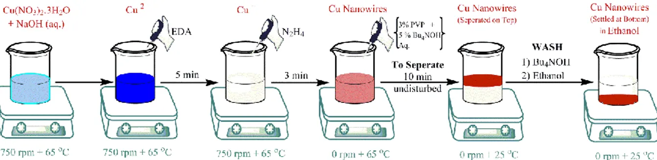
out. This study was performed using electrodes based on metal NPs of Ru, Fe, Pt and Cu loaded on CNTs and then transferred on a gas diffusion layers (GDL). Varied sized metal NPs have been synthesized using different techniques: (i) impregnation route to achieve NPs in the size range of 10-50 nm; (ii) organometallic approach to synthesize uniform and ultrafine NPs in the size range of 5 nm (i.e., Fe NPs were synthesized through a novel synthesis route to attain 1-3 nm NPs); (iii) Nanowire (NW) top-down approach to obtain ultrafine copper metal NPs in the size range of 2-3.8 nm. Particularly, the novelty of nanowire approach is the ability to obtain very small metal NPs starting from the synthesis of Cu NWs and then transferring the Cu onto the carbon surface, taking advantage of the different inter-forces of between Cu NWs and the functional groups present on the partially oxidized CNT surface. Furthermore, unlike the case of organo-metallic approach, this approach allows a preparation under air avoiding the use of potentially demanding inert atmospheric conditions.
xi
The enhancements in the fuel productivity were found to be 5-30 times higher for the smaller metal NPs obtained via organo-metallic route or nanowire route as compared to the larger metal NPs obtained via impregnation route. The results signify that the smaller sized metal NPs loading on the CNTs have a prevailing role in the catalytic performance and the selectivity towards different products. Moreover, the percentage of metal NPs loading was significantly reduced from 10 to 1-2 wt. % producing higher or equivalent fuels for small NPs as compared to the larger NPs. The reusability of the working electrodes and long reaction times (until 24 hours) were also probed.
A different set of electrodes based on nano-foams on metal foils, were also investigated to achieve further improvements in the electro-reduction of CO2 to fuels. These nano-foams or
dendrites were prepared by electrochemical deposition technique. Optimization studies on the deposition of these foams were performed initially to fix the set of preparation conditions. Moreover, voltage optimization study was performed using cyclic voltammetry and full CO2
reduction tests to find the optimum voltage for the process. The nano-foam electrodes tested include Cu and Fe foams on Cu foil, Fe foil, Al foil, Inconel foil and Al grid/mesh. The enhancements in the fuel productivity for various foams were in the range of 2-10 times greater as compared to the highest net fuel productivity achieved using metal NPs doped carbon catalytic electrodes, from all the previous studies.
Various characterizations and analysis tools were used to analyse the catalysts qualitatively and quantitatively, which include Transmission Electron Microscopy (TEM), Scanning Electron Microscopy (SEM), Atomic Absorption Spectroscopy (AAS), X-ray diffraction (XRD), X-ray Photo-electron spectroscopy (XPS), and Brunauer-Emmett-Teller (BET). To determine the fuel productivities, Ion Chromatography (IC), Gas Chromatography-Mass Spectrometer (GC-MS), Gas Chromatography (GC) were used.
Keywords: CO2 reduction; electrochemical cells; electo-catalysis; electrolyte-less conditions;
gas phase; liquid phase; nano-foams (NFs); metal nano-particles (NPs); Cu nanowires (NWs); organo-metallic route; carbon nanotubes (CNTs); Metal-organic frameworks (MOFs); gas diffusion layers (GDL).
xii
Abstract (Italian)
Alla luce del recente allarmante tasso di esaurimento delle riserve di combustibili fossili e al contemporaneo drastico aumento dei livelli di CO2 nell'atmosfera, principale gas serra
responsabile del riscaldamento globale e di cambiamenti climatici molto gravi, una delle priorità assolute nella ricerca a livello mondiale è quella di sfruttare il più possibile le fonti di energia rinnovabile. Una possibilità molto interessante è quella di realizzare un processo di riduzione della CO2 a combustibili liquidi che sfrutti energie rinnovabili, quale quella solare,
mediante dispositivi più comunemente noti come celle fotosintetiche artificiali o foglie artificiali o celle foto-elettro-catalitiche (PEC).
L'obiettivo principale di questo lavoro, è stato pertanto quello di condurre uno studio approfondito su due diversi sistemi elettrocatalitici di riduzione della CO2 a prodotti liquidi con
un più alto valore aggiunto, uno operante in fase gassosa (cioè in assenza di elettrolita al catodo) e uno operante in fase liquida. In particolare, è stata progettata e utilizzata nel processo di conversione della CO2, un’innovativa cella in fase liquida operante su scala di laboratorio, sulla
falsariga della cella in fase gas precedentemente sviluppata all’Università di Messina. Il lavoro è stato svolto principalmente presso il laboratorio CASPE/INSTM dell’Università degli Studi di Messina (Dipartimento di Ingegneria Elettronica, Chimica e Ingegneria Industriale). Un periodo di sei mesi è stato svolto invece, nel corso del secondo anno di dottorato, presso l’École supérieure de chimie, physique, électronique de Lyon (CPE Lyon). In tale periodo sono stati sintetizzati, mediante innovative tecniche di sintesi organometallica, materiali compositi da utilizzare come elettrocatalizzatori nel processo di riduzione della CO2.
Sono state effettuate molteplici prove sperimentali utilizzando svariate tipologie di catalizzatori, sia in fase gas che in fase liquida, al fine di indagare la differente selettività, produttività e varietà di prodotti ottenuti. Il processo in fase liquida è infatti quello maggiormente studiato in letteratura, ma esistono alcune problematiche che devono essere superate per consentire un successivo semplice scale up. quali ad esempio, la scarsa solubilità della CO2 e la tipologia di prodotti ottenuti (principalmente acido formico).
Lo scopo principale di questo lavoro è stato quello di preparare nuovi materiali a base di carboni dopati con metalli, catalizzatori questi molto diversi da quelli comunemente utilizzati nel processo di riduzione della CO2 (generalmente metalli in bulk), e di testarli sia in fase gas (per
xiii
qualità dei prodotti stessi) sia in fase liquida (per avere un miglior confronto con i dati ampiamente presenti in letteratura).
Per gli studi sulla riduzione elettrocatalitica della CO2 nella cella operante in fase gassosa, sono
stati preparati una serie di elettrodi (basati su nano particelle –NP- di Cu, Fe, Pt e Cu/Fe depositate su nanotubi di carbonio o carbon black e successivamente poste all'interfaccia tra una membrana di Nafion e uno strato a diffusione di gas –GDL-). I risultati ottenuti sono stati molto promettenti, sia in termini di tipologia di prodotti formati che di produttività. In fase gas (senza elettrolita) è stata osservata la formazione di prodotti ≥C1 quali etanolo, acetone e isopropanolo, in particolare utilizzando il Fe (seguito dal Pt), evidenziando che anche metalli non nobili possono essere usati in maniera efficiente in questo processo.
Per migliorare la produttività nella reazione di riduzione della CO2, sono stati preparati elettrodi
differenti, basati su coating con sostituti zeolitici imidazolici (SIM-1) tipo MOF. In particolare, i catalizzatori testati sono stati MOF modificati con Fe-CNT, Pt-CNT, e CuFe-CNT. E’ stato osservato un cambiamento significativo in termini di produttività e anche di selettività verso i prodotti finali. Nel dettaglio, in particolare per il catalizzatore a base di MOF modificato con Pt, è stato osservato un aumento nei prodotti carboniosi e anche una selettività più alta verso prodotti con un più elevato numero di atomi di C.
Per quanto riguarda lo studio del processo di riduzione elettrocatalitica della CO2 utilizzando
la cella operante in fase liquida, sono state preparate tipologie di elettrodi simili ai precedenti. Inizialmente infatti, sono stati studiati elettrodi a base di nanoparticelle metalliche (Cu, Fe, Pt, Ru, Co) depositate su nanotubi di carbonio o carbon black. L'ordine relativo della produttività nella riduzione elettrocatalitica della CO2 in questa serie di elettrodi, è però risultato essere
diverso rispetto alla fase gassosa, indicando quindi un differente percorso di reazione. In termini di produttività totale, gli elettrodi a base di Pt hanno consentito di ottenere le migliori performance, seguiti da Ru e Cu, mentre il Fe ha dato risultati peggiori. Sulla base dei risultati sperimentali ottenuti, è stato inoltre ipotizzato un possibile meccanismo di reazione.
Successivamente, per cercare di migliorare ulteriormente le prestazioni nel processo di riduzione della CO2 in fase liquida, è stato effettuato uno studio approfondito, volto ad indagare
la dipendenza di tale processo dalle dimensioni delle nanoparticelle metalliche. A tale scopo sono stati utilizzati elettrodi a base di nanoparticelle metalliche (Ru, Fe, Pt e Cu) su nanotubi di carbonio (CNT) depositati su GDL. Sono state sintetizzate nanoparticelle metalliche di
xiv
diverse dimensioni utilizzando molteplici tecniche di sintesi: (i) impregnazione che ha consentito di ottenere NP di dimensioni comprese tra 10-50 nm; (ii) sintesi organometallica che ha consentito di ottenere NP uniformi e ultrafine con dimensioni comprese tra 1-5 nm. (ad esempio sono state sintetizzate NP di Fe di 1-3 P nm) (iii) sintesi mediante nanowires che ha consentito di ottenere NP di rame ultrafine con dimensioni comprese tra 2-3,8 nm.
In particolare, la novità dell’approccio mediante nanowires sta nella possibilità di ottenere particelle di dimensioni molto piccole sintetizzando inizialmente i Cu NWs, mettendoli poi a contatto con il supporto carbonioso e facilitandone il suo trasferimento, ciò grazie alle forze intermolecolari di attrazione dei gruppi funzionali presenti sui CNT parzialmente ossidati. Inoltre, a differenza della sintesi organometallica, tale approccio permette di condurre le reazioni in aria e non in atmosfera inerte.
I valori di produttività ottenuti sono stati 5-30 volte più alti utilizzando nanoparticelle metalliche più piccole (ottenute via nanowires o mediante sintesi organometallica) rispetto alle nanoparticelle metalliche più grandi (ottenute per impregnazione). I risultati sperimentali indicano pertanto che le NP di dimensioni più piccole hanno un ruolo fondamentale nelle performance catalitiche. Inoltre, il carico di NP metalliche è stato significativamente ridotto dal 10% al 1-2% in peso consentendo di ottenere, per le NP più piccole, una produttività equivalente o addirittura superiore rispetto alle nanoparticelle più grandi. In seguito, è stato effettuato anche uno studio sul possibile riutilizzo degli elettrodi di lavoro e sulla disattivazione per tempi di reazione più lunghi.
E’ stata infine preparata una diversa tipologia di elettrodi a base di nano-foams su lastrine metalliche, al fine di ottenere un ulteriore miglioramento nel processo di riduzione elettrocatalitica della CO2. Le nano-foams o dendriti, sono state preparate mediante la tecnica
di deposizione elettrochimica ed è stato effettuato uno studio preliminare di ottimizzazione, al fine di determinare le condizioni di sintesi più adatte.
In aggiunta, è stato eseguito uno studio specifico per ottimizzare il valore di Voltaggio da utilizzare nelle prove catalitiche, mediante sia test di voltammetria ciclica che test completi di riduzione della CO2. Sono stati testati nano-foams a base di Cu e Fe depositati su fogli di Cu
Fe, Al, di Inconel e su una griglia di Al. L’aumento nella produttività usando queste tipologie di elettrodi, è stata nell’ordine di 2-10 volte rispetto alla massima produttività ottenuta utilizzando NP metalliche su materiali carboniosi.
xv
Svariate tecniche analitiche sono state poi utilizzate per caratterizzare in modo approfondito i materiali preparati tra cui, microscopia elettronica a trasmissione (TEM), microscopia elettronica a scansione (SEM), spettroscopia ad assorbimento atomico (AAS), diffrazione a raggi X (XRD), spettroscopia fotoelettronica a raggi X (XPS), determinazione dell’area superficiale mediante metodo Brunauer-Emmett-Teller (BET). La determinazione dei prodotti di reazione è stata effettuata invece mediante cromatografia ionica (IC), gas cromatografia con rivelatore a spettrometria di massa (GC-MS), gas cromatografia (GC) con rivelatore a termo conducibilità (TCD).
Parole chiave: Riduzione della CO2; celle elettrochimiche; elettro-catalisi; assenza di
elettrolita; fase gassosa; fase liquida; nano-schiume (NFs); nano-particelle (NPs); nano-fili (NWs); sintesi organo-metallica; nanotubi di carbonio (CNT); strutture metallo-organiche (MOF); elettrodi a diffusione dei gas (GDE).
xvi
Abstract (French)
Compte tenu du récent taux alarmant d'épuisement des réserves de combustibles fossiles et de l'augmentation drastique des niveaux de CO2 dans l'atmosphère qui a conduit au réchauffement
de la planète et à des changements climatiques sévères, l'exploitation de toutes sortes d'énergies renouvelables a été la Parmi les principales priorités de la recherche Champs à travers le monde. L'une des nombreuses voies de ce genre est la réduction du CO2 aux combustibles utilisant des
énergies renouvelables, plus communément appelées cellules photosynthétiques artificielles ou feuilles artificielles ou cellules photoélectro-catalytiques (PEC).
L'objectif principal de ce travail était de réaliser des études approfondies sur les différents systèmes de réduction électro-catalytique du CO2, à savoir les cellules sans
électrolyte (phase gazeuse) et les cellules électrolytiques (phase liquide). Dans ce processus, nous avons conçu une nouvelle cellule en phase liquide à échelle de laboratoire sur les lignes similaires de la cellule de phase gazeuse de modèle précédemment modélisée. Des essais expérimentaux sur la réduction du CO2 ont été réalisés sur différents types de catalyseurs dans
les deux cellules afin de comprendre la sélectivité, la productivité et les produits de réaction obtenus. L'obtention de résultats de test dans les deux cellules nous a permis d'effectuer une comparaison décente avec les résultats de réduction électro-catalytique de CO2 existants dans
la littérature.
Des essais expérimentaux ont été réalisés sur différents types de catalyseurs à la fois dans les cellules en phase gazeuse et en phase liquide pour comprendre la sélectivité, la productivité et les produits de réaction obtenus. La phase liquide, en fait, a été le processus le plus étudié dans la littérature, mais certaines questions liées principalement à la solubilité du CO2 et aux types de produits formés (c'est-à-dire principalement l'acide formique) n'ont jamais été autorisées à franchir le stade de l'échelle du laboratoire. L'objectif général de ce doctorat était de préparer de nouveaux substrats de nanocarbone dopés par des métaux, qui sont très différents par rapport aux couches en vrac métalliques conventionnelles utilisées comme électrocatalyseurs dans la réduction de CO2, et de les tester en phase gazeuse (pour profiter de ces conditions, Une récupération facile et une qualité améliorée des produits) et en phase liquide (pour une meilleure comparaison avec les conditions typiquement adoptées dans la littérature).
xvii
Pour les études sur la réduction électro-catalytique du CO2 en phase gazeuse, une série
d'électrodes (à base de nanoparticules de Cu, Fe, Pt et CuFe déposées sur des nanotubes de carbone ou de noir de carbone puis placées à l'interface entre une membrane Nafion et Une électrode à couche de diffusion de gaz). Les résultats démontrent le type divers de produits formés et leurs productivités. Dans des conditions sans électrolyte, la formation de produits ≥C1 tels que l'éthanol, l'acétone et l'isopropanol a été observée la plus élevée étant pour Fe et suivie de près par Pt. Pour améliorer les productivités de la réduction du CO2, un ensemble
différent d'électrodes a été préparé sur la base de revêtements MOF de type imidazolate de type zéolitique substitué (SIM-1) lors d'un séjour au CPE Lyon et à l'Institut de recherches sur la catalyse et l'environnement de Lyon (IRCELYON). Les catalyseurs testés étaient Fe-CNT, Pt-CNT et CuFe-Pt-CNT basés sur MOF. Il y a eu un changement significatif dans les produits de réaction et aussi, la sélectivité vis-à-vis des produits finaux. Pour le catalyseur à base de Pt modifié, MOF, il y avait une augmentation des produits C et également une sélectivité différente tandis que pour le catalyseur à base de Fe, il y avait une légère diminution des produits C.
En se reportant aux études sur la réduction électro-catalytique du CO2 dans une cellule
en phase liquide, un ensemble similaire d'électrodes a été préparé afin d'obtenir une bonne comparaison des résultats dans les expériences en phase gazeuse. Initialement, des électrodes à base de nanoparticules métalliques (Cu, Fe, Pt, Ru, Co) déposées sur des nanotubes de carbone ou du noir de carbone ont été étudiées pour leur capacité de réduction du CO2. L'ordre
relatif de productivité dans la réduction électrocatalytique de CO2 dans ces séries d'électrodes
a été trouvé différent entre les cellules en phase gazeuse et en phase liquide indiquant les différentes voies de réaction. Pour les conditions de phase liquide, en termes de produits C nets, les électrodes catalytiques à base de Pt sont en tête de la catégorie, suivies de près par Ru et Cu, tandis que Fe a obtenu la position la plus basse. Le mécanisme réactionnel sous-jacent probable a également été fourni.
Afin d'améliorer encore les performances de la réduction du CO2 dans les conditions
de phase liquide, une étude de la nanoparticules métalliques (NPs) dépendant de la taille de la réduction électro-catalytique du CO2 aux combustibles a été réalisée. Ceci a été réalisé à l'aide
d'électrodes à base de nanoparticules métalliques (Ru, Fe, Pt et Cu) chargées sur les nanotubes de carbone (CNT) transférés sur les couches de diffusion gazeuse (GDL). On a synthétisé des nanoparticules de métal de différentes tailles en utilisant différentes techniques de synthèse: (i)
xviii
l'itinéraire d'imprégnation pour obtenir des NP dans la plage de tailles de 10 à 50 nm; (Ii) Approche organométallique pour synthétiser des NPs uniformes et ultrafines dans la plage de tailles de 1-5 nm. Fe ont été synthétisés par une nouvelle voie de synthèse et des conditions pour atteindre des NP de 1 à 3 nm. (Iii) Approche de haut en bas de Nanowire pour obtenir des NP métalliques de cuivre ultrafin dans la plage de taille de 2-3,8 nm. En particulier, la nouveauté de l'aide de nanofils est la capacité à obtenir des particules de très petite taille d'abord la synthèse du Cu NFs, puis de les mettre en contact avec le support carboné et de faciliter son transfert, cela grâce à des forces d'attraction intermoléculaires des groupes fonctionnels présent sur le CNT partiellement oxydée. En outre, contrairement à la synthèse organométallique, cette approche permet d'effectuer les réactions dans l'air et non pas dans une atmosphère inerte.
Les améliorations de la productivité du combustible ont été trouvées être au moins 5 à 30 fois plus élevées pour les NP métalliques de plus petite taille obtenus par voie organo-métallique ou par nanofil, par rapport aux NP organo-métalliques plus grands obtenus par voie d'imprégnation. Les résultats indiquent que les NP métalliques de plus petite taille chargés sur les CNT jouent un rôle prédominant dans la performance catalytique et la sélectivité vis-à-vis de différents produits. En outre, le pourcentage de charge de NP métalliques a été réduit de façon significative de 10% à 1-2% en poids, produisant des carburants plus élevés ou équivalents pour de petites NP en comparaison avec les NP plus grandes. De plus, comme on a observé clairement la productivité en H2 qui a augmenté de nombreux facteurs pour les NP plus petits sur les plus grandes NP. La réutilisabilité des électrodes de travail et les longs temps de réaction ont également été sondés.
Un ensemble différent d'électrodes à base de nano-mousses sur des feuilles métalliques a également été étudié afin d'obtenir des améliorations beaucoup plus importantes de l'électro-réduction de CO2 aux carburants. Ces nano-mousses ou dendrites ont été préparées par une
technique de dépôt électrochimique. Des études d'optimisation sur le dépôt de ces mousses ont été effectuées initialement pour fixer l'ensemble des conditions de préparation. De plus, une étude d'optimisation de la tension a été réalisée en utilisant la voltamétrie cyclique et des tests de réduction de CO2 complets pour fixer une tension optimale pour les réactions. Les électrodes
nano-mousses testées incluent (mousses Cu, Fe sur feuille Cu, feuille Fe, feuille Al, feuille Inconel et grille Al). Les améliorations de la productivité du combustible pour diverses mousses se situaient dans la plage de 2 à 10 fois par rapport à la productivité nette de combustible la plus élevée obtenue en utilisant des électrodes catalytiques en carbone dopé par des NP métalliques.
xix
Différentes caractérisations et outils d'analyse ont été utilisés pour analyser les catalyseurs qualitativement et quantitativement qui incluent la microscopie électronique à transmission (TEM), la microscopie électronique à balayage (SEM), la spectroscopie d'absorption atomique (AAS), la diffraction des rayons X (XRD) La spectroscopie électronique (XPS) et Brunauer-Emmett-Teller (BET) et pour déterminer les productivités des combustibles, chromatographie ionique (IC), chromatographie gazeuse-spectromètre de masse (GC-MS), chromatographie gazeuse.
Mots-clés: Réduction du CO2; des cellules électrochimiques; l'électro-catalyse; absence
d'électrolyte; phase gazeuse; phase liquide; mousses (NFs); particules (NPs); nano-fils (NWs); synthèse organo-métallique; nanotubes de carbone (CNT); structures métallo-organiques (MOF); une électrode de diffusion de gaz (GDE).
xx TABLE OF CONTENTS Dedication………....iii Epigraph...………....iv Acknowledgements………...v Abstract………...viii Table of Contents………...xx
List of Figures………...xxvi
List of Tables………...xxx
CHAPTER PAGE NO 1. General Introduction………...1
1.1 Energy………...1
1.1.1. Global energy perspective……….1
1.1.2. Energy Sources………..1
1.1.3. Global climate change and CO2………1
1.2 Solar Fuels – A key to the global challenge……….5
1.2.1. Photo-catalysis (HER reaction).………6
1.2.2. Electro-catalysis (CO2 reduction)……….8
1.2.2.1. General terms reported in EC CO2 reduction………..9
1.2.3. Thermodynamics and Reaction pathways………...10
1.2.4. Catalysts………..12
1.3 Global research outlook on CO2 reduction……….13
1.4 Thesis (main aim, scope and chapter goals)………...15
xxi
2. CO2 electro-catalytic reduction in electrolyte-less conditions (Gas phase)…………...23
2.1 Introduction……….23
2.1.1. State of the art……….23
2.1.1.1. Preparation of the electro-catalytic material……….23
2.1.1.2. Assembling of the electrodes………25
2.1.1.3. Gas phase cell model and the testing of the electrodes……….25
2.1.1.4. Importance of nano-carbon based substrates………26
2.1.1.5. Fuel productivity and selectivity………...27
2.1.2. Scope of the chapter………28
2.2 Experimental………...28
2.2.1. SIM 1 - MOF synthesis………...28
2.2.2. Working electrode configuration (final template)………...29
2.3 Results and Discussions………...30
2.3.1. Characterization.……….30
2.3.1.1. SEM Morphological Measurements……….31
2.3.2. Electro-catalytic CO2 reduction in Gas phase……….31
2.3.2.1. Voltage profile………..31
2.3.2.2. Fuel Productivity………...32
2.4 Conclusions……….33
2.5 References………...34
xxii
3. Design and performance of a novel cell for CO2 electro-reduction (Liquid phase)……38
3.1 Introduction……….38
3.1.1. State of the art………..38
3.1.2. Scope of the chapter……….39
3.2 Experimental………...40
3.2.1. Preparation of the Electrodes………...40
3.2.2. Basic conditions of the cell………..43
3.3 Results and Discussions………..43
3.3.1. Design and engineering of the liquid phase electro-catalytic Cell………43
3.3.1.1. Modelling and working principles……….43
3.3.1.2. Design Challenges……….46
3.3.2. Characterization………...47
3.3.2.1. Structural Analysis………47
3.3.2.2. TEM Morphological Measurements………..48
3.3.2.3. Surface Analysis………....51
3.3.2.4. Quantitative and physical characterizations………...52
3.3.2.5. Current Profile………...53 3.3.3. Electro-catalytic CO2 reduction………...54 3.3.3.1. Fuel Productivity………...54 3.3.4. Mechanism………...57 3.4 Conclusions……….60 3.5 References………...62 ANNEX3 ……….66
xxiii
4. Size controlled nanoparticles for liquid phase CO2 electro-reduction………70
4.1 Introduction……….70
4.1.1. State of the art (Organo-metallic)………70
4.1.2. State of the art (Nanowire)………...71
4.1.3. Scope of the chapter……….72
4.2 Experimental………...72
4.2.1. Synthesis of metal nanoparticles via organo-metallic route………72
4.2.1.1. Pt nanoparticle synthesis………...72
4.2.1.2. Ru nanoparticle synthesis………..73
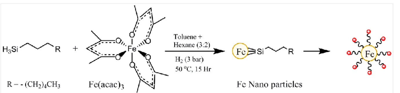
4.2.1.3. Fe nanoparticle synthesis………...74
4.2.2. Synthesis of metal nanoparticles via nanowire route………...74
4.2.3. Preparation of the working electrodes………..76
4.3 Results and Discussions………..77
4.3.1. Organo-metallic route………..77
4.3.1.1. Synthesis and Characterization….………77
4.3.1.1.1. Structural Analysis………...77
4.3.1.1.2. TEM Morphological Measurements………78
4.3.1.1.3. Surface Analysis………...81
4.3.1.1.4. Quantitative and physical characterizations……….82
4.3.1.1.5. Current profile………..83
4.3.1.2. Electro-catalytic CO2 reduction……….84
4.3.1.2.1. Fuel Productivity………..84
4.3.2. Nanowire route (Cu NWs to get Cu NPs)………86
4.3.2.1. Synthesis and Characterization…….………86
4.3.2.1.1. Structural Analysis………...86
xxiv
4.3.2.1.3. Surface Analysis………...89
4.3.2.1.4. Quantitative and physical characterizations………..90
4.3.2.1.5. Current profile………..91 4.3.2.2. Electro-catalytic CO2 reduction……….91 4.3.2.2.1. Fuel Productivity………..91 4.4 Conclusions……….95 4.5 References………...96 ANNEX4……….99
5. Nano foams for liquid phase CO2 electro-reduction………...102
5.1 Introduction………...102
5.1.1. State of the art……….102
5.1.2. Electro-chemical deposition ………..103
5.1.3. Scope of the chapter………...103
5.2 Experimental……….104
5.2.1. Synthesis of metal nano-foams via electro-chemical deposition………...104
5.2.1.1. Cu nano-foam synthesis………...104
5.2.1.2. Fe nano-foam synthesis………...105
5.2.1.3. Metal foils………106
5.3 Results and Discussions………106
5.3.1. Characterization……….106
5.3.1.1. SEM Morphological Measurements………106
5.3.1.2. Surface Analysis………..110
5.3.1.3. Structural Analysis………..110
5.3.1.4. Energy Dispersive X-ray spectroscopy (EDX)………....111
xxv 5.3.1.6. Electro-catalytic CO2 reduction………...112 5.3.1.6.1. Current profile………112 5.3.1.6.2. Voltage Optimization……….113 5.3.1.6.3. Fuel Productivity………113 5.4 Conclusions………...116 5.5 References……….117 ANNEX5………...119
6. General conclusions and perspectives……….123
xxvi
List of Figures
Fig. 1.1 Global carbon emissions from fossil fuels……….3
Fig. 1.2 Global CO2 concentrations over the years……….3
Fig. 1.3 Global CO2 concentrations predictions for the next hundred years………..4
Fig. 1.4 Schematic representation of photo-chemical water splitting……….7
Fig. 1.5 Schematic representation of photo-electro-chemical water splitting……….8
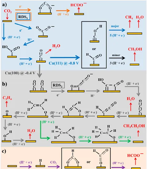
Fig. 1.6 Reaction pathways of CO2 reduction to oxalate, CO, formate on inert electrodes……11
Fig. 1.7 Reaction pathways of CO2 reduction to different products on transition metal and
molecular catalytic electrodes………...11
Fig. 1.8 A graphical view on various categories of electrocatalysts of CO2 reduction……….13
Fig. 2.1 (a) Scheme of the apparatus for electrolyte-less cell tests of CO2 reduction with the
electro-catalyst in contact with a gaseous flux of CO2. (b) Photo of the cell; in the inset view
of the electrode and GDL………..26
Fig. 2.2 Scheme showing MOF synthesis and transfer onto GDL……….29
Fig. 2.3 Scheme showing the configuration of the final electrode template………..29
Fig. 2.4 SEM image of the GDL with MOF cross-sectional view. ………..30
Fig. 2.5 SEM images showing the deposition of the MOFs crystals on the fibres of GDL……31
Fig. 2.6 SEM image showing the thickness of the MOF layer and the GDL……….31
Fig. 2.7 Voltage profiles for MOF modified Pt, Fe – CNTs gas phase reaction………32
Fig. 2.8 H2 and CO productivity in (µmol/min) vs Time (min) ……….32
Fig. 3.1 A Schematic showing treating CNTs to obtain oxygen functionalities………41
Fig. 3.2 A Schematic showing transfer of metal NPs onto the CNTs from NPs/NWs in solvent
and coating metal NP doped CNT based INK on GDL to make the working electrode……….42
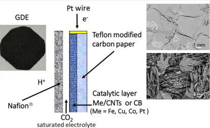
Fig. 3.3 Schematic illustration of the GDE-type electrodes utilized for the CO2 electrochemical
xxvii
right are scanning electron microscopy images of the side at contact with the membrane and of
the side at contact with gas phase (CO2) or the electrolyte in which CO2 is bubbled…………44
Fig. 3.4 Graphical representation of the experimental setup for liquid phase cell for CO2
reduction to fuels………..45
Fig. 3.5 XRD patterns (Impregnation route, 10 wt. % of metal) for (a) bare CNTs, (b) Fe-CNT,
(c) Cu-CNT, (d) Ru-CNT, (e) Pt-CNT……….…47
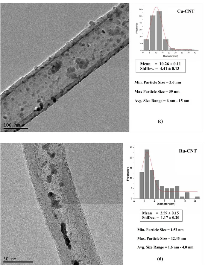
Fig. 3.6 TEM image showing (a) Pt NPs on CNT, (b) Fe NPs on CNT, (c) Cu NPs on CNT,
(d) Ru NPs on CNT, (e) Co NPs on CNT via Impregnation Route………...49, 50, 51
Fig. 3.7 XPS data for bare CNTox - (a) illustration of the C1s and respective deconvolution
spectra, (b) XPS data illustration of the O1s and respective deconvolution spectra………….51
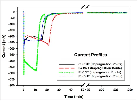
Fig. 3.8 N2 adsorption/desorption isotherms for bare CNTox and Cu-CNTox………53 Fig. 3.9 Current profiles for Cu, Fe, Pt, and Ru loaded CNTs via Impregnation Route……….53
Fig. 3.10 Schematic of the reaction mechanism of CO2 reduction to formic acid………..58
Fig. 3.11 N2 adsorption/desorption isotherms for CNTox, Co, Pt, Fe, Cu, Ru NPs on CNTox…67 Fig. 3.12 Standard three-electrode cell configuration………...68
Fig. 4.1 Schematic showing organo-metallic synthesis of Pt NPs from Pt(dba)2………..73 Fig. 4.2 Schematic showing organo-metallic synthesis of Ru NPs from Ru(cod)(cot)………..73
Fig. 4.3 Schematic showing organo-metallic synthesis of Fe NPs from Fe(acac)3………74 Fig. 4.4 A Schematic with the process steps involved in the Cu Nanowires synthesis………..75
Fig. 4.5 A Schematic showing formation of Cu NPs from Cu NWs on the CNTs……….75
Fig. 4.6 Working electrode preparation by depositing metal NPs + CNT based INK on GDL..76
Fig. 4.7 XRD (OM route) for (a) bare CNTs, (b) Fe-CNT, (c) Ru-CNT, (d) Pt-CNT…………78
Fig. 4.8 TEM image showing Fe NPs colloidal solution via OM route (1 – 3.2 nm)………….79
Fig. 4.9 TEM image showing Pt, Fe, and Ru NPs on CNT via Organo metallic route (0.9 nm -
xxviii
Fig. 4.10 (a, c, e) XPS wide scan survey spectra for Pt, Fe, Ru on CNT catalyst (OM Route) ;
(b, d, f) High-resolution spectrum of the Pt 4f, Fe 2p, Ru 3p doublets and their respective
de-convolution spectra.. ………81
Fig. 4.11 N2 adsorption/desorption isotherms for Ru NPs-CNTox (a) OM, (b) ImR routes...83
Fig. 4.12 Current profiles for OM route (a) Fe CNTox, (b) Pt CNTox, (c) Ru CNTox…………..83 Fig. 4.13 XRD patterns (a) bare CNTs, (b) Cu-CNT (ImR route), (c) Cu-CNT (NW route)….87
Fig. 4.14 TEM image showing (a) Cu NPs on CNT for ImR route (5 nm - 16 nm), (b) Cu
nanowires before deposition onto CNTs………...88
Fig. 4.15 TEM image showing Cu NPs on CNT via NW route (2 nm - 3.8 nm) and STEM
image showing the uniform dispersion of the Cu NPs on the CNT. ………..88
Fig. 4.16 (a) XPS wide scan survey spectra for Cu/CNT catalyst, (b) XPS data illustration of
the C1s and respective deconvolution spectra, (c) High-resolution spectrum of the Cu 2p
doublet and respective de-convolution spectra, (d) XPS data illustration of the O1s and
respective de-convolution spectra. ………...89
Fig. 4.17 N2 adsorption/desorption isotherms for Cu NPs-CNTox (a) NW, (b) ImR route……90
Fig. 4.18 Current profiles for Cu CNTox (a) NW route, (b) 10%, ImR, (c) 1%, ImR route……91
Fig. 4.19 Time dependence vs productivity of formic acid, acetic acid and H2 for Cu NPs on
CNTox (a) 1%, ImR route, (b) 1%, NW route. ………...93
Fig. 4.20 N2 adsorption/desorption isotherms for Pt, Fe, NPs on CNTox (OM & ImR routes).100
Fig. 5.1 Schematic showing Electro-deposition of Cu on metal/semi-conductor………102
Fig. 5.2 Schematic of the Electro-deposition of metal to nano-foam electrodes………..103
Fig. 5.3 SEM image (top view) of the Cu NF on Cu foil with deposition time (a) 1 min, (b) 4
min. ………105
Fig. 5.4 SEM images (top view) of the Cu NF on Cu metal foil with deposition t = 2 min…..106
Fig. 5.5 SEM images of Cu NF on Cu (2 min) - dendrite structures. ………...106
xxix
Fig. 5.7 SEM images of Cu NF on Fe foil (2 min) (a) top view, (b) dendrite close-up………107
Fig. 5.8 SEM images of Cu NF on Al grid (2 min) (a) top view, (b) cross-section view…….108
Fig. 5.9 SEM image of Fe NF on Al foil (deposition time = 2 min). ………...108
Fig. 5.10 (a) XPS wide scan survey spectra for Cu nano-foam on Cu (b) High-resolution
spectrum of the Cu 2p doublets. ………109
Fig. 5.11 XRD pattern of the Cu nano-foam with base substrate as Cu foil……….110
Fig. 5.12 EDX spectra of the Cu nano-foam with base substrate as Cu foil……….110
Fig. 5.13 Current profiles for (a) Cu NF on Cu, (b) Cu Foil, (c) Cu NF on Inconel, (d) Cu NF
on (Al grid + Cu foil). ……….111
Fig. 5.14 Time dependence vs productivity of formic acid, acetic acid, CO and H2 for (a) Cu
NF on Inconel, (b) Cu NF on Al grid + Cu NF on Cu foil. ………..114
Fig. 5.15 EDX spectra for (a) Cu NF on Fe foil; (b) Cu NF on Al grid; (c) Fe NF on Al grid,
xxx
List of Tables
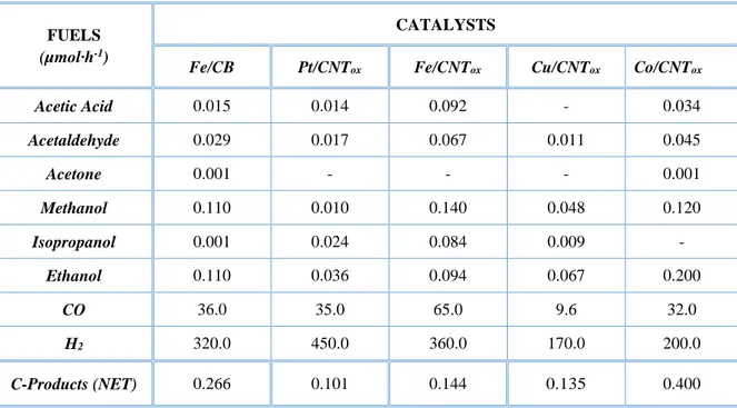
Table 1.1 CO2 reduction potentials for various CO2 reduction reactions products…………...12 Table 1.2 The performance report for various electro-catalysts in CO2 reduction………14 Table 2.1 Properties of commercial GDL and CNTs………24 Table 2.2 Productivity for the CO2 EC reduction in gas phase cell (Units: µmoles per hr)…..27 Table 2.3 Productivity for the CO2 EC reduction in gas phase cell (Units: µmoles per hr)…..33 Table 3.1 A review of the various conditions and the results of CO2 electro-reduction……...39 Table 3.2 Properties of commercial GDL and CNTs………40 Table 3.3 Detailed size distributions of Pt, Fe, Cu, Ru and Co NPs via Impregnation routes…48 Table 3.4 AAS and BET characteristics of Pt, Fe, Cu, and Ru NPs via Impregnation routes…52 Table 3.5 Productivity values for the CO2 EC reduction in liquid phase cell………54 Table 3.6 Productivity values for the CO2 EC reduction in gas phase cell………55 Table 3.7 Comparison of types of products obtained in liquid and gas phase operations in CO2
electro-catalytic reduction………56 Table 4.1 Detailed size distributions of Pt, Fe and Ru NPs via organo-metallic route………79 Table 4.2 Textural characteristics of the electro-catalysts by BET method. ………82 Table 4.3 Productivity for the CO2 EC reduction in liquid phase cell (Units: µmoles/hr)……84 Table 4.4 Approximate calculated no. of surface atoms and the fraction of surface atoms…...86 Table 4.5 Detailed size distributions of Cu-CNT via nanowire (NW) and ImR routes………88 Table 4.6 Textural characteristics of the electro-catalysts by BET method………..91 Table 4.7 Products obtained in the CO2 electro-chemical reduction in liquid phase cell……..92 Table 4.8 TOF values (μmol.s-1.cm-2) on Cu CNT (NW and ImR routes) based electrodes, in comparison with TOF values reported by Kuhl et al. [38] (*) for Cu foil electrode…………...94 Table 5.1 A review of the results of CO2 EC reduction using metals and foams catalysts…...101 Table 5.2 Productivity for the CO2 electro-chemical reduction in liquid phase cell for Cu foil
electrodes for different voltages (Units: µmoles per hr)………..………112 Table 5.3 Productivity for the CO2 electro-chemical reduction in liquid phase cell for
1 | P a g e
1. General Introduction
1.1. Energy
1.1.1. Global energy perspective
World Energy consumption is increasing at an enormous rate, which reached to an average power consumption of 12.3 terawatts (TW) in 2013 (equivalently 1.1*1014 kWh or units) as
compared to ~ 6 TW in 1980 [1]. This extensive rise in the energy consumption depends on various factors: population rise, standards of living, industrial growth, advanced technologies, etc. For instance, the world population has risen from 4.4 billion (1980) to 7.4 billion (current, 2016) [2]and is expected to reach 11.2 billion by 2100 [3], in-turn resetting the expected global energy need to ~ 43 TW [4]. Currently, the global energy dependency in non-renewables or fossil fuels is about 78.1 %, nuclear energy of about 2.7 % and the rest 19.2 % is renewable energy.
1.1.2. Energy Sources
The global energy sources can be broadly classified into: (i) renewable and (ii) non-renewable.
Renewable energy can be defined as the source of energy that can be replenished in an acceptable amount of time. This includes solar energy, hydro-power, wind energy, biofuels, biomass, tidal & wave energy and geo-thermal. In 2016, the individual contributions account for 8.9 % biomass (traditional), 4.2 % heat energy (geo-thermal, modern biomass, solar heat), 3.9 % hydro-electricity and 2.2 % electricity (wind, solar, geo-thermal, biomass) [4-6].
Non-renewable energy can be defined as the source of energy that cannot be replenished at a sufficient rate (a meaningful human-time frame) for sustainable usage. This includes earth minerals and ores, fossil fuels (coal, oil, natural gas, shale gas, etc) and also groundwater in specific aquifers. In 2016, the individual contributions account for 30 % coal, 33 % oil, 24 % natural gas and 2.7 % nuclear energy [4, 6].
1.1.3. Global climate change and CO2
Large and critical changes in climate have happened very quickly in the last years, effecting the global environmental cycle. The climate change can be due to variations in nature such as
2 | P a g e
biotic processes, solar radiation, plate tectonics and volcanic eruptions. However, in recent times this has been effected by unaddressed and unchecked human activities, which have caused the serious phenomenon called global warming. This term refers to the rise in average surface temperatures on Earth (the global temperature increased by 0.8 °C in this century [7]), thus effecting entire planet climatic conditions, agriculture, aquatic life, plant life and human beings alike.
Global warming is mainly due to the human use of fossil fuels and other human activities, which release continuously into the atmosphere enormous amounts of greenhouse gases. The main greenhouse gas is CO2 (81 %), other gases responsible for global warming are
methane (11 %), nitrous oxide (6 %) and fluorinated gases (3 %) [8].
The gases trap heat within the atmosphere, causing various effects on ecosystems, including polar ice-cap melting (increasing the sea level, contributing to greater storm damage), warming ocean temperatures (causing stronger and more frequent storms), severe weather events (leading to floods and other damage), droughts and more severe wildfires. The climate change is thus a complex process depending on various factors as discussed above and each of these factors (natural causes) adjusting itself to the unaccounted add-on factor (greenhouse gases), thus changing the climate for good and making it permanently damaged.
CO2 gas emissions is one of the major role-playing factor in the global warming. CO2 plays a
vital role in the plant life and algae (through photosynthesis), which have evolved from millions of years to form an efficient and renewable process for reducing CO2. The sudden rise in the
CO2 levels in addition to rising temperatures does not give the slightest chance for evolution to
react (as it is a slow process). The CO2 emissions by various systems in the world are as
follows: 91 % from burning fossil fuels and cement production, of which only about 50 % is recycled via absorption by land and ocean and photosynthetic process [9, 10]. The rest remains
accumulated in the atmosphere. As the world energy demand keeps rising, the CO2 emission
and accumulation increase. Fig. 1.1, shows the global carbon emissions data.
As discussed above, the CO2 concentration in the atmosphere continuously increased
for the past two centuries and reached a current concentration of 401.6 ppm (Oct. 2016), i.e. it increased by more than 33 % in the past two centuries. Fig. 1.2, shows the graphical representation of the changes in the CO2 concentrations over the time [11]. These huge level of
3 | P a g e
in global temperature in turn leading to sea level rising [13] and irreversible damage to ecological cycles. This has to be addressed before it crosses a threshold level, a point later cannot be corrected or reverted to reset the environmental conditions to a safe, life supporting level. The prediction of CO2 concentration shown in Fig. 1.3¸ shows the drastic levels of CO2, which
in-turn can lead to a temperature rise of 1 to 5.5 °C, thereby leading to a sea level rise of 20 to 90 cm [14]. The Fig. 1.3, (A1, A2, B1, B2) encompass four combinations of demographic change, social and economic development, and broad technological developments [14]. Two
sub-scenarios of the A1 family (A1FI, A1T) explicitly explore alternative energy technology developments, holding the other driving forces constant, each with an illustrative scenario and IS92a is the scenario predicted in 1992 [14].
Fig. 1.1 Global carbon emissions from fossil fuels [9].
4 | P a g e
Fig. 1.3 Global CO2 concentrations predictions for the next hundred years [14].
Various strategies for decreasing CO2 emissions or accumulation via re-looping CO2
into a renewable fuel production cycle or via capturing and burying large amounts of CO2, are
already in action. Burying CO2 is a currently viable plan but the long term consequences are
still unknown. Alternatively, the excess CO2 (cheap and inexhaustible source of carbon) can
be used as a starting material to synthesize or produce various chemicals or fuels by reduction methodologies, similar to the natural photosynthetic systems. This is sometimes referred to artificial leaves or photosynthesis. However, like all endothermic processes, this process of CO2 reduction to fuels, also needs some amount of energy to drive and sustain the reaction.
Moving closer to the well-established process in the nature, we can embed solar energy as a renewable source for supplying the necessary energy needed for the reduction. Solar energy is one of the most abundant energy source on this planet. The total solar energy hitting the earth in one hour is more than the net global annual energy consumption [15]. Due to the intermittency of insolation and the disparity of intensity over the globe surface, solar energy needs to be stored to become a major primary energy source. Converting solar energy into carbon based fuels through atmospheric CO2 reduction, appears as an appealing solution for the future of
energy demands. Conversion of CO2 using renewable energy sources can be achieved through
various catalytic processes (homogenous, heterogeneous, bio, photo, electro, and photo-electro) [16-38]. In general terms, it is possible to develop a multistep approach, in which
electrical energy is generated using renewable energy sources, and then, H2 is generated in
5 | P a g e
homogeneous or heterogeneous, to convert CO2 to different possible products, such as C1
(formic acid, methane, methanol) or >C1 chemicals (alcohols, dimethyl ether, light olefins, hydrocarbons, etc.). When cheap electrical energy sources are available, converting CO2 by
this approach may be already competitive, as demonstrated from the initiative of Carbon Recycling International (CR) in Iceland (clean Renewable Methanol process) [22]. Other
companies such as Mitsui Chemicals with their ‘‘Green House Gases-to-Chemical Resources’’ technology are active in this field [22]. Also, the conversion of CO
2 to methanol in order to
import renewable energy from remote unused resources, is already economically attractive [39]
and interesting perspectives exist also on producing light olefins from CO2[40].
In a longer-term perspective, it is necessary to reduce the number of steps. A first possibility is to develop inverse fuel cells, where CO2 is directly fed on a special designed
cathodic electrode, able to convert directly CO2 using protons supplied by water oxidation (on
the anodic zone) and electrons supplied externally from a RE source. This is the second type of routes that uses electrochemical or electro-catalytic processes.
In a much longer-time perspective, it is necessary to undertake a fully integrated artificial leaf-type solar cell, where there is the presence of a anode able to photo-electrolyze water using sunlight (photo-electro-catalytic - PEC - solar cell) [41–44]. This is the
third class of routes. Photochemical processes are included in this class, because they realize on a nano-scale, the separation between the processes of generation of protons/electrons from water using light, and those of reduction of CO2 using protons/electrons. PEC solar cells
follows the same idea on a macro-scale, but the physical seggregation of the two processes in different sections, allows lowering self-quenching effects and separating the products at the anode (O2) from those formed at the cathode (products of CO2 EC reduction), with resultant
safer operations. Realizing an efficient and effective electrode for the electro-catalytic conversion of CO2 is a common aspect to both inverse fuel cells and the PEC solar cells.
1.2. Solar Fuels – A key to the global challenge
Artificial photosynthetic systems have deeply been studied from a few decades to harvest solar energy and convert CO2 into important fuels, using systems designed on similar lines based on
the well-established photosynthetic process in nature. The process designed in the late 90s by Moore et al. [45, 46] can be considered as the beginning towards the mimicking of the natural
6 | P a g e
artificial vesicle using sunlight, quite similar in lines of natural photosynthesis. The pH gradient achieved is subsequently used as a power source for the ATPase immobilized in the membrane of the vesicle. This artificial system is simple and has the ability to convert solar energy into ATP far better than the natural photosynthetic system. However, there was an underlying problem, which needed to couple this system to another system that could make use of the generated ATP. This problem could not be addressed, and thereby not able to produce useful products from the energy conversion step. Several groups have focused their attention on the second step of photosynthesis, storing a flow of electrons into chemical bonds [47, 48]. However,
the complexity and high cost-to-fuel of these designs limit the practicality of using them as a base section in artificial leaf-type systems. Though very close mimicking of the primary coordination sphere of the natural active sites have been achieved, they did not show any noteworthy activity towards CO2 reduction. This leads to think of taking a slightly different
approach towards creating artificial leaves, rather than trying to completely mimic the natural system (only the base idea needs to be considered).
1.2.1. Photo-catalysis (HER reaction)
The first reported overall photocatalytic water splitting by a titanium dioxide (TiO2) electrode
was performed by Fujishima and Honda [49]. After this pioneering work, various research
studies on water splitting have been undertaken especially via heterogeneous catalysis using semiconductor materials due their non-overlapping valence bands and conduction bands (with a band gap < insulators and > conductors). When sufficient photochemical energy is provided, excited electrons move into the conduction band, leaving behind electron holes in the valence band and an excess of electrons in the conduction band. These are termed as electron-hole pairs, which play vital roles in the redox reactions of water splitting. Reduction of protons to H2 is
achieved via these electrons, and O2- are oxidized by the holes. In order to start the redox reaction, it is required that the valence band’s highest state should be more positive than water oxidation value (EO2/H2O, 1.23 V vs. Normal hydrogen electrode; NHE), while the conduction bands lowest state should be more negative than the hydrogen evolution potential (EH2/H2O, 0 V vs. NHE) [50].
H2O + 2 h+ 2 H++ ½ O2 Eooxidation = - 1.23 V
2 H+ + 2 e - H
2 Eoreduction = - 0.00 V
7 | P a g e
Thus, the minimum band gap necessary for a viable water-splitting photo-catalyst is 1.23 eV. Accordingly, TiO2, ZrO2, KTaO3, SrTiO3, and BiVO4 fall in this category and are good
candidates for photo-catalytic water-splitting [51–53]. However, this condition is not absolute, as the band gaps of some typical semiconductors such as SiC, ZnO and CdS fit well into the water-splitting redox potential but are not active for water-water-splitting due to photo-corrosion. Photo-corrosion occurs if the anion from the catalyst itself is oxidized by photo-generated holes instead of H2O. Another main challenge with the catalysts is that most semiconductors bandgap
lies under the ultraviolet (UV) band, which accounts for only ~ 4% of the total solar energy (i.e. 40 W/m2 out of the entire 1000 W/m2) [54–56]. To improve the solar energy efficiency, band gap engineering needs to be done to push the photo-catalyst’s ability to work under visible light (i.e. the semiconductor band gap < 3 eV), since visible light contributes to nearly 50 % of the incoming solar energy. Semiconductor catalysts coupled with carbon materials or precious metal nano-particles have shown to have better visible light response [51, 57]. Moreover, metal sulfides, metal nitrides, and some metal-free catalysts proved to be promising candidates for photo-catalytic water splitting by visible light [52, 53, 58 and 59].
The photo-catalytic reactions can be classified into two types: -
Photo-chemical process this type of water-splitting consists of three components: a catalyst, a visible light absorber, and sacrificial electron donor. Although the fundamental principles of photo-chemical and photo-electro-chemical systems are identical, the only difference lies in their setup. As shown in Fig. 1.4, the water-splitting reaction occurs at the semiconductor-electrolyte junction where a necessary potential is generated. The semiconductor should be stable (corrosion free) in the electrolyte. Depending on the band gap position of the semiconductor as discussed above, they can be active in production of H2 or O2 or overall
water-splitting [60].
8 | P a g e
Photo-electro-chemical process: This type, commonly referred as PEC water-splitting, consists of a semiconductor photo-catalyst. When a solar-irradiation greater than its band gap is shined on it, the energy absorbed results in charge separation at the valence and conduction bands. Thereby, generating holes in valence band, which trigger the oxidation of H2O at the
surface of conduction band, and the photo-excited electrons in the conduction band, aid in the reduction of the H+ to H2. In the PEC reactions, semiconductors can be used as photo-cathode
or photo-anode and it is necessary the contact with the electrolyte containing a redox couple
[62]. A schematic of the PEC water-splitting system is provided in Fig. 1.5.
Fig. 1.5 Schematic representation of photo-electro-chemical water splitting [61].
1.2.2. Electro-catalysis (CO2 reduction)
The photo-electro-catalytic route is a complex system that depends on a high number of factors (photo-catalyst, membrane, electrolyte, electro-catalyst, conductivity, leaks, irradiation conditions, voltage/current bias, diffusion, electrode contact and adherence, etc.). Too many parameters need to be considered in order to clearly understand the effects of varying electro-catalysts. In order to simplify this, a direct current/voltage bias was used instead of light-irradiation to simulate the photo-anodic half-cell. This is termed as electro-catalytic (EC) CO2
reduction to fuels.
EC reduction of CO2 involves a multi-step reaction mechanism with complex reaction
pathways and can be classified into two types based on the nature of the catalyst: homogeneous and heterogeneous catalysis. In homogeneous CO2 catalytic reduction systems, the electrode
plays the role as an electron transfer media (similar to photosensitizer in photo-catalytic reduction) to the actual molecular catalyst in the electrolytic solution. In the heterogeneous CO2 catalytic reduction, the reaction occurs at the electrode-electrolyte interface, with the
![Fig. 1.8 A graphical view on various categories of electrocatalysts of CO 2 reduction [75]](https://thumb-eu.123doks.com/thumbv2/123dokorg/4583681.38819/44.892.112.789.379.716/fig-graphical-view-various-categories-electrocatalysts-reduction.webp)
![Table 1.2 The performance report for various electro-catalysts in CO 2 reduction [105]](https://thumb-eu.123doks.com/thumbv2/123dokorg/4583681.38819/45.892.61.838.145.943/table-performance-report-various-electro-catalysts-reduction.webp)