DOTTORATO DI RICERCA IN SCIENZE DELL’INGEGNERIA
CICLO XXII
COORDINATORE Prof. TRILLO STEFANO
A F.E. UPPER BOUND LIMIT ANALYSIS MODEL FOR MASONRY CURVED AND 3D STRUCTURES, WITH AND WITHOUT
FRP-REINFORCEMENT
Settore Scientifico Disciplinare ICAR/08
Dottorando
Dott. Enrico Milani
Tutori
Prof. Antonio Tralli Dott. Gabriele Milani
Doctoral Thesis submitted in fulfilment of the requirements for the Degree of Doctor of Philosophy
Ph.D. Program:
Università degli Studi di Ferrara Dipartimento di Ingegneria
Dottorato di Ricerca in Scienze dell’Ingegneria Civile
Thesis Supervisors:
Prof. Antonio Tralli – Università degli Studi di Ferrara, Italy Dr. Gabriele Milani – Politecnico di Milano, Italy
Public Defence: Ferrara, Italy, March 26, 2010
Board of Examiners:
Prof. Antonio Tralli - Università degli Studi di Ferrara, Italy Prof. Elio Sacco - Università degli Studi di Cassino, Italy Prof. Renato Lancellotta – Politecnico di Torino, Italy
Acknowledgments
The work has been carried out at the Engineering Department of the University of Ferrara under the supervision of Prof. Antonio Tralli and Dr. Gabriele Milani. I am grateful to Prof. Tralli, for his advice and useful suggestions.
I would like to thank Dr. Milani Gabriele for the hard work done together and under his guide.
I would like to record my thanks to Prof. Claudio Alessandri and Ing. Vincenzo Mallardo from the faculty of Architecture of the University of Ferrara, who followed the beginning of my work with interest and friendship.
A very special thanks goes out to all my friends, in particular to Luca. We have always shared good times and unforgettable happy moments.
He has been, is and always will be my reference point.
Finally, a great thank to all my family Ermanno, Patrizia, Marco, Mirco, Michela, Andrea, Leonardo, Giuseppe, Nicolina e Dina.
Thanks God for giving me such a beautiful family. They gave me the education and handed down the most important life values. They taught me the love of knowledge. They have always encouraged and helped me a lot. I love you.
Lo scopo della seguente tesi è di proporre un nuovo efficiente modello numerico basato sul teorema cinematico dell’analisi limite, per lo studio di volte e strutture in muratura con o senza fibrorinforzi in FRP.
L’approccio consiste in 2 Step. Al primo step si definiscono le superfici di rottura della struttura in muratura senza FRP attraverso una procedura di analisi limite. Si considera una cella rappresentativa costituita da un elemento centrale collegato con gli altri elementi attraverso delle interfacce rigide-plastiche (giunti di malta). Nel secondo step le superfici di rottura vengono implementate in un innovativo codice agli elementi finiti per l’analisi al collasso di volte o interi edifici in muratura.
ABSTRACT
The aim of this thesis is to propose a new efficient numerical tool, based on the kinematic theorem of limit analysis, for the study of masonry shell and 3D structures with or without FRP reinforcement.
The approach consists of two steps. In step I unreinforced masonry strength domains are obtained with a FE limit analysis procedure applied to a representative element of volume constituted by a central brick interacting with its six neighbours by means of rigid plastic interfaces (mortar joint). In step II, the unreinforced strength domains are implemented in a novel upper bound FE limit analysis code for the analysis at collapse of entire masonry curved and 3D structures.
Contents
Chapter 1 Introduction 1
1.1 Masonry curved elements... 5 1.2 Masonry reinforced with FRP... 8 1.3 References... 11
Chapter 2 Masonry curved shells homogenized failure surfaces 17
2.1 Homogenization background... 19 2.2 Derivation of masonry homogenized failure surfaces
by means of a FE discretization of the unit cell...
29 2.3 Numerical results... 38 2.3.1 Parabolic arches by Vermeltfoort... 38 2.3.2 Ribbed cross vault... 44
2.3.3 Emi-spherical dome... 49
2.3.4 Cloister vault ... 52
2.4 Conclusion... 58
2.5 References... 59
Chapter 3 Limit analysis of masonry vaults by curved shell Finite Elements 63 3.1 The curved triangular F. E. model... 64
3.1.1 Basic assumptions... 64
3.1.2 Six-nodes curved shell elementary... 65
3.1.3 Plastic flow relationships and power dissipation. 71 3.1.4 The Linear Programming (LP) problem... 73
3.2 Structural examples... 74
3.2.1 Barrel rectangular vault... 75
3.2.2 Skew arch... 78
3.2.3 Ribbed cross vault... 84
3.2.4 Hemispherical dome... 88
3.3 Conclusion... 93
3.4 References... 99
Chapter 4 Upper Bound limit analysis model for FRP-reinforced masonry curved structures 101 4.1 The structural level F. E. model... 103
4.1.1 Basic assumptions... 103
4.1.3 Plastic flow relationships and power dissipation. 104
4.1.4 3-noded flat FRP elements (triangles)... 109
4.1.5 FRP/masonry interfaces (delamination)... 113
4.2 Structural examples... 120
4.2.1 Parabolich arch... 123
4.2.2 Ribbed cross vault... 133
4.2.3 Hemispherical dome... 138
4.2.4 Cloister Vault... 144
4.3 Conclusion... 147
4.4 References... 150
Chapter 5 Application of numerical model proposed on an entire masonry building 153 5.1 Masonry test structure: geometry description... 154
5.1.1 Reinforced building... 155
5.1.2 Loading condition and material properties... 155
5.2 Numerical results... 159 5.2.1 X direction... 159 5.2.2 Y direction... 167 5.3 Conclusion... 173 5.4 References... 174 Chapter 6 Conclusion 177
Introduction
The recent earthquakes occurred in Umbria and Marche (Italy 1997-1998), Molise (Italy 2002) and Abruzzo (Italy 2009) indicated that the historical Italian buildings, essentially constituted by masonry structures, are scarcely resistant to horizontal loads and highly vulnerable to seismic actions. Such inadequate behavior of brickwork under earthquakes is a common issue of masonry buildings in many countries worldwide. Inadequate resistance under seismic actions may be observed also for curved masonry structures, as for instance vaults, domes and arches, which typically are designed to withstand vertical loads under membranal regimes only. Great impact on the scientific community and on common people had the collapse of one vault of the S. Francesco Basilica in Assisi during Umbria earthquake (26 September 1997), which caused both the death of 4 persons and an unquantifiable artistic loss, due to the almost total destruction of frescos realized by the great Italian medieval artist Cimabue.
The need of designing efficient and non invasive strengthening interventions to masonry structures in seismic area appeared almost immediately clear to all technicians involved in the reconstruction of collapsed vaults after Umbria and Marche earthquakes. Therefore, the utilization of FRP strips as reinforcement instead of conventional methods seems the most suitable solution for the seismic upgrading, thanks to the limited invasiveness, durability and good performance at failure [1]-[7] of carbon fibbers.
Despite the great importance and the increasing diffusion of such innovative strengthening technique, no numerical models devoted to the prediction of the ultimate load bearing capacity of vaults and entire masonry buildings reinforced with FRP strips are nowadays available. The international scientific community is producing and has recently proposed several numerical models for the analysis of masonry structures with and without FRP but the problem is still open. The difficulty in modeling masonry structures depends on many causes; among the others, the most important are of course, the heterogeneous character of masonry (since it is a regular assemblage of blocks between which mortar joints are laid) and the brittle behavior of joints. Another important remark is that a general approach, able to predict the ultimate load bearing capacity of masonry under in- and plane loads is still far to be proposed. Especially in presence of out-of-plane actions, the important role of compressive membrane actions has not been taken into account with sufficient care, probably because experimental tests mainly deal with pure flexion (maybe a consequence of the complexity of the experimentation in presence of multiple loads). Sophisticated numerical methods began to emerge during the last decade, and have been used as valuable tools for the analysis of masonry, see for instance the works by Lourenço et al. [8], [9], [10], Berto et al.[11],[12],[13], Luciano and Sacco [14],[15],[16] Marfia and Sacco [17],
Gambarotta and Lagomarsino [18],[19], Pietruszczak and Ushaksarei [20], [21] and Massart et al. [22].
In general, numerical models are based on three different approaches: micro-modeling, macro-modeling and homogenization.
The micro-modeling consists in representing separately mortar joint sand units. In some cases, reasonable simplifications have been introduced, for example utilizing zero-thickness interfaces for the joints (see for instance Lourenço and Rots [10] and Lotfi and Shing [23]). An evident drawback of this approach, which in some cases limits its applicability to small panels, is connected to the necessity of modeling separately units and mortar. Of course, micro-modeling allows to capture a point-to-point prediction of stress and strain state on masonry panels to compare with experimental evidences. On the other hand, the difficult applicability of this method for the structural analysis of complex walls belonging to existing real buildings is evident. The alternative macro-modeling is intended for large-scale structural calculations. With this end in mind, it does not make any distinction between masonry units and joints, so averaging the effect of mortar through the formulation of a fictitious continuous material [24]. Among the others, it is worth mentioning the classical approach which models masonry as a no tension material (NTM). In this framework, many technical and theoretical papers have been published in the past thirty years, mostly by Italian researchers [25]-[29]. In spite of the attractive simplicity of the mechanical assumptions of this approach ,robust numerical tools seem to be difficult to obtain, even if some FE codes have been recently implemented with success [30],[31]. Furthermore, even if the classical theorems of limit analysis can be extended to NTM (see [28]) some difficulties are still present. In particular:
• The origin of the axes in the stress space (σ= 0 ) belongs to the boundary
of the strength domain, so making the use of standard FE packages difficult.
• It should be noted that a key aspect which determines the strength of masonry panels subjected to horizontal actions is friction between the blocks, as pointed out in [32]; as a consequence, constitutive equations for masonry are generally non associated (see for instance [33]). Furthermore, even if an associated flow rule is assumed, a plane stress state in which shear stress and a vertical compressive pressure are acting, while horizontal normal stress is absent (typical situation for load-bearing shear walls), provides a positive principal stress, not admissible for a NTM. Several other models belonging to macro-modeling can be found in the technical literature, some of which with a marked phenomenological nature. In order to take into account some distinctive aspects of masonry, such as anisotropy in the inelastic range and the post-peak softening behavior, closely related to the constituent materials (mortar and units) and to its geometry (bond pattern, thickness of joints, etc.), some recent macro-models have been “ad hoc” developed (see [8] and [12] for instance), featuring orthotropic elastic-plastic behavior with softening. Usually, the mechanical properties required by the model are derived from experimental data and the results are limited to the conditions under which the data are obtained. Obviously, the introduction of new materials might require a different set of experimental programs.
The third alternative is represented by the application of homogenization. It consists in identifying an elementary cell, which generates an entire panel by regular repetition. There are, indeed, important contributions for masonry in the inelastic range. For instance, Luciano and Sacco [14] proposed a brittle damaging model characterized by a unit cell composed by blocks, mortar and a finite number
of fractures on the interfaces. Massart [34] and Anthoine and Pegon [35] adopted a finite element approach to represent the non linear behavior of the homogenized material, assuming either elastic plastic or damaging constitutive laws for blocks and mortar. Nevertheless, this kind of FE approach requires a great computational effort, since the field problem has to be solved numerically for every time step in any Gauss point. De Buhan and de Felice in [36] proposed a suitable model for a homogenized limit analysis of masonry by means of the kinematic theorem, where the blocks are supposed infinitely resistant and the joints interfaces of zero thickness with a pure Mohr Coulomb failure criterion.
Limit analysis combined with homogenization appears very attractive because it is able to reproduce some distinctive aspects of masonry, such as the anisotropy at collapse and the scarce tensile strength, requiring only a reduced number of mechanical parameters of the constituent materials. Moreover, limit analysis can be easily applied to entire panels, once we dispose of the homogenized strength domains for masonry.
1.1
Masonry curved elements
Masonry curved elements -as for instance arches, domes and vaults- represent one of the most diffused structural typologies in historical buildings of both Eastern and Western architecture. Moreover, the growing interest in the preservation and rehabilitation of historic constructions has created a need for the development of new efficient tools for the analysis and the evaluation of load-bearing capacity of these structures.
The first “scientific” graphical attempts for the study of the equilibrium of masonry domes go back to the early 18th century and are due to, e.g. Bouguer (1734), Bossut (1778) and Mascheroni (1785), who stated simple mono-dimensional equilibrium
equations, neglecting the role of circumferential forces. Anyway, what appeared clear from the beginning, was that cracking occurs on curved masonry elements in presence of self-weight and of very low tensile stresses. In this context, a considerable improvement in the analysis of spherical domes was achieved when Levy (1888) proposed a graphical analysis aimed at finding the circle on which circumferential forces vanish. For an exhaustive history of the theories of masonry vaults we remand to the classical treatise of Benvenuto [37]. Nowadays it can be affirmed (Huerta [38]) that “the modern theory of limit analysis of masonry structures, which has been developed mainly by Heyman [39], is the tool to understand and analyze masonry structures”.
Despite the considerable research efforts done in the last decades and the wide spreading of Finite Elements programs (FE), traditional approaches based on the assumption of a 1D behavior (Heyman [40], Oppenheim et al. [41], Pesciullesi et al. [42]) are still the most diffused in engineering practice. In this context, modern and efficient computerized models have been presented in the framework of both thrust lines method (O’Dwyer[43], Block at al. [44]) and limit analysis (Roca et al. [45]), to predict possible collapse modes of masonry arches and axis-symmetrical domes.
One the other hand, when dealing with the study of complex 2D curved masonry shells, thrust lines methods and at hand calculations are hardly applicable: therefore, FE approaches in the inelastic range have been preferred for these kind of problems, assuming for masonry either a no tension (Lucchesi et al. [46] and [47]), a damaging (Creazza et al. [48] and [49]) or an orthotropic elasto-plastic behavior with low tensile resistance (Lourenço et al. [9], Lourenço [10]).
In the present degree, a novel finite element approach for the limit analysis of masonry vaulted structures is presented. A six-nodes triangular curved element is used in order to correctly take into account, as far is possible, the actual geometry
of the vault. For the sake of simplicity, a kinematic approach with possible velocity discontinuities along the edges of adjoining elements is considered. On the other hand, it has been demonstrated (see Sloan and Kleeman [50]) that the introduction of discontinuities at the interfaces between contiguous elements is suitable for the analysis at collapse of purely cohesive or cohesive-frictional materials, which is the case of masonry. Following a general approach widely diffused in the technical literature for the analysis of masonry flat plates (Sinha [51]) plastic dissipation is allowed only at the interfaces (generalized cylindrical hinges) between adjoining elements. In this way an upper bound of the collapse multiplier is obtained, since, looking at the dual formulation, the admissibility of the stress state is imposed ( i.e. the thrust surface is obliged to be inside the vault depth when a no tension material is considered) only at the element boundaries. In order to take into account all possible deformation modes along triangles edges (i.e. rotation, stretching, and sliding) it is assumed that plastic dissipation occurs as a combination of bending, torsion, out-of-plane shear and membrane actions. Such an assumption is necessary when dealing with thick masonry shells (Reissner-Mindlin hypotheses). When in- and out-of-plane sliding phenomena occur, masonry exhibits a typical frictional behavior, which should be represented by non-associated flow rules. Despite this consideration, as it will be discussed throughout the Chapter 3, an associate flow rule is here adopted for the interfaces, in order to tackle large scale engineering problems with homogenization combined with simple LP routines. Thus, plastic dissipation is evaluated assuming for the interfaces between adjoining elements an upper bound approximation of masonry failure surfaces, obtained by means of a standard UB finite element procedure, once that a suitable elementary cell is identified for the curved texture under consideration. It is worth noting that, for double-curvature shell like masonry domes, the identification of an elementary cell which generates the whole structure it is not always possible. However, in these
cases, the technically meaningful simplification of assuming masonry constituted by the assemblage of bricks with variable sizes (depending on the value of principal curvatures) can be adopted.
This is the reason why, in the Chapter 2 a simple heuristic method based on a compatible identification between discrete model and equivalent continuum is preferred. In Chapter 2 the upper bound FE homogenization procedure adopted to obtain an upper bound approximation of the actual failure surfaces for masonry vaults is presented. Several examples of curved REVs (parabolic arch, ribbed cross vault, hemispherical dome, barrel vault) are analyzed and discussed in detail. The anisotropy induced by the non null curvature of the REV is particularly evident if compared with results obtained in the flat case.
1.2
Masonry reinforced with FRP
As previously discuss, the utilization of FRP strips as reinforcement instead of conventional methods seems the most suitable solution for their limited invasiveness, durability and good performance at failure for the rehabilitation of domes and entire masonry building.
Nevertheless, it is worth noting that, despite the great importance and the increasing diffusion of such innovative strengthening technique, few numerical models devoted to the prediction of the ultimate load bearing capacity of out-of-plane loaded FRP-reinforced masonry [52][53] are nowadays at disposal.
Very recently, limit state approaches have been attempted for masonry arches also in presence of FRP reinforcement strips, see e.g. Caporale et al. [54] and Roca et al. [45].
As a matter of fact, non linear complex damaging models (e.g. [15]) should be used for the analysis FRP reinforced masonry. The FRP delamination from the support is, indeed, typically brittle, as well as the tensile cracking of mortar joints. These aspects preclude, in principle, the utilization of limit analysis, which is based on the assumption of perfect plasticity for the constituent materials.
Despite the aforementioned limitations connected to the hypotheses at the base of the approach proposed, following also what suggested in the Italian Code CNR-DT200 [55], limit analysis may be useful for design purposes, to provide a fast and reliable estimation of collapse loads at a structural level. On the contrary, no information is given by limit analysis concerning displacements reached near collapse. However, such displacements are relatively small and a rough estimation could be obtained by means of an elastic analysis of the structure modelling the crack pattern previously evaluated by means of limit analysis.
The most important effect of a generic strengthening intervention executed with FRP strips is, indeed, to preclude the formation of the failure mechanism which causes the collapse of the unreinforced structure, with the subsequent formation of a new collapse mechanism different from the un-strengthened case, with higher internal dissipation. Obviously, “hand” calculations may not be performed easily for complex structures, especially in presence of curved shells with unsymmetrical loads. Therefore, the adoption of an upper bound approach combined with FEM seems particularly suited for the prediction of FRP-masonry behavior prone to collapse.
The most suitable way for the analysis of FRP reinforced walls is the utilization of a two-steps approach based on homogenization concepts. First step, relying in the simplified homogenization of unreinforced masonry with a curved representative volume element has been widely illustrated in Chapter 2 and the reader is referred there for a proper discussion of the limitations and the capabilities of the method.
In the second step the macroscopic anisotropic strength domains obtained in Chapter 2 are implemented in a novel upper bound FE limit analysis code for the analysis at collapse of entire FRP reinforced masonry curved structures. Rigid infinitely resistant wedge-shaped 3D elements are used to model masonry at structural level. The utilization of 3D elements is suitable to simulate the flexural strength increase obtained by the introduction of FRP strips. On the other hand, wedge-shaped elements are utilized with the aim of reproducing possible diagonal out-of-plane failures, due to the development of cracks (caused by bending and torsion) which zigzag between contiguous bricks.
FRP strips are modelled by means of triangular rigid elements. Masonry and FRP layers interact by means of interfacial tangential actions between triangles (FRP) and wedges (masonry). Furthermore, a possible limited tensile strength for the FRP reinforcement is considered at the interfaces between adjoining triangular elements. In this way, both delamination phenomenon at the FRP/masonry interface and FRP tensile failure may be taken into account. Despite the fact that delamination is a typical fragile phenomenon, an equivalent ultimate shear strength for FRP/masonry interfaces is assumed in the framework of limit analysis, following formulas provided by the recent Italian norm CNR-DT 200 [55] for the peak delamination strength. It has to be emphasized that the limit analysis approach here proposed is based on the use a perfectly-plastic material response for masonry and for the FRP/masonry interface, i.e. softening effect and limited ductility cannot be considered.
In order to validate the numerical model proposed, a number of different structural examples are analyzed, consisting of two arches tested by Vermeltfoort [56] without reinforcement, a masonry ribbed cross vault by Faccio et al. [57], a hemispherical dome and a cloister vault, both tested by Foraboschi [58] in presence and absence of reinforcement (Chapter 3). Finally in Chapter 5 a set of numerical
simulations on an entire building reinforced with FRP strips and experimentally tested until collapse by Yi et al. [59],[60] is reported in presence and absence of reinforcement.
Results obtained with the model proposed fit well both experimental data and alternative non linear FEM simulations results. From an overall analysis of the performance of the numerical tool proposed, it can be deduced that the approach presented may be a valuable software for practitioners involved in an inexpensive evaluation of ultimate loads of masonry buildings reinforced with FRP strips
1.3
References
[1] Corradi M, Borri A, Vignoli A. Strengthening techniques tested on masonry structures struck by the Umbria–Marche earthquake of 1997–1998. Construction and Building Materials 2002; 16: 229–239.
[2] Schwegler G. Masonry construction strengthened with composites in seismically endangered zone. In Proc.: 10th European Conference on Earthquake Engineering, Wien 1994: 2299–2303.
[3] Eshani MR. Strengthening of earthquake damaged masonry structures with composite materials. In Proc.: Nonmetallic (FRP) reinforcement for concrete structures. Proceedings of the Second International RILEM Symposium FRPRCS-2 1997; 681–687.
[4] Saadmantesh H. Fiber composites of new and existing structures. ACI Structural Journal 1991; 91(3): 346–354.
[5] El-Dakhakhni WW, Hamid AA, Hakam ZHR, Elgaaly M. Hazard. mitigation and strengthening of unreinforced masonry walls using composites. Composite Structures 2006; 73: 458–477.
[6] Pendhari SS, Kant T, Desai YM. Application of polymer composites in civil construction: A general review. Composite Structures 2008; 84(2): 114-124. [7] Triantafillou TC. Composites: a new possibility for the shear strengthening of
concrete, masonry and wood. Composites Science and Technology 1998; 58: 1285– 1295
[8] Lourenço PB. An orthotropic continuum model for the analysis of masonry structures. Report 03.21.1.31.27 1995, University of Delft, Delft, Holland.
[9] Lourenço PB, de Borst R, Rots JG. A plane stress softening plasticity model for orthotropic materials. Int. J. Num. Meth. Eng. 1997;40: 4033-4057.
[10] Lourenço PB, Rots JG. A multi-surface interface model for the analysis of masonry structures. ASCE Jour. Eng. Mech. 1997;123(7): 660-668.
[11] Berto L, Saetta A, Scotta R, Vitaliani R. An orthotropic damage model for non linear masonry walls analysis: irreversible strain and friction effects. Third International Seminar Structural Analysis of Historical Constructions. Guimaraes, Portugal, 2001.
[12] Berto L, Saetta A, Scotta R, Vitaliani R. An orthotropic damage model for masonry structures. International Journal for Numerical Methods in Engineering 2002; 55(22): 127-157.
[13] Berto L, Saetta A, Scotta R, Vitaliani R. Shear behaviour of masonry panel: parametric FE analyses. Int. Jour. Solids Struct. 2004;41(16-17): 4383-4405. [14] Luciano R, Sacco E. Homogenization technique and damage model for old masonry
material. Int. Jour. Solids Struct. 1997; 34(24):3191-3208.
[15] Luciano R, Sacco E. Damage of masonry panels reinforced by FRP sheets. Int. Jour. Solids Struct. 1998; 35(15): 1723-1741.
[16] Luciano R, Sacco E. A damage model for masonry structures. Eur.Jour. Mech.-A/Solids 1998; 17(2): 5-303.
[17] Marfia S, Sacco E. Modeling of reinforced masonry elements. Int.Jour. Solids Struct. 2001; 38(24-25): 4177-4198.
[18] Gambarotta L, Lagomarsino S. Damage models for the seismic response of brick masonry shear walls. Part I: the mortar joint model and its applications. Earthquake Engineering and Structural Dynamics 1997: 26; 423-439.
[19] Gambarotta L, Lagomarsino S. Damage models for the seismic response of brick masonry shear walls. Part II: the continuum model Introduction and its applications. Earthquake Engineering and Structural Dynamics 1997: 26; 440-462. [20] Ushaksaraei R, Pietruszczak S. Failure criterion for structural masonry based on
critical plane approach. J. Eng. Mech. ASCE 2002; 128(7): 769 –778.
[21] Pietruszczak S, Ushaksaraei R. Description of inelastic behavior of structural masonry. Int. Jour. Solids Struct. 2003; 40(15): 4003-4019.
[22] Massart TJ, Peerlings RHJ, Geers MGD. Mesoscopic modeling of failure and damage-induced anisotropy in brick masonry. Eur. Jour. Mech.-A/Solids 2004; 23(5): 719-735.
[23] Lotfi HR, Shing PB. Interface model applied to fracture of masonry structures. Jour. Struct. Eng. ASCE 1994; 120(1): 63-80.
[25] Romano G, Romano M. Sulla soluzione di problemi strutturali in presenza di legami costitutivi unilateri. Atti Acc. Naz. Linc. 1979;Serie VIII, Vol. LXVII.
[26] Como M, Grimaldi A. A unilateral model for limit analysis of masonry walls. II Meeting on Unilateral Problems in Structural Analysis. CISM Courses and Lectures, Springer Verlag 1985; 288:223-238.
[27] Del Piero G. Constitutive equation and compatibility of the external loads for linear elastic masonry-like materials. Meccanica 1989; 24: 150-162.
[28] Del Piero G. Limit analysis and no-tension materials. Int. J. of Plasticity 1998; 14:259-271.
[29] Di Pasquale S. New trends in the analysis of masonry structures. Meccanica 1992; 27: 173-184.
[30] Alfano G, Rosati L, Valoroso N. A numerical strategy for finite element analysis of no-tension materials. Int. Jour. Num. Meth. Eng.2000; 48: 317-350.
[31] Cuomo M, Ventura G. A complementary energy formulation of notension masonry-like solids. Comp. Meth. Appl. Mech. Eng. 2000;189: 313-339.
[32] Giuffrè A. Letture sulla Meccanica delle murature storiche. Kappa Eds., Rome, 1990.
[33] Ferris M, Tin Loi F. Limit analysis of frictional blocks assemblies as a mathematical problem with complementarity constraints. Int.J. Mech. Sci. 2001; 43: 209-224. [34] Massart TJ. Multi-scale modeling of damage in masonry structures. PhD Thesis
University of Bruxelles 2003.
[35] Pegon P, Anthoine A. Numerical strategies for solving continuum damage problems with softening: application to the homogenization of masonry. Computers and Structures 1997; 64(1-4): 623-642.
[36] de Buhan P, de Felice G. A homogenisation approach to the ultimate strength of brick masonry. Journal of the Mechanics and Physics of Solids 1997; 45(7): 1085-1104.
[37] Benvenuto E. An introduction to the history of structural mechanics. Volume II: vaulted structures and elastic systems 1991; 307-554, Springer-Verlag Berlin-New-York.
[38] Huerta S. Mechanics of masonry vaults: the equilibrium approach. In: Proc. Historical Constructions 2001, P.B. Lourenço & P. Roca (Eds.), Guimarães PT. [39] Heyman J. The safety of masonry arches. International Journal of Mechanical
Sciences 1969; 43: 209-224.
[41] Oppenheim I J, Gunaratnam D J, Allen R H. Limit State Analysis of Masonry Domes. Journal of Structural Engineering ASCE 1989; 115: 868-882.
[42] Pesciullesi C, Rapallini M, Tralli A, Cianchi A. Optimal spherical masonry domes of uniform strength. Journal of Structural Engineering ASCE 1997; 123: 203-209. [43] O’Dwyer D. Funicular analysis of masonry vaults. Computers & Structures 1999;
73 (1-5): 187-197.
[44] Block P, Ciblac T, Ochsendorf J. Real-time limit analysis of vaulted masonry buildings. Computers & Structures 2006; 84(29-30): 1841-1852.
[45] Roca P, Lopez-Almansa F, Miquel J, Hanganu A. Limit analysis of reinforced masonry vaults. Engineering Structures 2007; 29: 431–439.
[46] Lucchesi M, Padovani C, Pasquinelli G, Zani N. On the collapse of masonry arches. Meccanica 1997; 32: 327-346
[47] Lucchesi M, Padovani C, Pasquinelli G, Zani N. The maximum modulus eccentricity surface for masonry vaults and limit analysis. Mathematics and Mechanics of Solids 1999; 4: 71-87.
[48] Creazza G, Saetta A, Matteazzi R, Vitaliani R. Analyses of masonry vaults: a macro approach based on three-dimensional damage model. Journal of Structural Engineering ASCE 2002; 128(5): 646-654.
[49] Creazza G, Saetta A, Matteazzi R, Vitaliani R. Analyses of masonry vaulted structures by using a 3-D damage model. European Congress on Computational Methods in Applied Sciences and Engineering, ECCOMAS 2000, Barcelona, SP. [50] Sloan S W, Kleeman P W. Upper bound limit analysis using discontinuous velocity
fields. Computer Methods in Applied Mechanics and Engineering 1995; 127(1-4): 293-314.
[51] Sinha B P. A simplified ultimate load analysis of laterally loaded model orthotropic brickwork panels of low tensile strength. Journal of Structural Engineering ASCE 1978; 56B(4), 81-84.
[52] Korany Y, Drysdale R. Load-Displacement of Masonry Panels with Unbonded and Intermittently Bonded FRP. I: Analytical Model. J. Compos. for Constr. 2007; 11(1): 15-23.
[53] Milani G. Homogenized limit analysis of FRP-reinforced masonry walls out-of-plane loaded. Computational Mechanics 2009; 43(5): 617-639.
[54] Caporale A, Luciano R, Rosati L. Limit analysis of masonry arches with externally bonded FRP reinforcements. Computer Methods in Applied Mechanics and Engineering 2006; 196: 247-260.
[55] CNR-DT200. Guide for the design and construction of externally bonded FRP systems for strengthening existing structures. C.N.R., National Research Council, Italy, 2006.
[56] Vermeltfoort A V. Analysis and experiments of masonry arches. In: Proc. Historical Constructions 2001, P.B. Lourenço & P. Roca (Eds.), Guimarães PT.
[57] Faccio P, Foraboschi P, Siviero E. Masonry vaults reinforced with FPR strips [In Italian: Volte in muratura con rinforzi in FRP]. L’Edilizia 1999; 7/8: 44-50.
[58] Foraboschi P. Masonry structures externally reinforced with FRP strips: tests at the collapse [in Italian]. In: Proc. I Convegno Nazionale “Sperimentazioni su Materiali e Strutture”, Venice 2006.
[59] Yi T, Moon FL, Leon RT, Khan LF. Lateral load tests on a two story unreinforced masonry building. ASCE J Struct Engrg 2006;132(5): 643–52.
[60] Yi T, Moon FL, Leon RT, Khan LF. Analyses of a two-story unreinforced masonry building. ASCE J Struct Engrg 2006;132(5): 653–62.
Masonry
curved
shells
homogenized
failure surfaces
The study of masonry vaults should take into account the essentials of the material “masonry” -i.e. heterogeneity, almost no resistance to tension combined with a good compressive strength and a high friction coefficient- as well as the overall importance of the geometry for achieving the equilibrium.
In particular, the definition and the use of suitable material constitutive laws for masonry remains an open issue. In the recent past, several authors (e.g. Luciano and Sacco [1], Pegon and Anthoine [2], Massart et al. [3]) proposed different complex modelling strategies for the analysis of masonry structures in the non-linear field. As a rule, three different approaches are possible, usually known as macro-modelling, micro-modelling and homogenization.
While in micro-modelling (e.g. [4]) a separate discretization of bricks and mortar (usually reduced to interfaces) is assumed, macro-models (e.g. [5]) substitute the
heterogeneous material with a fictitious anisotropic homogeneous one, thus needing much less time to be performed in complex non linear analyses, but requiring a calibration of the model with expensive experimental data fittings. Homogenization (e.g. [6] [1] [8] [9]) may be regarded as a compromise between micro and macro-modelling, since macroscopic masonry behavior is obtained solving suitable boundary values problems on the unit cell, thus taking into account constituent materials mechanical properties and geometry only at the micro-scale.
The aim of this Chapter is to present the upper bound FE homogenization procedure adopted to obtain an upper bound approximation of the actual failure surfaces for masonry vaults. In particular a FE limit analysis discretization of the elementary cell with 7 brick elements and mortar-joints reduced at the interface is used. The failure surfaces obtained, are implemented at the macro-scale level in an upper bound FE limit analysis code to obtain the collapse load and deformed shape at the collapse of entire masonry shells (Chapter 3 and Chapter 4).
Obviously, it should be remarked that rigorous homogenization can not be easily applied in the case of curved structures, since the identification of both a curved elementary cell and suitable periodicity conditions on boundaries is not an easy task. This is the reason why, in the present chapter a simple heuristic method based on a compatible identification between discrete model and equivalent continuum is preferred. In section 2.1 and 2.2 the upper bound FE homogenization procedure adopted to obtain an upper bound approximation of the actual failure surfaces for masonry vaults is presented. In sub-section 2.3 several examples of curved REVs (parabolic arch, ribbed cross vault, hemispherical dome, barrel vault) are analyzed and discussed in detail. The anisotropy induced by the non null curvature of the REV is particularly evident if compared with results obtained in the flat case.
2.1
Homogenization background
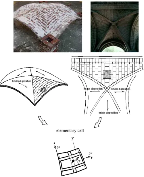
Figure 2.1: Typical double curvature shell structures (
Ω
) and different bricks dispositions.In this section, a FE procedure for obtaining in- and out-of-plane masonry failure surfaces in case of curved shells is outlined. A linearization with several planes of such surfaces will be then implemented in the 3D kinematic FE limit analysis code described in the following chapter for a kinematic limit analysis of entire masonry shells.
The general case of curved masonry vaults constituted by a finite number of infinitely differentiable surfaces fi
( )
x is considered (Figure 2.1 and Figure 2.2). Since in the homogenized FE procedure, plastic dissipation on the interfaces between adjoining elements can occur as a combination of in-plane actions, bending moment, torsion and out-of-plane shear, Reissner-Mindlin thick plate hypotheses are adopted (Cecchi et al. [10], Cecchi and Milani [11]). It must be noted that the introduction of a limited shear strength under out-of-plane actions could play an important role for instance in presence of monolithic arches and thin shells subjected to concentrated loads, for which failure can occur for out-of-plane sliding of the blocks, Figure 2.3 (Drosopoulos et al. [12]).Masonry is a composite material made by units bonded together with mortar joints. In most cases of building practice, units and mortar are periodically arranged, i.e. walls are constituted by the regular repetition of bricks bonded with joints. When dealing with flat panels, such periodicity allows to consider an entire structure
Ω
as the repetition of a suitable representative element of volume Y (REV or elementary cell) – see Figure 2.4. Y contains all the information necessary for describing completely the macroscopic behaviour ofΩ
. In particular, if a running bond pattern is considered, as shown in Figure 2.4, it has been shown that a rectangular elementary cell may be adopted.Figure 2.2: Typical double curvature shell structures
Ω
constituted by more that one infinitely differentiable surface (e.g.f
1, …f
4). In the figure principal curvature radii at apoint
P
are also represented (ρ
s andρ
r).Figure 2.3: Possible sliding of a thick arch.
On the other hand, when a curved masonry surface
Ω
, identified at a pointP
by the two principal curvatures 1/ρ
s and1
/
ρ
r Figure 2.2 is considered, it is very straightforward to conclude that it is not always possible to rigorously considerΩ
as a regular repetition of the elementary volume Y, thus precluding in principle the utilization of homogenization in the most general case. Nevertheless, a heuristic but technically suitable approach is to identify in any case a representative volume element, as depicted in Figure 2.4, which generates the double curvature shell by repetition.
Without loss of generality, let us consider a masonry shell constituted by a finite number of regular curved surfaces
Ω
. In correspondence of a point x ofΩ
, two versors r and s can be identified, corresponding to two orthogonal directions disposed parallel to the principal curvature planes of the vault in x, see Figure 2.4. Let the principal curvature radii along r and s be denoted withρ
s(x) andρ
r(x
)
respectively. Internal actions acting at each point
x
∈
Ω
are constituted by both in-plane (meridian, hoop and shear stresses) and out-of-in-plane (meridian, parallel bending and torsion) actions.When
ρ
r(x
)
→
∞
andρ
s(x)=ρ
s ∀x∈Ω, the special cases of cross vaults, barrel and cloister vaults are obtained. For all these cases of technical interest, the curved elementary cellY
shown in Figure 2.5 can be identified, which generates the curved surface by repetition.Furthermore, we define on
Y
the local curved frame of reference y1 − y2 − y3, with y3 normal to the vault middle surface,y
1 andy
2 parallel to r and srespectively (see Figure 2.4). For this special sub-class of problems, rigorous homogenization theory can be applied in combination with classic limit analysis theorems for the evaluation of the homogenized in- and out-of-plane strength domain Shom of masonry.
Despite the fact that classic homogenization theory has never been applied to masonry vaults, but only to flat walls, homogenization concepts has been recently used, for instance, by Slinchenko and Verijenko [13] for lattice shells of revolution,
for cylindrical shells by Andrianov et al. [14] and by Habbal [15] in the case of 1D wrinkled arches.
-a-
-b-
Figure 2.4: Comparison between homogenization procedure and the kinematic approach here proposed. – a: rigorous elementary cell identification in the flat case. –b: heuristic identification of the elementary cell for a double curvature masonry shell and kinematic
-a
-b
Figure 2.5:-a: Unit cell for a barrel vault with
ρ
s(x)=ρ
s =2m. –b: Arch (ρ
s =2 m) elementary cell and its discretization by means of 288 FE flat triangular elements.As a rule, when dealing with curved structures, equilibrium equations in the unit cell have to be written in a non Cartesian frame of reference, thus being substantially different with respect to the flat case.
The basic idea of the homogenization procedure consists in introducing averaged quantities representing the macroscopic membrane actions and strain tensors (respectively N and E) for in-plane actions, the macroscopic bending moment and curvature tensors for the out-of-plane problem (respectively
M
andχ
) and the out-of-plane sliding and shear (respectively Γ3 and T3) defined as follows (here the direction 3 is assumed perpendicular to the masonry middle plane, Figure 2.4): dV V E V ij =< >=∫
=[ ] ε 1 ε(u) E (i, j=1,2) dV V t N t V ij =< >=∫
= σ σ N/ [ / ] 1 (i, j=1,2) dV V V ij∫
∂ ∂ >= ∂ ∂ =< = y u ε y ε χ [χ
] / 1 ( ) (i, j=1,2) dV y V y M t V ij 3 3 1 ] [ / = =<σ >=∫
σ M (i, j=1,2)[
]
dV
V
y
u
y
u
y
u
y
u
V∫
>=
∂
∂
+
∂
∂
∂
∂
+
∂
∂
>=<
=<
3 3 1 1 3 3 2 2 3 3 31
/
/
;
/
/
γ
γ
Γ
[
]
dV V t V∫
>= >=< =< 3 13 23 3 3 1 ; / τ τ Tσ
σ
( 2.1)where V is the volume of the elementary cell, t the transverse thickness, u is the displacements vector (components ui), ε and σ stand for the local quantities
(stress and strain tensors with components εij and σij respectively) and <*> is the averaging operator. It is worth noting that, in this way, the behaviour of a moderately thick shell (Reissner-Mindlin hypotheses) may be modelled.
Anti-periodicity and periodicity conditions are imposed respectively to the stress field
σ
and the displacement fieldu
: ∂ ∂ + + + = Y Y on periodic -anti on ~ ~ ~ per per σn u u y Γ y χ y E u (2.2 ) where:
- uper stands for a periodic displacement field; - ∂Y is the cell internal boundary (see Figure 2.4); - E~ =
[
E O; OT 0]
(O is a 2×1 zero vector); -~
χ
=
[
y
3χ
O
(
1
/
2
χ
[
y
1y
2]
T)
T0
]
;- ~Γ is a 3 3 matrix with all zeros except Γ~31 =Γ3(1) and (2) ~
3 32 Γ
Γ = .
Let Sm, Sb and Shom denote respectively the strength domains of mortar (or more properly of the interface between mortar and bricks, see Lourenço and Rots [4]), of the units and of the homogenized macroscopic material. hom
S domain of the equivalent medium is defined in the space of the macroscopic stresses as follows (Suquet [16]):
[ ]
[ ]
( )
( )
∈ ∀ ∈ ∈ ∀ ∈ ∂ = = >= =< >= =< >= =< ≡∫
∫
∫
) ( ; ) ( on periodic -anti ) ( ) ( ) 3 ( 1 / ) 2 ( 1 / ) 1 ( 1 / | ) ( int 3 3 3 3 3 hom e Y S Y S d Y c b div a dV V t a dV y V y t a dV V t S b b m m V V V y y σ y y σ σn 0 n σ 0 σ τ τ T σ σ M σ σ N M T N ( 2.3 ) Here,[ ]
[ ]
σ
denotes the jump of micro-stresses across any discontinuity surface of normal nint. Conditions (a) is typical of homogenization, condition (d) is derived from anti-periodicity, condition (b) imposes the micro-equilibrium and condition (e) represents the yield criteria for the components (brick and mortar).The kinematic definition of Shom, used in this chapter, is obtained by means of the dual formulation of (2.3), assuming in the elementary cell a velocity field v equal to ~E&y+~χ&y+Γ~&y+vper, where D& is a macroscopic strain rate field, χ~ contains & the macroscopic curvature rate field, Γ~& contains the macroscopic out-of-plane sliding rate, andvper is a periodic velocity field. Under these hypotheses, the so called support function
π
hom can be evaluated as follows:( )
{
( )
per}
3 hom ~ ~ ~ | inf ~ , ~ , ~ v y Γ y χ y E v v Γ χ E v = + + += & & &
& & & y P π ( 2.4 ) Where
P
( )
v
is the power dissipated in the elementary cell for a given v.From (2.4), it has been shown that a kinematic definition of Shom can be obtained as follows:
(
)
( )
{
( )
( )
}
( )
( )
(
)
+ = + + + = = ∀ ≤ = + + ≡∫
∫
Y S T dS dY P y P S n v d v v y Γ y χ y E v v Γ χ E Γ χ E Γ χ E Γ T χ M E N T M N v ]]; [[ ~ ~ ~ | inf ~ , ~ , ~ ~ , ~ , ~ ~ , ~ , ~ 1 : : | per 3 hom hom hom π π π π & & & & & & & & & & & & & & & & ( 2.5 ) where:S is any discontinuity surface of v in Y, n is the normal to S;
(
[[
v
]];
n
)
=
1
/
2
(
[[
v
]]
⊗
n
+
n
⊗
[[
v
]]
)
π
;( )
d{
σ:d σ( )
y}
σ ∈S =max &; &π
;N,
M
andT
are the ultimate homogenized membrane, bending and out-of-plane shear actions respectively.It is worth noting that, using the kinematic definition given by (2.5), it is possible to explicitly determine the homogenized strength domain of masonry in the space of the macroscopic stresses using a FE limit analysis discretization of the elementary cell (Figure 2.4 -b).
In particular, Shom is obtained by means of the following constrained minimization problem:
( )
+ + + = = + + ∂ ∂ + ∂ ∂ = = ≡∫
) ( ~ ~ ~ ) ( 1 : : ) ( 2 1 1 min per 3 0 0 , , , hom c y b a y v y v d dV P V S T V i j j i ij per v y Γ y χ y E v Γ T χ M E N d 0 Γ χ E v & & & & & & & & & & &λ
( 2.6 ) where-
λ
is the kinematic limit multiplier of the assigned macroscopic actions (moments, membrane actions or out-of-plane shear);- M0, N0 and T0 are respectively unitary bending, membrane actions and out-of-plane shear tensors/vectors (i.e. they define only the direction in the Shom generalized stress space at which
λ
is evaluated, see also Figure 2.6)- P
( )
d& is the local plastic dissipation over the REV; -y
is a point of the REV in the local frame of reference.2.2
Derivation of masonry homogenized failure
surfaces by means of a FE discretization of the
unit cell
A strategy for obtaining an accurate estimation of Shom is to solve problem (2.6) for several assigned M0 - N0-T0 directions of the macroscopic actions by means of a limit analysis FE approach.
In what follows, a FE upper bound approach is adopted, in which dissipation occurs only at the interfaces between adjoining elements, both for in-plane and out-of-plane actions.
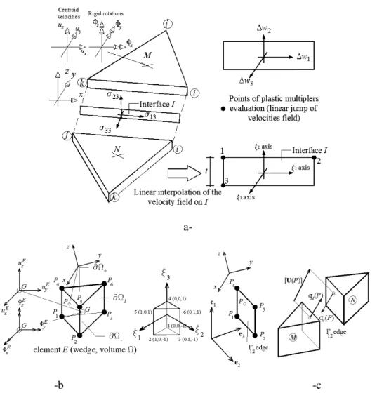
For the study of the masonry structures by means of shell elements (Chapter 3), the discretization of the elementary cell is with a triangular FE infinitely resistant elements, as shown in Figure 2.5-b; plastic dissipation can occur only at interfaces between adjoining elements.
-a
-b
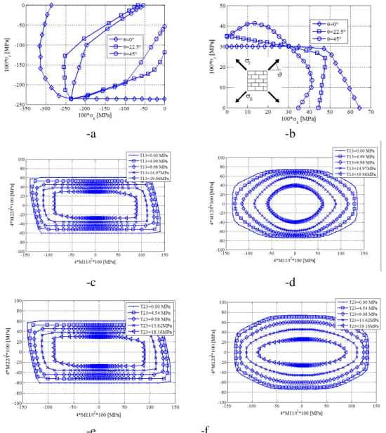
Figure 2.6: Meaning of N0, M0 and T0 -a vector
Σ
1 determines the optimization direction in the homogenized space of in- and out-of-plane actions. In this case( )
( )
[
]
T 0 0 0 sin cos 1 = α α KΣ ;-b vector
n
Σ determines, in this case,[
1 3 3 2]
0 n n ; n nΣ Σ Σ Σ = MInstead, for the whole structures studies with wedge elements (Chapter 4), the REV are discretized by means of 3D rigid infinitely resistant six-noded wedge elements, whereas mortar joints are reduced to interfaces with frictional behaviour and limited tensile and compressive strength (Figure 2.7). In this way, plastic dissipation may occur only at bricks-bricks interfaces and on mortar joints. Nonetheless, it is worth noting that, since 3D wedge elements are used at a structural level, only failure surfaces sections in terms of membrane and out-of-plane shear are needed, since flexural and torsional behaviour are derived directly at a structural level by means of an integration along the thickness. In any case, here both in-plane and out-of-plane failure surfaces are recovered for the sake of completeness.
Three different typologies of interfaces occur when a masonry elementary cell is considered, namely internal mortar-mortar, brick-brick and brick-mortar interfaces. Typically, cracking occurs in practice with a cohesive frictional behaviour at the interface between bricks and mortar or directly inside the joint. On the other hand, as experimental evidences show, sliding occurs in mortar joints with almost zero dilatancy with typical non-associated flow rule. This violates one of the hypotheses of classic limit analysis theory (see for instance Ferris and Tin Loi [17], Orduna and Lourenço [18] and [19]), implying that the uniqueness of the ultimate load may be lost and a multiplicity of solutions may exist for limit analysis problems, see for instance Begg and Fishwick [20].
On the other hand, classical limit analysis theorems assure the uniqueness of the ultimate load factor and lead to simple optimization problems. For the above-mentioned reasons, in this case associated flow rules are assumed for the constituent materials.
Figure 2.7: Simplified micro-mechanical approach adopted. Brick is supposed to interact
with its 6 neighbours and joints are reduced to interfaces with zero thickness. Then, brick with its neighbours is meshed by means of 6-noded wedges.
In general, any non-linear failure criterion
φ
=
φ
( )
σ
for mortar-mortar and bricks-mortar interfaces can be assumed. Nonetheless, as experimental evidences show, basic failure modes for masonry walls with weak mortar are a mixing of sliding along the joints (a), direct tensile splitting of the joints (b) and compressive crushing at the interface between mortar and bricks (c). These modes may be gathered adopting a Mohr-Coulomb failure criterion combined with tension cut-off and cap in compression, see Figure 2.8, as suggested by Lourenço and Rots [4]. For what concerns brick-brick interfaces, a classic Mohr-Coulomb failure criterion in plane stress (φ
b =φ
b( )
σ ) is assumed.Figure 2.8: Piecewise linear approximation of typical failure criterions adopted for joints
and brick-brick interfaces (respectively Linearized Lourenço and Rots 1997 and classic Mohr-Coulomb failure criterion).
Let us consider a generic interface
I
between adjoining triangular elementsM
a-
-b -c
Figure 2.9: (-a) Triangular three-nodes elements used for the FE discretization of the
elementary cell and identification of interface
I
frame of reference; (-b) Rigid infinitely resistant six-noded wedge element used for the REV discretization andΓ
12 interfacebetween contiguous elements (-c).
We denote with
ξ
1 −ξ
2 −ξ
3 an interface local frame of reference, withξ
3 axis perpendicular to the interface andξ
1−
ξ
2 laying on the interface plane.[
σ
33σ
13σ
23]
=
σ in Figure 2.9. is the stress vector field acting on the interface, with
σ
33 component normal to the interface (i.e. the stress acting parallel toξ
3 axis) andσ
13 andσ
23 the tangential stresses lying on the interface and parallel to axesξ
1−
ξ
2 respectively.Thus, for each triangular or wedge element, Figure 2.9, six velocities unknown are introduced, namely three centroid velocities (ux, u , y
u
z) along x,y
, z axes andthree rotations Φx, Φy,
Φ
z. Let us denote with(
)
[
]
T w w w1 2 3 2 1, ]][[w
ξ
ξ
= ∆ ∆ ∆ the jump of velocity field onI
, ∆wjcorresponding to the velocity jump along the direction j with respect to
3 2
1
ξ
ξ
ξ
− − . Trivial algebra permits to conclude that the jump of the velocity field[ ]
[ ]
w
is linear onI
.Aiming at treating the problem within the framework of linear programming, within each interface
I
of area AI, a piecewise linear approximation of the failure surfaceφ
=
φ
( )
σ
is adopted.φ
=
φ
( )
σ
is generally constituted by nlin planes of equationA
iITσ
=
c
iI1
≤
i
≤
n
lin. In Figure 2.8, for instance, two different linearized failure surfaces for both mortar-mortar interfaces and brick-mortar interfaces are shown.Since in the FE model adopted, the jump of velocity on interfaces is assumed to vary linearly, 3⋅nlin independent plastic multiplier rates are assumed as optimization variables for each interface.
Normality rule at the interfaces is expressed by three equality constraints per point of the interface, involving plastic multiplier rates fields I
( )
Pi
λ& and the jump of
( )
[ ]
( )
σ U ∂ ∂ =∑
=φ
λ
lin n i I i P P 1 ~ & ( 2.7 ) Where I( )
P i λ& is thei
thplastic multiplier rate field of
I
, associated with thei
thlinearization plane of the failure surface.
In order to satisfy equation (2.7) for each point of
I
, nine equality constraints must be imposed, i.e. it is necessary to evaluate (2.7) in correspondence of three different positions Pk =(
xk,yk,zk)
onI
(for instance atP
1,P
2, P5 ofΓ
12, Figure 2.9):( )
[
~]
( )
1,2,3 1 = ∂ ∂ =∑
= k P P lin n i k I i k σ Uλ
&φ
( 2.8) Where I( )
k i P λ& is thei
thplastic multiplier rate of
I
corresponding to point(
k k k)
k x y z
P = , , .
From equations (2.8) (2.7) and (2.6), internal power dissipated on the
I
thinterface is expressed by the following equation:
( )
∑ ∑
( )
∫ ∑
∫
= = = = ∂ ∂ = = lin I lin I n i I k k I i I i I A T n i I i I A T I A P c dA P dA P 1 4 1 1 int 4 1 )] ( ~ [λ
φ
λ
π
& & σ σ σ U ( 2.9 )It is interesting to notice from equation (2.9) that internal power estimation depends on plastic multiplier rates variables of points Pk only. Finally, it is
stressed that the set of plastic multipliers λiI
( )
P4& , obviously linear dependent with
respect to plastic multipliers of points
P
1,P
2 and P3, is introduced only for the sake of clearness.External power dissipated may be written as:
(
ΣT ΣT)
v ext 0 λ 1where Σ0 is the vector of permanent loads,
λ
is the load multiplier, T1
Σ is the vector of unitary loads dependent on the load multiplier (i.e. the optimization direction in the space of macroscopic stresses) and
v
is the assembled velocity vector of elements, which collects elements centroid velocities and rotations. Let us remark that, when dealing with masonry vaulted structures, dead loads play a crucial role and contribute in a not negligible manner to the external power. Obviously, periodicity conditions (2.6) are imposed onv
in the framework of classic FE procedures by means of standard Dirichlet boundary conditions (Pegon and Anthoine [2]).As the amplitude of the failure mechanism is arbitrary, a further normalization condition Σ1Tv=1 is usually introduced. Hence, the external power becomes linear in
v
andλ
and can be written as πext = ΣT0v+λ.Both by equations (2.7), (2.8), (2.9) and the kinematic formulation of limit analysis, the following constrained minimization problem is obtained:
( )