Abstract
At ENEA CR Brasimone a series of Large Scale Experiments (LSEs) in a Heavy Liquid Metal Pool (HLMP) will be performed, aiming to characterize the Steam Generator Tube Rupture (SGTR) event in relevant configuration for Heavy Liquid Metal Reactors (HLMRs). The assessment of the tube rupture propagation, damping effect of the surrounding structures, safety-guard devices, steam dragged into the main flow path and the investigation of the solid impurity formation and filter qualification, as a consequence of the SGTR phenomenon will be investigated.
The experimental campaign will be carried out in the CIRCE facility, the largest Lead-Bismuth Eutectic (LBE) alloy pool worldwide.
In order to properly take into account the not negligible above mentioned SGTR consequences, a proper test section (TS) will be designed, implemented and installed in the CIRCE pool. The test section will host a portion of a full scale bundle of a Primary Heat Exchanger (PHX).
The test section is mainly composed by a pumping system (jet pump driven by centrifugal pump), and four SGTR-TSs. Each SGTR-TS consists of a tube bundle relevant for the PHX.
The central tube of any SGTR-TS is filled by evaporating water flowing upwards and will be broken, by an external hydraulic system, causing the SGTR event. Four experiments are foreseen, in two different axial positon: middle and bottom. They are executed one at a time in the four SGTR-TSs.
Detailed pre-test analysis, performed by the SIMMER IV code, is reported. The results show that hazardous pressure peaks do not occur at the water injection start and that the cover gas pressurization could be maintained to a safe value (below 8 bar), by a 2 inch rupture disk set in the CIRCE dome, for a lapse of time higher than 15 s.
Index
Abstract ... 2 Index ... 3 List of figures ... 3 Abbreviations ... 4 1 Introduction ... 5 2 CIRCE facility ... 7 3 MYRRHA PHX ... 8 4 Test Section ... 9 4.1 General description ... 9 4.2 Tube Bundle ... 154.3 LBE Inlet Windows ... 16
4.4 LBE Outlet ... 16
4.5 Spacer Grid ... 17
4.6 Centrifugal Pump ... 17
4.7 Jet Pump ... 19
4.8 Venturi Flow Meter ... 19
4.9 Filtering Section ... 19
4.10 Distributor (Barrel simulator) ... 20
4.11 Separator ... 20
4.12 Cover Vessel ... 21
5 Detailed Pre Test Analysis ... 23
5.1 Introduction ... 23
5.2 Calculation domain ... 23
5.3 Obtained results ... 29
5.3.1 Transient period to reach operative stationary conditions ... 29
5.3.2 Water injection phase ... 32
6 Conclusions ... 34
References ... 36
List of figures
Figure 2.1: Overview of the CIRCE facility (from [3]) ... 7Figure 3.1: MYRRHA reactor overview (from [4]) ... 9
Figure 4.1: MAXSIMA test section, 3D top view ... 10
Figure 4.2: MAXSIMA test section, 3D bottom view ... 11
Figure 4.3: CIRCE and MAXSIMA test section, 2D vertical section (out of scale: height conserved, width enlarged 5 times) ... 12
Figure 4.5: Centrifugal pump ... 18
Figure 4.6: Jet Pump ... 19
Figure 4.7: LBE flow distributor (barrel simulator) ... 20
Figure 4.8: CIRCE Cover ... 22
Figure 5.1: Horizontal section of the test section, middle and bottom rupture models, zoom of tube bundle and water tube ... 24
Figure 5.2: SIMMER IV 3D view of the CIRCE vessel, tube bundle and water line (Sec. A-A Figure 5.1, middle rupture model) ... 25
Figure 5.3:Vertical sections of the experimental facility (A-A and C-C) ... 26
Figure 5.4: 3D view of the sectioned tube bundle and CIRCE vessel ... 27
Figure 5.5: 3D view of the top and bottom region of the tube bundle ... 28
Figure 5.6: Transient time history of the middle rupture scenario ... 29
Figure 5.7: Downwards LBE mass flow rate of the SGTR-TS ... 30
Figure 5.8: Drawing of the LBE velocity vectors ... 30
Figure 5.9: Downwards water mass flow rate in the tube ... 31
Figure 5.10: Drawing of the water velocity vectors ... 31
Figure 5.11: Pressure time trend in the CIRCE cover gas ... 32
Figure 5.12: Pressure time trends in the CIRCE bottom ... 33
Figure 5.13: LBE moved from the separator to the pool by injected vapour ... 33
Figure 5.14: Water mass flow rate injected into the LBE pool ... 34
Abbreviations
ADS Accelerator Driven System DHR Decay Heat Removal
EC European Commission
HLMFR Heavy Liquid Metal Fast Reactor HLMP Heavy Liquid Metal Pool
LBE Lead-Bismuth Eutectic LFR Lead Fast Reactor LSE Large Scale Experiment
MYRRHA Multi-purpose hYbrid Research Reactor for High-tech Applications PHX Primary Heat Exchanger
PP Primary Pump
RD Rupture Disk
SG Steam Generator
SGTR Steam Generator Tube Rupture
SGTR-TS Steam Generator Tube Rupture-Test Section
1 Introduction
The new generation Heavy Liquid Metal Fast Reactors (HLMFRs) and Accelerator Driven Systems (ADSs) are generally designed as a pool type reactor, implementing the Steam Generators (SGs) or Primary Heat Exchangers (PHXs) in the primary pool, in which also the core, primary pumps and main components are placed. This design feature allows the reactor performance to be increased and the whole layout to be simplified, making unnecessary an intermediate circuit. In such a configuration the secondary coolant (water), flowing into the heat exchanger tube bundle, at high pressure and sub-cooled conditions, could come into contact with the primary heavy liquid metal coolant, at a higher temperature and lower pressure, as a consequence of the SGTR phenomenon. That cannot be considered a zero-probability event, not even by adopting a double-wall-tube interposed between these two coolants.
During the SGTR event water enters the liquid metal pool in which it rapidly evaporates. The consequent sudden increase of the water specific volume entails pressure waves propagation and cover gas pressurization, which could affect the structural integrity of the surrounding structures or, in the worst case scenario, even damage the reactor core and/or vessel. Moreover, the rupture of a single SG tube could affect, in principle, the integrity of neighbouring tubes (domino effect), making the consequences of the accident scenario worse. The SG-shell constitutes an obstacle to the pressure waves propagation into the LBE melt, its dumping effect needs to be studied and calibrated in concert with the implemented safe-guard devices. Most of these are rupture disks and/or fast valves set on the dome of the reactor, flow limiters on the feed-water (Venturi nozzle) and SGTR detectors. The injection of water into the primary system entails the addition of a certain quantity of oxygen into the pool, becoming the responsible of pollution generation and thus primary system slug formation.
The SGTR event, therefore, should be considered as a safety issue in the design and in the preliminary safety analysis of LFRs. This requires the availability of qualified experimental data, having two main purpose: a) direct extrapolation to full scale nuclear plant conditions, if the facility geometry, configuration and the experimental initial and boundary conditions are properly scaled and representative of the reactor prototype; b) supporting the development and demonstrating the reliability of computer codes in simulating multi-fluid multi-phase problems by means of high-quality measurement data.
A test section hosting a portion of a full scale bundle of the reference PHX will be designed, implemented and installed in the CIRCE pool. The scheduled experimental campaign aims mainly to verify the integrity of the tubes surrounding the broken one, to investigate the pressure waves propagation, damping effect of the installed structures and plug formation.
The test section implements a jet pump driven by a vertical centrifugal pump aiming to provide the LBE flow rate. The jet pump aims to increase the LBE mass flow rate supplied by the centrifugal pump, converting pressure to kinetic energy. These two components were dimensioned to allow the feeding of a tube bundle composed by 4 ranks of tubes (called in the following SGTR-TS). The available space remaining in the CIRCE facility allows the positioning of four separated SGTR-TSs that are implemented symmetrically around the jet pump. The foreseen experimental campaign, therefore, has the objective of performing four separate SGTR tests, breaking down the central tube of each SGTR-TS one at a time. The SGTR-TSs are set in a cylindrical shell, absolving a dual task, aiming a) to define a separate pool determining inlet and outlet LBE flow and b) to constitute a structural damping barrier against the propagation of the pressure waves, to protect the CIRCE vessel’s structural integrity. The available LBE mass flow rate is sufficient to feed only one SGTR-TS at a time, therefore, four dedicated valves are designed to close three out of four SGTR-TSs, during the test execution on the remaining open one. A filtering section is implemented downstream the jet pump.
The water side is designed to work at 16 bar, it corresponds to the design pressure of the CIRCE vessel. Therefore, the facility integrity needs to be guaranteed by the implementation of properly sized safe-guard devices as rupture-disks or fast safety valves. The possibility to also implement a flow limiter on the CIRCE feed water is taken into account.
The four separate SGTR events are designed to be produced by four dedicated mechanical devices that pull up the central tube of the SGTR-TSs, in which the rupture zone is defined by a proper pre-cut. The four experiments are scheduled to investigate two different rupture positions on the PHX tube: bottom and middle location. Two tests are foreseen to be performed at each position to also provide data regarding the experimental repeatability. The lower rupture location is considered the most conservative condition.
This report briefly presents the CIRCE facility and describes in detail the SGTR test section in an almost definitive design status. Pre-test activity performed by SIMMER IV code is described and obtained results are presented.
2 CIRCE facility
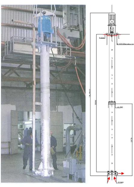
The CIRCE facility is located at ENEA research centre of Brasimone, Italy. It was originally designed to operate with lead-bismuth eutectic alloy and verify the key operating principles of the LBE-cooled concept of an 80 MWth Experimental Acceleration-driven System (XADS) [1]. CIRCE [2] consists of a full-height reduced diameter cylindrical vessel, 1:5 in comparison to the XADS vessel diameter. The main topics, the investigation of which motivated the CIRCE construction, are constituted by the LBE natural circulation, LBE coolant enhanced circulation by gas injection system, hydraulic characterization of the fuel assembly, thermal-hydraulic behavior of the target unit, performance of the secondary loop, instrumentation immersed in LBE and material corrosion in the pool with flowing LBE of controlled dissolved oxygen activity. The SGTR event, faced in this work, constitutes a hazardous issue to be taken into account.
An isometric view of the facility is shown in Figure 2.1. It is composed by three main vessels: the largest LBE pool worldwide S100 in which the experiments are carried out, the storage tank S200 that hosts the whole amount of LBE when the facility is not operational and the small intermediate vessel S300 that is adopted during the filling and draining phases of S100.
During the filling phase of S100, the LBE is gradually transferred by gravity from S200 to S300, and then the S300 cover gas is pressurized to provide the suitable pressure head needed to drive LBE into S100.
The main tank S100 is made of AISI 316L. The bottom and cylindrical shell (without the cover) have an overall height of 8500 mm, the external diameter and the thickness are 1200 and 15 mm, respectively. The maximum LBE inventory is about 90000 kg.
A system of heating cables, having an electric power of ~50 kW, is placed externally the S100 vessel and is able to maintain the LBE melt at about 300°C.
CIRCE S100 is designed to host different test sections hung to the cover vessel. In the framework of the SGTR experimental campaign a new cover vessel will be built to support the dedicated test section.
3 MYRRHA PHX
The PHX taken as reference is that of MYRRHA reactor. Highlighted by letter D in Figure 3.1. The LBE flow path is marked by black arrows in the same figure. The eutectic alloy increases in temperature flowing upwards through the core, it reaches the upper hot plenum exiting horizontally throughout the barrel openings, and then flows downwards passing into the PHXs transferring heat to the secondary loop. The cold LBE is then sucked by the primary pumps that inject it into the lower cold plenum, closing the primary coolant circuit.
Such a LBE flow path is strictly taken into account to properly design the SGTR test section to be implemented on CIRCE facility. Moreover, the PHX geometry and main parameters are partly conserved and partly scaled down coherently to the aim of performing SGTR experiments relevant to the MYRRHA configuration.
The MYRRHA design specifications foresee that the PHXs are able to a) remove the power generated during normal operation, b) remove the decay heat by natural circulation in Decay Heat Removal (DHR) conditions and eventually c) maintain the LBE in liquid state, heated by secondary water, during safe shutdown periods.
IN OUT IN
OUT
A Reactor Vessel F In-Vessel Fuel Handling
B Reactor Cover Machine
C Diaphragm G Core Barrel
D Primary Heat Exchanger H Above Core Structure E Primary Pump I Core Restraint System
Figure 3.1: MYRRHA reactor overview (from [4])
The LBE inlet and outlet temperature are 350°C and 270°C respectively. The water, at 16 bar, enters at 200°C and reaches saturation condition at 201.4°C.
4 Test Section
4.1 General description
The test section is designed to perform four SGTR experiments in a relevant configuration for MYRRHA reactor. The MYRRHA PHX characteristics are both conserved where possible and scaled down taking into account the volume available in CIRCE S100 vessel to host the test section. Indeed, the LBE mass flow rate is reduced proportionally to the partial PHX tube bundle simulated and the water side is constituted by only one water tube.
The test section is rigidly fastened to the dedicated cover vessel by bolted joints. Such a coupled structure could be removed only after draining all the LBE from the
S100 tank. This operation and the consequent refilling need several weeks to be completely carried out. Therefore, in reason of such a consideration, the possibility of performing one SGTR test, extract subsequently the test section to substitute the broken injection line (by the SGTR occurrence) and the test section re-setting into S100 so as to carry out other experimental campaign tests was not considered feasible. Therefore, the test section was designed to make the execution of the higher number (four) of tests possible without removing the cover vessel and connected experimental devices.
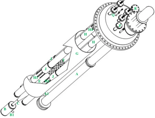
Two 3D views of MAXSIMA test section are shown in Figures 4.1 and 4.2 and one
E H1 A B B1 A1 C F G H H H1 J J J H4 P Q R
Figure 4.1: MAXSIMA test section, 3D top view
2D vertical and horizontal sections are depicted in Figure 4.3 (it is out of scale because it is enlarged five times to make a more detailed description of the SGTR-TS possible) and 4.4, respectively.
In Figures 4.1, 4.2, 4.3 and 4.4 the centrifugal pump is highlighted by the letter “A”. This component is able to provide a mass flow rate of ~50 kg/s at a LBE pressure
head of ~4 m. The pump discharge “A1” is connected by a flexible tube (not depicted in the figures), aiming to solve geometric inconsistencies, with “B1” tube that supply LBE driving fluid to the jet pump “C”, composed by the convergent “C1”, mixing “C2”
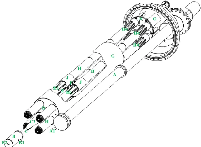
E A A1 B B1 C C3 B2 D F G H H H H1 H1 H4 H4 H4 J J N O
Figure 4.2: MAXSIMA test section, 3D bottom view
and divergent “C3” regions (Figure 4.3). The cylindrical component “B” constitutes the suction chamber into which the LBE enters from the CIRCE lower plenum through the bottom opening “B2”, which is sized to simulate the pressure drop occurring in the reactor core. Opening “B2” is therefore called core simulator.
The LBE flows upwards through the jet pump to provide the needed higher mass flow rate (more detail in the following). At the jet pump exit (upper position) a Venturi flow
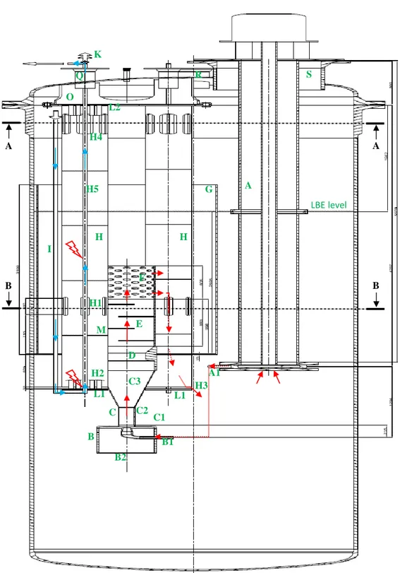
O Q C3 C2 C1 B B1 C B2 D B B A A H3 H2 E M L1 A1 A F G H H H1 H4 I LBE level H5 K L2 L1 R S
Figure 4.3: CIRCE and MAXSIMA test section, 2D vertical section (out of scale: height conserved, width enlarged 5 times)
allowing the centrifugal pump velocity regulation in order to reach the desired LBE flow rate. Downstream, a filtering section “E” is set and the total LBE mass flow rate passes through it. This component aims to quantify the pollution produced by the SGTR event. The reduction of pressure drops along the component “E” led to choose
a filtering section composed by filtering planes that do not close the whole horizontal section (Figure 4.3). Above, a perforated tube “F” having the same inner and outer diameter of the filter “E” is welded. The “F” component accomplishes the task of horizontally distributing the injected LBE, as it is carried out by the barrel component of MYRRHA design. The LBE reaches the separator component “G”, composed by a cylindrical shell closed at the bottom by a round plate (four small holes assure the correct execution of the draining phase). The separator defines a separate pool from the main CIRCE LBE melt. It is important to remark the existing thermal equilibrium of the LBE melt in any position inside the CIRCE vessel. Indeed, the melt temperature is set equal to the LBE inlet temperature in the PHX, that is 350°C. Such a decision aims to execute SGTR tests in the most severe conditions, which would cause, thus, higher and faster water vaporization. The heat exchange performance is not foreseen to be investigated.
The separator component hosts four SGTR-TSs “H”. Each of these test sections is composed by an external 6 inch tube ~5 m long, hosting a tube bundle of 31 tubes. Water flows upwards into the central tube and the surrounding ones are dummy tubes. The SGTR-TS aims to simulate a portion of the PHX of MYRRHA system. The water and LBE flow paths are highlighted by blue and red arrows respectively (dotted arrows indicate flows hidden behind a structural component) in Figure 4.3. Four separate feed water lines “I” pass the cover vessel through nozzle “P” (see Figure 4.1) and bring the water to the bottom of the lower tube plates “L1”, from which the water flows upwards. The descending tube “I” is thermally isolated from the LBE melt, aiming to avoid water boiling before reaching the heat exchange active length of the SGTR-TS, which starts above the lower plate “L1”. Thermal isolation is obtained by a double tube, the gap of which is filled by argon, being opened in the cover gas.
The SGTR-TS connects the LBE contained into the separator to the melt into the CIRCE pool, analogously to the MYRRHA PHX connecting the hot and cold plenum. The outgoing LBE from the SGTR-TSs is available to be sucked by the centrifugal pump and jet pump suction chamber “B2”, so that the system works continuously. The LBE flows from the separator into the SGTR-TS passing through vertical openings “H1”, simulating the LBE inlet windows of the PHX shown in Figure 3.1. The LBE flows downwards into 6 inch tubes “H”, shell side of the tube bundle, and goes out from a free radial opening “H3” performing the task of the PHX LBE outlet regions. The overall LBE mass flow rate, outgoing from the perforated tube, has to feed one SGTR-TS at a time, where the test is ongoing. Therefore, a closure system
constituted by sliding valves “J” is adopted to allow to the whole LBE stream to flow through one of the four SGTR-TSs.
The experimental campaign foresees to perform four experiments, one water tubes “H5” for each SGTR-TS. The rupture is caused in bottom position for the two inner SGTR-TSs and middle position for the two outer SGTR-TSs. The rupture of the water tubes is obtained by hydraulic devices that catch and pull up “K” the tubes, from the outside of the cover vessel. The positions in which the ruptures occur are precisely defined by the reduced tube thickness obtained by a circumferential notch performed by machine tools.
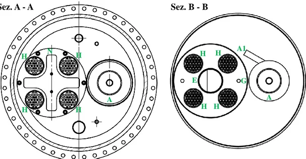
Figure 4.4 shows the horizontal sections A-A and B-B defined in Figure 4.3. In the section on the left, the upper part of the facility is viewed from the bottom, in which the four SGTR-TSs “H”, top plate “N” with six bolts and the centrifugal pump “A” are shown. The section B-B depicts the four SGTR-TSs “H” and respective spacer grids, the filtering section “E”, the separator “G” and the centrifugal pump “A”.
Sez. A - A Sez. B - B A A1 G H H A N H H H H H H E
Figure 4.4: CIRCE vessel and MAXSIMA-TS horizontal sections A-A and B-B
In Figure 4.3 two red lightings mark the position where the ruptures are scheduled to be performed. In spite of their positioning on the same water tube “H5”, which is done for simplicity, only one rupture occurs on each tube. Therefore, the two depicted ruptures at low and middle position affect two SGTR-TSs. Regarding the third and fourth SGTR-TS, the related water tubes are scheduled to be broken at a lower and middle position, so that the experimental campaign is also able to provide
experimental data about the repeatability of the tests. The lower rupture is located just above the lower plate “L1”, since this position has a high criticality from the point of view of stress corrosion cracking. The middle notch is set in the average position between two spacer grids, where the maximum tube deflection could occur.
The vapour produced by SGTR events flows outwards from the SGTR-TS by the upper windows “H4”, reaching the CIRCE cover gas and causing pressure increase. The released vapour could act on the tube bundle and structural components modifying the test section geometry and structural integrity. Moreover, the geometric stability of the test section needs to be maintained during the phase in which the water tube is pulled upwards. Therefore, sufficient test section stiffness needs to be achieved. This goal is pursued by welded connections between the tube bundle and the lower “L1” and upper “L2” tube plates, Figure 4.3, and thanks to the four spacer grids “M”. The SGTR-TSs are welded to the separator basis and plate “N” (Figure 4.2), that is in turn bolted to the upper structure “O” welded to the CIRCE cover. The water tubes are fastened by welding to the lower plate “L1” and are able to slide through the spacer grids, upper plate and cover vessel. In such a way they can be elongated by the hydraulic system to cause their rupture. After the rupture has been caused, the distance between the two faces of the double-ended guillotine break affects the amount of water injected into the CIRCE vessel. Therefore, such a distance value is limited by a pulling system implementing devices (limit switches) that impede further movement in either direction of the disconnected tube part, so that the opening through which the water flows outwards is precisely defined.
4.2 Tube Bundle
The main limit faced during scaling down the MYRRHA PHX, by a CIRCE test section, is constituted by the availability of a coherent LBE flow rate value. This value needs to be conserved during the definition of the test section. Consequently, the cross-sectional area of the flowing LBE into the experimental tube bundle has to be limited in agreement with the maximum available mass flow rate provided by the jet pump. This implies a limit on the number of ranks composing the experimental bundle. The nominal mass flow rate of the centrifugal pump is about equal to 50 kg/s with an exit pressure of almost 4 bar.
A sensitivity analysis was performed by CFD simulations to calibrate the jet pump, suction chamber and core simulator dimensions [5]. The obtained results showed a
maximum LBE flow rate of about 100 kg/s at the jet pump exit section, with a pressure head of about 1 bar.
Aiming to maintain a sufficient mass flow rate margin to compensate the pressure drops along the LBE loop, the tube bundle test section is composed by 31 tubes, having the same outer diameter, thickness and pitch of the PHX’s ones. They are installed into a standard AISI 316L 6” schedule 40 tube.
Four ranks of tubes are implemented. The outer one is not composed by the foreseen 18 tubes because the 6 tubes at the hexagonal vertexes are not employed. The tube bundle defined in such a way allows a LBE flow rate of about 80 kg/s that is conservatively in agreement with the amount of LBE provided by the pumps (~ 100 kg /s).
Water flows into the central tube “H5”. The first rank of tubes is filled by gas argon at 16 bar, continuously monitored. These six tubes are connected in the CIRCE dome by a gas manifold that brings outside the cover vessel the static pressure information. The outer tubes are drilled and filled by LBE, allowing high rigidity in the tube bundle and thus improving fragmentation of the vapour jet.
4.3 LBE Inlet Windows
The LBE enters into the PHX passing through eight openings called LBE inlet windows, see Figure 3.1. The approach is to conserve, in the experimental test the ratio between the overall area of the LBE inlet windows and the flow cross-sectional area. Such a value is ~4.4 and provides a precisely defined flowing area to realize the openings “H1” marked in Figures 4.1, 4.2, 4.3 and 4.4. Apparently, from the thermal-hydraulic point of view the only drawback of implementing the actual height of the LBE windows (1300 mm) in the SGTR-TS is constituted by the low width of the windows (high pressure drop) that would result assuming six openings. However, the mechanical operation of the closure system of SGTR-TSs, valves “J”, adopted to convey the overall LBE mass flow rate into only one test section out of four at a time, and also the limited space available in the CIRCE dome, to allocate the moving system of the closure valves “J”, impose the reduction of the windows height to the value of 200 mm.
4.4 LBE Outlet
The LBE exits from the bottom of tube bundle and enters the melt pool passing through a cylindrical free surface, defined by a diameter equal to the 6 in tube outer
diameter and a height equal to 33 mm. The PHX design foresees an higher LBE exit opening. The downscaling of this dimension, to almost one fifth, is based on the conservation, in the experimental test section, of the surfaces ratio between the exit radial surface and the horizontal free surface below the lower spacer grid. Maintaining the MYRRHA design value is not considered an acceptable choice, because, having an exit flow area too high in comparison to the LBE mass flow rate, vortexes at the outgoing region and consequent reverse flow into SGTR-TS could occur.
4.5 Spacer Grid
The geometric stability of the PHX tube bundle is maintained by rigid connection to the upper and lower tube plate and seven spacer grids, axially spaced ~1000 mm. On the basis of the overall LBE mass flow rate and the spacer grid free flow area, the LBE average velocity passing through a PHX grid is computed. This parameter is taken as reference to be preserved in the design of the LBE passage area of SGTR-TS spacer grid. Considering the tube bundle triangular pitch, the easiest and adopted distribution of the LBE passages is constituted by circular holes, positioned in the center of the triangles defined by the tubes of the bundle.
Fixed the LBE velocity and mass flow rate, the passage area is consequently defined. Moreover, adopting the described spatial distribution even the number of the passages is almost characterized. Therefore, the SGTR-TS spacer grids are designed to be passed by LBE flow through 58 holes of about 10 mm diameter.
4.6 Centrifugal Pump
The centrifugal pump, component “A” in Figures 4.1, 4.2, 4.3 and 4.4, is shown in detail by a picture and a technical drawing on the left and right respectively of Figure 4.5. The depicted red arrows show the LBE suction (vertical) and delivery (horizontal) flow. This component is currently available at the CR Brasimone. The centrifugal pump is composed by a top electric motor connected to a mechanical joint fastened to the pump shaft, moving in turn, the impeller hosted into the lower casing. The shaft pump is contained in an external perforated tube. The outgoing LBE from the pump, from element “A1” in the previous Figures 4.1-4.4, is conveyed to the jet pump injector “B1” by a flexible tube not shown in the figures. The pump is designed to provide LBE outlet mass flow rate and pressure of about 50 kg/s and 4 bar, respectively.
Figure 4.5: Centrifugal pump
The pump is bolted by its flange, positioned almost at the joint level, to the larger nozzle (~400 mm external diameter) of the cover vessel. Almost half pump shaft works in contact with LBE, because it is set into a holed external tube and immersed into CIRCE LBE pool. Moreover, the argon cover gas enters through upper holes into the pump column, therefore the pump needs to be isolated, aiming to maintain CIRCE pressurization and avoid any leakage of gas.
4.7 Jet Pump
The higher LBE mass flow rate provided by the centrifugal pump (~50 kg/s) is not sufficient to supply the needed LBE to feed the SGTR-TS (~80 kg/s). A jet pump is therefore implemented in the test section, aiming to increase the LBE flow rate.
A sensitivity analysis is performed by CFD code [5] to define the jet pump and opening “B2” (at the bottom of the suction chamber) dimensions, as shown in Figure 4.6. Opening “B2” is designed to simulate the pressure drops due to the flowing LBE through the reactor core, therefore it is called the core simulator.
The analysis was carried out aiming to maximize the outlet LBE mass flow rate, avoiding the pressure in the throat section to approach saturation value. The nozzle, throat and “B2”diameter, length of mixing, suction and diffusion chamber, LBE mass flow rate supplied by “B1” tube and the pressure head at the jet pump exit are parameters varied
during the sensitivity study. The obtained result is shown in Figure 4.6 and the computed LBE outlet mass flow rate is estimated to be ~100 kg/s.
4.8 Venturi Flow Meter
A Venturi flow meter is set above the jet pump, aiming to measure the LBE mass flow rate and provide useful feedback to the control system that regulates the pump velocity to maintain the desired (~80 kg/s) LBE mass flow rate flowing through the SGTR-TS. The inner diameter of the inlet region is equal to the exit jet pump diameter. This component is at present available at the RC Brasimone.
4.9 Filtering Section
The filtering section is welded to the outlet section of the Venturi tube. No difference between their internal diameters exists. The filtering column is composed by staggered filtering planes that do not close the whole LBE flow area. This choice aims to reduce the pressure drops that would occur adopting other kinds of filters, which close the entire flow section. The primary goal of the filtering section
B2
B1
implementation is constituted by the quantification of the impurities dispersed into the LBE flow, as a consequence of the SGTR phenomenon.
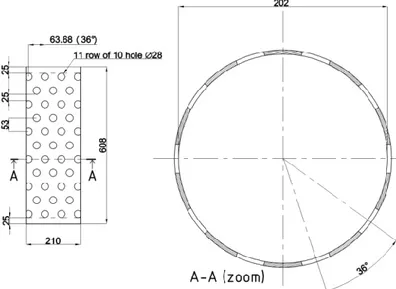
4.10 Distributor (Barrel simulator)
Similarly to the barrel component of the MYRRHA design, the test section foresees that the LBE is supplied uniformly to the separate pool (upper plenum in MYRRHA system), passing through a perforated tube.
The perforations are arranged on 11 rows, each one of which is composed by ten equidistant holes, as implemented in the MYRRHA design. The hole diameter and the interaxis between the rows of holes are calculated by an iterative procedure to maintain the same porosity of the MYRRHA barrel component (20%), which is calculated as the ratio between the overall holes surface and the unperforated barrel internal surface, related only to the barrel portion with holes. Conserving this value, the distributor results composed by holes 28 mm diameter with a distance of 53 mm between the rows of holes, as depicted in Figure 4.7. The entire component length (608 mm) is a consequence of the parameters cited earlier.
4.11 Separator
The separator component is a cylindrical shell 3100 mm height, closed at the bottom by a plate, having an outer diameter of 660 mm and four holes of 20 mm diameter dedicated to carry out the LBE drainage safely. This component defines the separate pool, (corresponding to the upper plenum of the MYRRHA design) receiving LBE from the jet pump and supplying it to the SGTR-TSs. This component also aims to
constitute a safety barrier against the pressure waves propagation toward the CIRCE vessel. The height of the LBE level in the separator shell is defined equal to the MYRRHA design value, 2595 mm. On the basis of this value, the separator height is designed to be 3100 mm, because such a defined difference prevents that the LBE escapes from the top of the separator, during the SGTR transient. Indeed, throughout the execution of the bottom rupture tests, it is reasonable to suppose that the vapour will flow upwards into the SGTR-TS blocking the descending LBE flow for a certain lapse of time, during which the LBE supplied by the pumps into the separator will cause a level increase.
4.12 Cover Vessel
The cover of the CIRCE S100 vessel is designed to support the whole MAXSIMA test section, by means of two main connections. The former is constituted by nozzle “S”, see Figure 4.8, which is designed a) large enough to allow the centrifugal pump to be inserted through the cover from the above and b) equipped by a flange allowing the bolted connection with the pump flange. Therefore, the relative position of the centrifugal pump and CIRCE vessel is defined. The latter connection is carried out by the “O” support, see Figure 4.8, that has the task of positioning the four SGTR-TSs, welded to the top plate “N” (Figures 4.2-4.4), that is in turn bolted to the flange of the “O” support. The four 6” tubes are rigidly connected to the separator and the vertical complex composed by jet pump, Venturi flow meter, filtering section and distributor. Therefore, the position of the mentioned components is also fixed.
Since the position of the centrifugal pump and test section simulating the MYRRHA PHX system are defined independently, geometric inconsistency could occur, as consequence of mechanical realization, between the centrifugal pump exit section “A1” and the inlet section “B1” of the jet pump injector, see Figure 4.3. Such considerations lead to use a flexible tube to connect “A1” to “B1” (not depicted in previous figures).
Figure 4.8 shows also a) four “Q” nozzles, hosting four outgoing water tube and four bars used to operate the closure valves “J”; b) “P” nozzle through which four tubes supplying water and four monitoring gas tubes pass; c) “R” nozzle allowing the passage of instrumentation cables; d) two “T” ½ in penetrations supporting Swagelok connectors, assuring the pressure sealing of two level gauges; and e) two “U” 1 in penetrations with Swagelok sealing, allowing the passage of two heater systems,
needed to maintain the LBE melt temperature (350°C) constant during the tests execution. S O Q Q Q Q R S P T1 T2 U1 U2 Q Q R T1
5 Detailed Pre Test Analysis
5.1 Introduction
The experimental campaign, characterized by the execution of SGTR tests in the CIRCE S100 vessel, needs to be supported by numerical simulations able to face multi-fluid multiphase problems. Among a wide range of available computer codes, the SIMMER IV was chosen to be adopted to support the whole experimental design phase and perform the pre-test activity, on the basis of its specific modelling capabilities of water-liquid metal interaction and 3D nature (Cartesian or cylindrical). This code will be used also to perform the post-test activity, aiming to define code limits and any possible needed improvements.
The tests are foreseen to be carried out performing the rupture of water (16 bar, 200°C) tubes immersed in the LBE pool (no significant cover gas pressurization, 350°C). It is essential to take into account that the CIRCE vessel is 15 mm thick and its design pressure is equal to the pressure of the injected water (16 bar).
The experiments are planned to be constituted by different phases. Initially, both the water and LBE independent circulations need to reach the stationary value (MYRRHA design) in terms of mass flow rate, pressure and temperature. Successively, the water tube is pulled upward and the obtained rupture injects water into the melt pool, starting the SGTR transient. During this phase, the pressure in the CIRCE vessel starts to increase and becomes indispensable to define the safety systems (rupture disks, water flow limiter), aiming to limit such pressurization to avoid consequences on the CIRCE vessel.
The SIMMER IV code is employed to simulate the pressurization transients into S100, following the SGTR events. The main goals of the simulations are constituted by the evaluation of a) the presence of hazardous pressure peaks, with higher probability at the water injection start instant; b) the grace period available to intervene before reaching the CIRCE design pressure; and c) the extended grace period obtained due to the implementation of rupture disks, having different sizes. Two SGTR scenarios (bottom and middle) are simulated by the SIMMER IV code.
5.2 Calculation domain
The numerical analysis of the SGTR phenomenon is performed, by Cartesian SIMMER IV code, modelling the whole and actual geometry of the CIRCE S100 vessel and the test section described in section 4 by a geometrical model of about
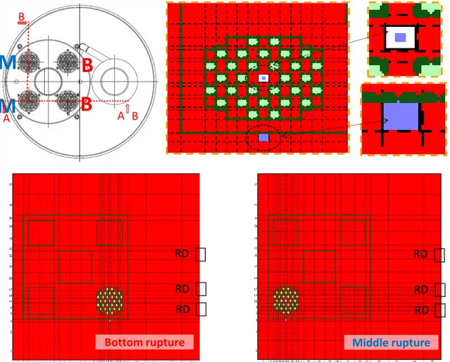
30000 cells. Due to the high calculation time needed by the 3D code and the investigated water-LBE interaction scenario, the model was developed aiming to reduce as much as possible the cells’ number, maintaining its capability to simulate the test section behaviour reliably. Therefore, two models were developed, for the bottom and middle rupture respectively, in each one of which only the tubes of the bundle affected by rupture were modelled, as shown in Figure 5.1.
Middle rupture RD RD RD Bottom rupture RD RD RD
B
M
B
M
B B A AFigure 5.1: Horizontal section of the test section, middle and bottom rupture models, zoom of tube bundle and water tube
Figure 5.1 depicts the LBE in red, liquid water in blue, steam in white and tubes of the bundle in light green. The dark green lines are virtual walls, positioned at the cells boundaries and avoid mass, momentum and energy exchanges. A zoom of the tube bundle is also shown with an additional zoom of the descending water tube (external to the bundle) and rising heated two phase tube (in the centre of the bundle) on which the rupture is caused. Three rupture disks are also highlighted on the models,
they are positioned in the cover gas region on the connections to three discharge lines as shown by three horizontal blue tubes in Figure 5.2.
Ar cover gas
LBE
H2O SGTR-TS TSFigure 5.2: SIMMER IV 3D view of the CIRCE vessel, tube bundle and water line (Sec. A-A Figure 5.1, middle rupture model)
In Figure 5.2 a 3D view of the section A-A, highlighted in Figure 5.1, is shown. It is possible to distinguish the LBE and cover gas volumes, the tube bundle, water line (blue and red arrows point out the entering and exit water line, respectively) and three horizontal discharge tubes connected to the rupture disks.
In the 3D views the virtual walls are not depicted by the graphical SIMMER IV tool. They are adopted to define the geometry of the separator, outer tube of the filtering section and of the SGTR-TSs, as shown in Figure 5.3. In which it is possible to observe the descending water line blue and the white ascending one with a narrow
blue line in the centre, representing the volume fraction of the water liquid phase. A zoom of the rupture region, 33 mm height, is also depicted. Section A-A and C-C show also the vertical geometry of the separator and SGTR-TS with and without tube bundle. Moreover, the openings allowing the LBE entrance into the separator and SGTR-TS, and the windows in the upper part of the SGTR-TS for avoiding the pressurization after the SGTR event are also shown.
section A-A section C-C Middle rupture Middle rupture C C A A Middle rupture RD RD RD 33 Ø 14 pump
Figure 5.3:Vertical sections of the experimental facility (A-A and C-C)
The graphical 3D tool of the SIMMER IV depicts models with different scales for the three coordinates. In the model it is possible to appreciate an enlarged water tube that would not be possible to distinguish by an in scale model representation.
The magnitude of the out of scale could be clearly understood considering that the CIRCE S100 vessel is ~9000 mm high and has an inner diameter of 1170 mm. Instead, in Figure 5.3 the wideness is higher than the height.
The decision to adopt the 3D Cartesian SIMMER IV code was forced by the significant asymmetry of the test section. Figure 5.4 shows the 3D view of section B-B of Figure 5.1, aiming to display the water line in blue.
LBE
Ar cover gas
H2O
Sezione B-B
Figure 5.4: 3D view of the sectioned tube bundle and CIRCE vessel
The centrifugal and jet pump are not simulated and the required LBE mass flow rate (80 kg/s) injected into the separator is generated by a pump set as shown by the yellow dotted rectangle in Figure 5.3.
The design value of the water mass flow rate (69 g/s) is obtained imposing a pressure difference between the water inlet and outlet and varying the pressure drop in a point as a regulation valve.
In the section A-A of Figure 5.3 the rupture position is highlighted with the relative zoom. In which it is possible to note the walls of the tube (black and green) able to exchange heat with the LBE. The tube has a rectangular section having the same flowing area of the real pipe. The 30 surrounding tubes are modelled as non-calculation regions (light green), they are shown by a 3D slightly out of scale view in Figure 5.5.
top
SGTR-TS
30 dummy tubes
1 water tube
bottom
Figure 5.5: 3D view of the top and bottom region of the tube bundle
In the performed simulations water is injected into the LBE region of PHX after about 40 s from the calculation start, see Figure 5.6. This time interval constitutes the transient period to reach operative stationary conditions, in terms of LBE and water mass flow rate through the PHX shell side and PHX water tube, respectively. The period of pressure increase in CIRCE vessel, red line in Figure 5.6, lasts up to the rupture disks activation. This lapse of time is almost equal to 7.5 s for the middle rupture scenario. The time interval during which the rupture disk is opened is shown by an orange line in Figure 5.6, after that, at about 54.5 s the water supply line is closed.
40 s
0 s
water injection
transient period to reach the MYRRHA PHX operative stationary conditions
t
rupture disk opened ~47.5 s ~54.5 s water supply closedFigure 5.6: Transient time history of the middle rupture scenario
5.3 Obtained results
In the following, the obtained SIMMER IV results are presented for the middle rupture scenario (the bottom rupture event will be reported in the next ADP activity). They are subdivided in two different subchapters. The former describes the numerical analysis referred to the lapse of time before the water injection, during which the stationary condition of water and LBE mass flow rates were reached. The latter presents the numerical results during the phase following the tube rupture.
5.3.1 Transient period to reach operative stationary conditions
The first phase (about 40 s) of the calculation period aims to reach the operative stationary conditions of the test section.
Figure 5.7 shows the computed LBE mass flow rate flowing downwards shell side of the SGTR-TS, the reached value is in agreement with the required one of 80 kg/s. Figure 5.8 depicts the qualitative distribution of the LBE velocity vectors in the SGTR-TS.
The computed water velocity in the descending tube (see Figure 5.9) is affected by an oscillation of about ±0.005 kg/s around 0.070 kg/s. Such an oscillation is considered acceptable. A 2D view depicting the water velocity vectors is shown in Figure 5.10.
(80 kg/s)
Figure 5.7: Downwards LBE mass flow rate of the SGTR-TS
(69 g/s)
Figure 5.9: Downwards water mass flow rate in the tube
5.3.2 Water injection phase
After reaching numerically, as far as possible, the stationary conditions analogous to those foreseen by design, the tube rupture is simulated (@ about 40 s). The computed pressurization transients in the cover gas and bottom part of CIRCE model are shown in Figure 5.11 and Figure 5.12, respectively. Their difference is due to the LBE head, affected by the shape and position of the LBE free level.
The pressure increases with an average gradient of about 0.65 bar/s, reaching the value of intervention of the rupture disk (6 bar) at about 47.5 s. In this instant one 2’’ discharge line was opened, maintaining the water supply line opened. The pressure began to decrease showing low pressure recovers. At about 54.5 s the water supply line was closed and the computed pressurization started to decrease, reaching 1.5 bar in about 15 s.
The lapse of time, about 7.5 s, needed to reach the rupture disk opening is plenty of time to carry out the test. Hazardous pressure peaks do not occur in the whole geometrical domain. The adoption of only one 2’’ rupture disk (three RDs are available on the experimental facility) appears therefore safe enough to avoid consequences on the CIRCE vessel.
2'' rupture disk opening
water injection start
Figure 5.12: Pressure time trends in the CIRCE bottom
t = 40.3 s t = 40.8 s
t = 41.5 s t = 41.2 s
Middle rupture Middle rupture
Middle rupture Middle rupture
The peak shown in Figure 5.12 at about 41.5 s is not computed in the cover gas. The reason of such a peak is due to the dynamic of the LBE contained in the separator that is moved upward and outside the separator by the vapor injected through the rupture. At the instant in which the LBE thrown out of the separator fall on the LBE free level of the main vessel (see Figure 5.13) its level increases causing an higher LBE head on the vessel bottom.
The water mass flow rate injected into the LBE pool is depicted in Figure 5.14. The peak at the rupture instant is about 1.4 kg/s and few seconds later a plateau of about 0.8 kg/s is reached up to the closure of the water line, when the water mass flow rate oscillates around zero, due to the water remained in the tube that evaporates and push part of the liquid water contained into the LBE pool.
water injection closure
water injection start
2'' rupture disk opening
Figure 5.14: Water mass flow rate injected into the LBE pool
6 Conclusions
The SGTR event is foreseen to be investigated at the ENEA CR Brasimone with a dedicated test section implemented on the CIRCE facility. In the framework of the PAR 2014 the detailed pre-test analysis of the foreseen experimental campaign was carried out by the SIMMER IV code. The experimental campaign aims to investigate
the consequences of the pressure waves propagation, dumping effect of the structural parts, tube rupture propagation to neighbouring tubes, the performance of safety devices, the steam trapping in the LBE flow and solid impurity formation after the SGTR occurrence.
This report describes the definitive design of the test section. It is composed by a) a centrifugal and jet pump providing the needed LBE mass flow rate to feed the PHX simulator, in which the SGTR events are scheduled to be performed; b) a cylindrical shell closed at the bottom called separator, in which the LBE is injected by the pump system, with the task of defining a separate pool from which the LBE enters the PHX simulator; and c) four separated PHX simulator, called SGTR-TS, each one of which is composed by a 6” tube hosting 31 tubes disposed in 4 ranks, the central one is the water tube that is planned to be broken by a mechanical system. The test section also hosts a filtering section. The water is supplied at 16 bar and 200°C, the LBE temperature is set equal to 350°C (the experimental campaign does not aim to characterize the heat exchanger performance).
This report also describes the execution of detailed pre-tests analysis performed by the SIMMER IV code for the middle rupture scenario. The bottom rupture event will be issued in the framework of the next PAR. The 3D geometrical model is described, focusing on the water injection line and LBE flowing shell side of the tube bundle. The water tube rupture and consequent water injection was carried out after reaching the stationary condition of water and LBE mass flow rate. The water injection entails a cover gas pressurization that reaches 6 bar (value of rupture disk activation) in about 7.5 s. The discharge reduces the pressure slowly, up to the closure of the water injection line that coincides with the stop of the water injection. Hazardous pressure peaks are not numerically predicted. The computed water mass flow rate shows an injection peak of about 1.4 kg/s and a later plateau of about 0.8 kg/s before to decrease to zero.
The higher computed pressure is well below the design value of the CIRCE vessel, therefore a 2” rupture disks appears large enough to avoid consequence on the CIRCE main vessel. The consequent grace period (before to close the water line) is predicted to be at least equal to 15 s, which is considered enough to stop or reduce the water supply. The SIMMER results show also that the calculated pressure peaks, occurring at the initial phase of the water injection transient, do not reach alarming pressure values.
References
1. L. Cinotti et al., “XADS Pb-Bi Cooled Experimental Accelerator-driven System - Reference Configuration - Summary Report”, ANSALDO ADS1SIFX0500, Rev.0, June 2001.
2. P. Turroni, L. Cinotti et al., “The CIRCE Test Facility”, ANS Winter Meeting, Reno 12-15 November 2001.
3. M. Tarantino, “Integral Circulation Experiment: Thermal-Hydraulic Simulator of a LFR Primary System”, ENEA report, NNFISS-LP3-004, 23 September 2010. 4. MYRRHA Team, “MYRRHA Technical Description”, SCK-CEN report, October
2011.
![Figure 2.1: Overview of the CIRCE facility (from [3])](https://thumb-eu.123doks.com/thumbv2/123dokorg/5614870.68304/7.892.223.667.662.1109/figure-overview-circe-facility.webp)
![Figure 3.1: MYRRHA reactor overview (from [4])](https://thumb-eu.123doks.com/thumbv2/123dokorg/5614870.68304/9.892.103.794.83.721/figure-myrrha-reactor-overview-from.webp)