Stephen J. McPhail
Angelo Moreno
Emanuele Belella
Lorenzo Abate
Viviana Cigolotti
THE NEW FUEL CHAIN
FROM RENEWABLES TO FUEL CELLS
Hyd rogen Fu
el Ce
Advanced Fuel Cells Implementing Agreement Annex 33 – Stationary Applications
Stephen J. McPhail, Viviana Cigolotti, Lorenzo Abate, Emanuele Belella, Angelo Moreno
2016 ENEA
National Agency for New Technologies, Energy and Sustainable Economic Development
C
ONTENTS
1. INTRODUCTION ... 5 1.1 Renewable energy and waste management ... 7 1.2 Greenhouse gases and emissions ... 8 2. FUEL FOR THOUGHT ... 11 2.1 THE BIOMASS CONTEXT... 11 2.2 BIOMASS CONVERSION ... 12 2.3 LIQUID BIOFUELS AND THEIR PRODUCTION PROCESSES ... 13 2.3.1 Biodiesel ... 13 2.3.2 Bioethanol ... 14 2.3.3 Biomethanol ... 15 2.3.4 DME ... 16 2.4 GASIFICATION AND ANAEROBIC DIGESTION ... 16 2.4.1 Biosyngas ... 16 2.4.2 Biogas ... 17 2.4.3 Biohydrogen ... 18 3. FUEL CELLS ... 21 3.1 DIRECT FUEL CELLS ... 22 3.1.1 SOFC ... 22 3.1.2 MCFC ... 23 3.1.3 DMFC ... 24 3.2 HYDROGEN FUEL CELLS ... 25 3.2.1 PEMFC ... 25 3.2.2 AFC ... 26 3.2.3 PAFC ... 27 4. FUEL PROCESSING ... 29 4.1 BIOMASS TO FUEL CELLS – THE MISSING LINK ... 29 4.2 CLEAN‐UP OF BIOGAS FOR FUEL CELLS ... 29 4.3 CLEAN‐UP OF BIOSYNGAS FOR FUEL CELLS ... 30 4.3.1 Removing Particulate Matter ... 30 4.3.2 Removing Tars ... 31 4.3.3 Removing Sulfur compounds ... 32 4.3.4 Removing Hydrogen Chloride ... 33 4.3.5 Removing Alkali metal compounds ... 33 4.3.6 Suggested configuration for a cleaning system ... 33 4.4 Concluding thoughts ... 34
5. REAL APPLICATIONS ... 35 5.1 IEUA REGIONAL WASTEWATER TREATMENT PLANT 1 (RP‐1) ... 35 5.2 SIERRA NEVADA BREWERY ... 36 5.3 DUBLIN SAN RAMON WASTEWATER TREATMENT FACILITY ... 37 5.4 TULARE WASTEWATER TREATMENT PLANT ... 38 5.5 Renewable Hydrogen From Tri‐Generation Fuel Cells Included Under California Low Carbon Fuel Standard (LCFS) ... 39 5.6 BIOCELL ... 40 5.7 SOFCSYNGAS SRL ... 41 5.8 ENESYSLAB ... 43 5.9 Metacon ... 44 5.10 DEMOSOFC ... 45 References ... 47
1. INTRODUCTION
Rising world population and progressing urbanization with higher living standards will determine a significant growth in energy demand in the foreseeable future. Though not equally acted upon everywhere, it is widely acknowledged that the depletion of conventional fuel resources and the growing impact of global productivity on our society and habitat call for more efficient energy production systems, utilization of renewable sources, reduction of greenhouse and toxic gases emissions and smarter exploitation of primary fuels.
Projections show that though energy demand in OECD (Organization for Economic Cooperation and Development) countries is expected to remain almost constant, whereas non‐OECD demand could come to double that of the former by 2030 (Figure 1).
FIGURE 1 OECD and Non OECD Energy Demand (ExxonMobil (2013))
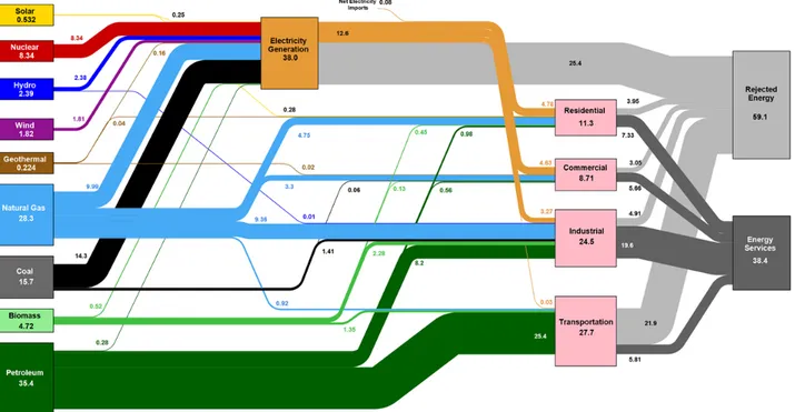
How and where is this energy consumed? Taken over all OECD countries, the way our energy flows from the source to end use is qualitatively very much like the United States’ picture in Figure 2. The values can be roughly taken to be percentages of total energy consumption. What we can see in this chart is that electricity is a very important intermediate energy carrier, consuming nearly 40% of all primary energy. Electricity is also generated from a wide variety of fuel sources and is then distributed equally over the residential, commercial and industrial sectors, but its overall generation efficiency is quite low, rejecting over two thirds of the incoming energy. The transport sector is seen to rely heavily on petroleum‐based fuels (gasoline, diesel and jet fuel), and to perform even more dramatically in terms of energy efficiency, where only about one fifth of the incoming energy actually provides the service of transportation.
FIGURE 2 U.S. energy use (LLNL (2016)), taken as a representative example of energy flows in the OECD
Electricity generation is expected to grow by 50 percent from 2010 to 2040 (Figure 3), driven above all by demand in the industrial and residential/commercial sectors, and will be increasingly realized with renewable energy flows like wind and solar. But to be able to provide reliable, continuous power to an ever growing customer base, electricity generation will always need a large store of readily convertible, sustaining and sustainable, substance‐based fuel to meet demand.
In a scenario where coal combustion needs to be phased out due to climate issues and where the technologies for the extraction of natural gas become more complex and expensive, biomass and waste are natural and immediate substitutes. Above all, waste and residual biomass are a widely distributed byproduct of human activity that is often considered a burden both in economic and environmental terms, but that could be readily transformed in a capillary availability of dispatchable energy. This booklet sets out the basics of a new fuel chain: where biomass and waste convert to electricity cleanly, at high efficiencies and with minimal environmental impact, everywhere where it is needed.
FIGURE 3 Energy demand by sector (ExxonMobil (2013))
1.1
R
ENEWABLE ENERGY AND WASTE MANAGEMENTIt is impossible to ignore, today, the importance of renewable energy technologies, and their multiple roles in: Compensating depletion of fossil fuel resources Reducing greenhouse gas emissions Improving energy security Creating jobs.
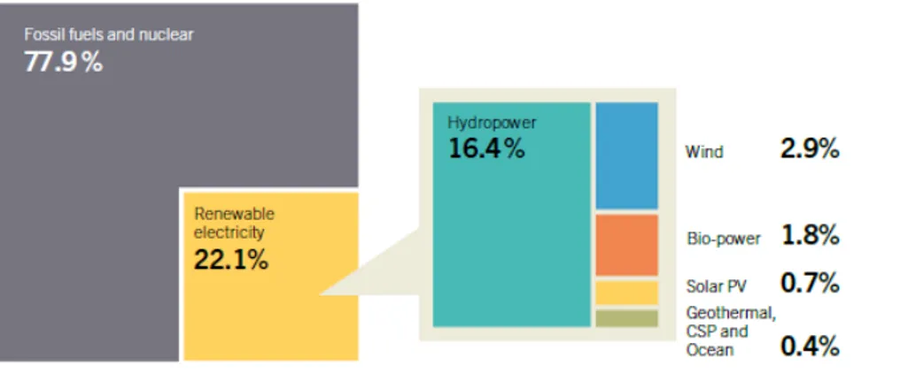
Renewables provided an estimated 19% of global final energy consumption in 2012 (9% from traditional biomass, 10% from modern renewable). Around the world there are major differences in the use of biomass. Currently, most of the energy from biomass is still simply burning wood for domestic heating and cooking in developing countries, where it contributes some 22% to the total primary energy mix. In OECD countries renewable electricity is predominantly generated by hydropower and wind (Figures 4 and 5). However, the projections made for the European Union Renewable Energy Road Map1 (January 2007) suggest that the use of biomass can be expected to
double, contributing around half of the total effort to reach the 20% renewable energy target in 2020.
FIGURE 4 Estimated renewable energy share of Global energy consumption, 2012 (REN 21 (2014))
FIGURE 5 Estimated renewable energy share of Global Electricity Production, end 2013 (REN 21 (2014))
Biomass is a versatile, renewable, widely available and potentially sustainable energy source as well as being practically carbon neutral. The technical and economic potentials of biomass are considerably than what is currently consumed, and their availability is evenly distributed in all countries. These two concepts are fundamentally important because they imply:
the possibility to gain energetic (and consequently economic) independence of all countries from monopolizing primary fuel exporters
potentially rapid, versatile and differentiated development of improved technologies with better efficiencies, reducing greenhouse gas emissions
a virtuous cycle, that increases minimization and valorization of waste to produce energy and resources where they are needed.
1.2
G
REENHOUSE GASES AND EMISSIONSSince 2000, an estimated total of 420 billion tons CO2 has been cumulatively emitted due to human
activities (including deforestation). Scientific literature suggests that limiting average global temperature rise to 2 °C above pre‐industrial levels – the target internationally adopted in UN climate negotiations – is possible if cumulative emissions in the 2000–2050 period do not exceed 1,000 to 1,500 billion tons CO2. If the current global increase in CO2 emissions continues, cumulative emissions
will surpass this total within the next two decades.
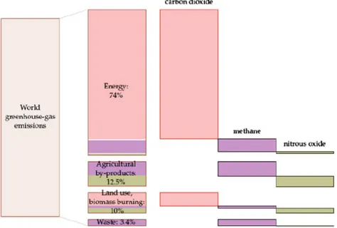
In Figure 6 the breakdown by sector is given of worldwide CO2 (equivalent) emissions, where those
related to the Energy sector include also Transportation: it is clear that the lion share of greenhouse gas (GHG) emissions results from our needs for heat and power and mobility. However, the emissions caused by agricultural activities and waste management are by no means negligible. This further underlines how improved valorization of organic waste streams (both urban and rural) could lead to a double‐edged positive effect, compensating part of the emissions caused by the Energy and Transport needs as well as substituting part of the energy required by these.
FIGURE 6 Breakdown of world greenhouse gas emissions by cause and gas type in 2000 (MacKay (2008))
An important aspect, especially in densely populated areas, is localized emissions of toxic and acidifying gases: particulates, NOx and SOx, generated in all combustion processes, are posing severe threats to the quality of life in cities (especially cars, but also household boilers, power plants and other engines contribute to urban pollution). The price of fossil fuels and combustion‐based technology does not take into account these long‐term effects, which incur significant healthcare costs to society. Internalizing this cost in fuel retail price could make a significant difference to the economy of energy conversion. The incurred health costs reported in Table 1 are related to power plants equipped with the best available control technologies (i.e. including flue gas desulphurization, electrostatic precipitators and low‐NOx burners) and do not take into account the GHG effects of CO2
emissions, the costs of which, taken globally, are likely to be practically equal to those caused by the localized pollutants (SO2, NOx, particulates) combined. Health costs due to oil‐fired power plants are in
between those of coal‐fired and gas‐fired plants. The values are significant in terms of the retail prices of electricity (9‐30 €c/kWh in Europe in 20132) and exceed the fuel cost alone, both of coal
( ̴ 1 €c/kWh) and natural gas ( ̴ 0.07 €c/kWh).
Table 1. Health costs in Europe due to power plants (McPhail (2014), Rabl and Dreicer (2002))
Siting
Unit health costs (€c/kWh)
PCSC with FGD (coal) NGCC
SO2 NOx PM10 Total NOx
Typical 1.0 3.2 0.3 4.5 0.11 Urban 1.6 4.8 0.9 7.3 0.17 Rural 0.7 2.2 0.1 3.0 0.08
Thus, there is vested interest in using fuel conversion processes that are as clean as possible, especially in those appliances that are widely distributed among the population, above all in urban areas. We shall see that fuel cells are intrinsically clean power generator devices, and exceedingly suitable for distributed, small‐ and medium‐scale generation, when and where it is needed.
2. FUEL
FOR
THOUGHT
2.1
THE
BIOMASS
CONTEXT
EU Directive 2009/28/EC defines biomass as “the biodegradable fraction of products, waste and residues from agriculture (including vegetal and animal substances), forestry and related industries, as well as the biodegradable fraction of industrial and municipal waste”. There are thus several types of biomass. They can be divided into: Energy crops: herbaceous, woody and aquatic crops dedicated to the harvest of energy. Agricultural residues and waste: crop waste and animal waste. Forestry waste and residues: mill wood waste, logging residues, trees and shrub residues. Industrial and municipal wastes: the organic fraction of municipal solid waste (OFMSW), sewage sludge and waste from the food and drinks industry.
Biomass‐derived fuel continues to receive much interest due to its abundance, versatility, capillary distribution, potential neutrality in terms of greenhouse gas emissions as well as providing a new stimulus to the agricultural sector and rural economy.
Biomass‐derived fuels are either liquid or gaseous, hence easy to transport. Moreover, the production and utilization of biomass‐derived fuels have well‐developed and economically feasible technologies and infrastructure, so that further growth of their utilization is not hampered by structural limitations. The end use of biomass in the fuel chain can be both for transport and for power generation –even for the synthesis of new materials (biochemistry and biorefineries). Considering liquid biofuels for transport (more details in Section 2.3), biodiesel is largely used in the European Union, with an incorporation rate in the overall transport fuel of 4% in 2009. The most utilised form of biofuel for transportation in the world, however, is bioethanol, either from sugar cane or from corn. It is used massively in Brazil, where it is mixed in regular unleaded petrol in proportions up to 25%, but big consumers are also the European Union and the United States.
For power generation, biomass is usually either burned or gasified (in the case of solid and woody biomass) or decomposed to form biogas, a methane‐rich gas which can either be used directly for generation or be upgraded to biomethane, so that it can be injected into the natural gas grid. At the moment the use of biogas in transport is limited to one country (Sweden, 0.3%), however, for stationary heat and power generation biogas is becoming an ever‐growing intermediate, largely thanks to combined necessity of adequately dealing with growing amounts of organic waste. All over the world, municipal waste‐water treatment plants already use anaerobic digestion to stabilize the organics‐laden stream and produce high‐heating value biogas in the process. More details are given in Section 2.4.
A fundamental condition for the sustainable use of biomass is however that it be sourced and converted locally, given that its energy density is low (compared to fossil energy carriers) and the energy lost in moving it around wastes much of its energy potential. On the other hand, being both a spontaneous commodity and inherently associated with human activity (in terms of food production, cultivation of primary materials, organic waste, forestry products, etc.) biomass is widely and equitably distributed. Thus, collection points for biomass conversion should necessarily be decentralized, thereby also benefiting local participation and productivity. Finally, economic and
environmental burdens associated to the management of organic waste could be turned into profitable enterprise with modern technologies for energy valorization, yielding a sustainable solution to the growing waste problem.
Biomass promotes improvements in energy security and trade balances, as well as reductions in waste management and disposal problems and the creation of a local network for the production of biofuels, facilitating a smooth transition from “open” to “closed” resource cycles. Forward‐looking investments in bioenergy are therefore strategic in boosting local economy as well as in achieving a sustainable global energy policy.
T
HE GENERATION GAP IN BIOFUELSBiofuels that are produced from organic commodities that are also used for food production are called first‐generation biofuels. In addition to biogas, biodiesel and bioethanol are some of the most commercially used first‐generation biofuels. They are made from the sugars and vegetable oils found in arable crops, which can be easily extracted using conventional technologies. On the contrary, advanced biofuels, also referred to as second‐generation biofuels, do not compete with food. They are produced by innovative processes mainly using lignocellulosic biomass, harder to extract, for which commercial utilization is still under development. Advanced bioethanol, syngas and DME are some examples of second‐generation biofuels.
Where first‐generation biofuels have been most successfully deployed to date (as in Brazil, US, Germany, China), the infrastructure and markets have become well developed. This includes storage, distribution and transport of the biofuels as well as the adoption of standards.
The availability of land for the production of biofuels from dedicated energy crops may be limited, also to avoid competition with food, and requires careful assessment of the long‐term impact of land use change, in terms of soil nutrients, carbon and water resources, biodiversity, but also socio‐political effects.
An added characteristic for second‐generation biofuels is therefore that it should be produced from available agricultural, industrial and forestry residues that, on the other hand, are a readily available feedstock that can be purchased at its opportunity costs and would in many cases form a low‐cost if not a negative‐cost feedstock. Assuming even a conservative value of 10% availability of global agricultural and forestry residues for second‐generation biofuel production, there should be enough feedstock remaining for traditional uses (e.g. as fodder, organic fertiliser, domestic fuel).
2.2
BIOMASS CONVERSION
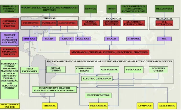
Biomass can be classified according to its main physical (and chemical) characteristics, which relate to: moisture content, calorific value, proportions of fixed carbon and volatiles, ash/residue content, alkali metal content, cellulose/lignin ratio. Without dwelling on the details of each of the aforementioned features, suffice it to say that these properties lead to requiring different biomass processing technologies for the conversion to a manageable fuel:
Thermal:
Pyrolysis: thermochemical anaerobic decomposition of organic material at tempera‐ tures between 250 °C and 500 °C.
Gasification: thermochemical partial oxidation process in which organic substances (e.g. biomass and coal) are converted into gas through a gasifying agent (air, steam,
oxygen, CO2 or a mixture of these). The product is syngas, a high‐heating value mixture
of H2, CO and other gases.
Combustion: a high‐temperature exothermic reaction between a fuel and an oxidant, which is not relevant for fuel cell applications. For this reason, combustion will not be treated here.
Biological
Fermentation: a metabolic process that converts sugar to acids, gases or alcohol in the absence of oxygen.
Anaerobic digestion: a collection of processes by which microorganisms break down biodegradable material in the absence of oxygen. The product is biogas, consisting of methane, carbon dioxide and traces of other ‘contaminant’ gases.
Mechanical extraction of bio‐oils
An overview of these methods and their end products are shown below in Figure 7.
FIGURE 7 Biomass energy conversion processes (Bocci et al. (2014))
2.3
LIQUID
BIOFUELS
AND
THEIR
PRODUCTION
PROCESSES
Compared to gaseous energy carriers, liquid fuels are easier and safer to handle, store and transport and have greater energy density, making them ideally suited for mobile or remote applications.
2.3.1 B
IODIESELA substitute for conventional diesel, biodiesel is produced by a chemical reaction between an animal fat or a vegetable oil mechanically extracted from raw biomass and an alcohol such as (bio)methanol or (bio)ethanol. Compared to petroleum diesel, biodiesel is non‐explosive, biodegradable and non‐ toxic. Yet it can be pumped, stored and handled using the same infrastructure, devices and procedure usually employed for conventional diesel fuel. Its drawbacks relate to chemical instability, high viscosity and low volatility as compared with fossil diesel.
FIGURE 8 General cost breakdown for production of biodiesel (Atabani et al., (2012))
Feedstock alone represents 75% of the overall biodiesel production cost (Figure 8). Hence, the choice of the cheapest feedstock is vital to ensure low production cost of biodiesel.
Currently, more than 95% of biodiesel is produced from edible oils such as rapeseed (84%), sunflower oil (13%), palm oil (1%), soybean oil and others (2%). Nevertheless, the use of this first‐generation biofuel raises major environmental concerns such as the destruction of vital soil resources and deforestation and many concerns about the competition of fuel versus food. Some of the sources for biodiesel production from non‐edible oils are Rubber Seed Tree (Hevca Brasiliensis), Sea Mango (Cerbera Odollam), Tobacco seed (Nicotiana Tabacum L.), Rice bran, Silk cotton tree (Ceiba Pentandra), Jojoba (Simmondsia Chinensis),
Animal fats such as beef tallow, poultry fat and pork lard, waste oils and grease are also considered second‐generation feedstocks. More recently, microalgae have emerged to be the third‐generation of biodiesel feedstock. Microalgae have the potential to yield up to 25 times the oil production of palm trees (currently possessing the highest oil yield at 5000 kg of oil per hectare) and 250 times the amount of soybeans. Moreover, they are easier to cultivate than many other plants.
2.3.2 B
IOETHANOLThe most promising liquid fuel that can be derived from biomass and organic waste is ethanol. Ethanol is an alcohol conventionally made through the fermentation of plant sugars from agricultural crops and biomass resources. The most common agricultural crop currently utilized for its production is corn: only in 2009 the USA produced 11 billion gallons of corn‐based ethanol. Moreover, ethanol production from biomass produces residuals that can be used for animal feed, corn oil, or other products. However, energy crops for ethanol production imply the sacrifice of arable land. The integration between anaerobic digestion treatment (for producing biogas, see Section 2.4) and the ethanol production process benefits both environment and energy supply: in fact, anaerobic digestion contributes to the reutilization of wastes as fertilizer or animal feed, and it is possible to win ethanol from the residues of this process, thus minimizing ecological footprint. Ethanol has a high H:C ratio: hence it is light but, as a liquid, it also has high volumetric energy density. It is easy to produce, safe to handle, transport and store, constituting a perfect hydrogen carrier for fuel cells. Its excellent chemical properties are matched by its ease and safety of handling, making it
suitable for low‐cost, capillary distribution, for adoption at a multitude of end applications. In fact, it is significantly less toxic than methanol and it is generally free of sulfur, which is a catalyst poison both in chemical processes, such as the reforming of hydrocarbons, and in electrochemical devices such as fuel cells. The theoretical quantity of hydrogen that can be produced from ethanol is furthermore almost double that of methanol, which is good news for the diffusion of hydrogen‐powered, low‐temperature fuel cells. The direct use of bioethanol as a fuel for high temperature fuel cells such as MCFCs and SOFCs increases the potential and efficiency of converting energy, thanks to a good balancing of the chemical and electrochemical processes within these cells with this fuel. With relatively minor further investment, bioethanol used in fuel cells will create substantial financial opportunities, as well as energy and environmental progress for the future. The production process for bio‐ethanol is shown in Figure 9.
FIGURE 9 Bioethanol production from lignocellulose biomass. Possibilities for reaction–reaction integration are shown inside
the shaded boxes: SSF – simultaneous saccharification and fermentation; SSFC – simultaneous saccharification and co-fermentation. Main stream components are: C – cellulose; H – hemicellulose; L – lignin; G – glucose; P – pentose;
I – inhibitors; EtOH – ethanol, (Balat (2011))
2.3.3 B
IOMETHANOLMethanol, also known as methyl alcohol, is the simplest existing alcohol, allowing high yields from its production feedstock. Currently more than 75% of methanol is produced from natural gas and coal, which are non‐renewable feedstocks. Alternatively, renewable biomethanol can be produced from biomass, such as wood and agricultural waste, by steam gasification, pyrolysis, or partial oxidation. Currently, renewable methanol is less popular because of its high production costs, due to less mature production techniques. Nevertheless, bio‐methanol and bioethanol have been the most commonly used biomass‐derived fuel for fuel cell systems for the past decade and will continue to play an important role in the near future.
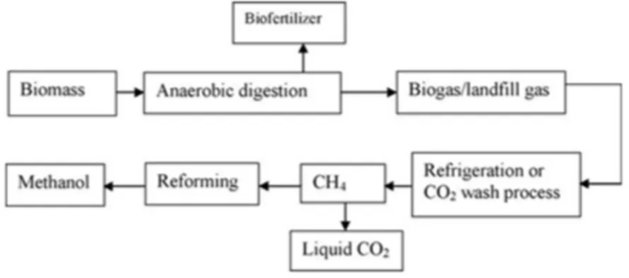
Production of methanol as liquid has several advantages such as low sulphur and low ash content. By using lignocellulosic biomass from wastes through anaerobic digestion process it is possible to generate liquid fuel and bio‐fertilizer for agricultural production. Figure 10 shows how anaerobic digestion can lead to the production of methanol.
FIGURE 10 Anaerobic digestion followed by reforming process for production of methanol
2.3.4 DME
DME (dimethyl ether) is a clean, colourless gas easy to liquefy (at the modest pressure of 5atm), store and transport. World production today is primarily by means of methanol dehydration, but DME can also be manufactured directly from synthesis gas produced by the gasification of coal or biomass, or through natural gas reforming. Among the various processes for chemical conversion of natural gas, direct synthesis of DME is the most efficient. Like ethanol and methanol, DME lacks a carbon‐carbon bond, enabling nearly complete oxidization in low‐temperature PEM fuel cells. On the other hand, DME has a higher energy density (8.2 vs. 6.1 kWh kg−1), is less toxic and can be conveniently stored and transported using existing infrastructures and technologies, being similar to gasoline. Therefore, the use of DME can potentially combine the advantages of easy fuel delivery of pressurized hydrogen, and the high energy density storage of liquid fuel. Moreover, recently direct DME fuel cells (DDMEFC) are being investigated, showing performances similar to direct methanol fuel cells.2.4
GASIFICATION AND ANAEROBIC DIGESTION
2.4.1 B
IOSYNGASSyngas (synthesis gas) is a mixture of H2, CO, CO2, N2 and small particles of char (solid carbonaceous
residue), ashes, tars and oils. It can be produced in several ways, but a particularly interesting process for capturing biomass energy is (thermal) gasification, or the release of heating value from solid fuel in the form of a high‐quality fuel gas by heating the biomass in sub‐stoichiometric conditions. Reactions take place at a range of pressures that run from atmospheric pressure to 33 bar and at high temperatures (between 500 and 850° C). Gasification steps are shown below in Figure 11, which usually take place within a single reactor.
FIGURE 11 Gasification process steps The most common reactors are fixed or fluidized bed gasifiers. Up to 85% of the original dry biomass is converted into fuel gas with a lower heating value (LHV) ranging from 4 MJ/Nm3 (air gasification) to 12 MJ/Nm3 (oxygen or steam gasification). While the use of oxygen or steam as a gasifying agent raises the heating value of the syngas produced, the processes to procure these require energy as well (with an air separation unit or a water evaporator) so that these have to be taken into account in the overall efficiency of syngas production. Accordingly, only in some circumstances oxygen is the better choice, whereas the heat for water evaporation can largely be recuperated from the (exothermal) gasification process itself, maximizing efficiency. Biomass gasification can be well integrated with MCFC or SOFC (molten carbonate or solid oxide fuel cells), due to their ability to convert the carbon monoxide in syngas as well as their being well‐ matched with the gasification process in terms of operating temperatures (600‐800 °C).
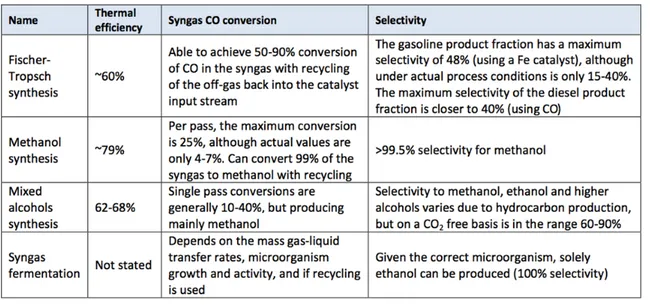
As a rich and reactive energy carrier, syngas can be either directly exploited for power generation or converted into liquid form in several ways, as shown in Table 2.
TABLE 2 Syngas-to-liquid processes (E4Tech (2009))
2.4.2 B
IOGASBiogas is predominantly constituted of methane (50–70%) and carbon dioxide (20–40%), but also contains traces (1‐5%) of other elements, such as ammonia, nitrogen, mercaptans, indolum, skatolum, halogenated hydrocarbons, siloxanes and hydrogen sulphide. The biogas has a LHV of about 21 MJ/Nm3 depending on its ultimate composition, which in turn depends on the biochemical composition of organic matter used and on the digestion technology and the operative conditions adopted. Biogas can be used directly in high temperature fuel cell (MCFC or SOFC) systems after an in‐
depth cleaning step for the removal of contaminants (especially Sulphur compounds). Alternatively, the biogas is upgraded in a further transformation step (e.g. to biohydrogen or biomethane). Biogas upgrading essentially consists of removing the carbon dioxide constituent, enhancing the energy content of the gas and increasing downstream conversion performance or storage efficiency.
At present, there are three basic methods used commercially for removal of carbon dioxide from biogas, either to reach vehicle fuel standard or to reach natural gas quality for injection to the natural gas grid: scrubbing, pressure swing adsorption and membrane separation.
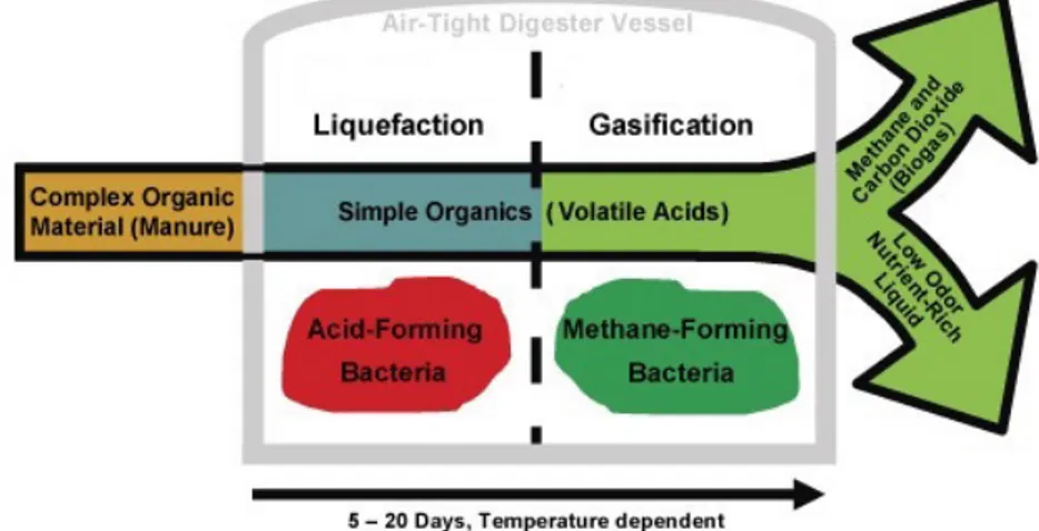
Anaerobic digestion is especially effective on biomass substrates with high organic loads such as animal farming effluents, wastewater from food processing industry (olive mill wastewater, dairy sludge, brewery residues, sea food processing wastes, etc.), slaughterhouse wastes, agricultural residues, organic fraction of municipal solid waste (OFMSW), residual algae, freshwater biomass, terrestrial weeds, etc. The digestion process, in addition to yielding valuable fuel, stabilizes the organic waste making it safer for disposal and handling. In fact, the digestate residue is viable as a fertilizer for reinsertion into the biomass growing cycle. An overview of the process is given in Figure 12 below.
FIGURE 12 Digestion processes steps
Currently, many countries are cultivating dedicated energy crops, like maize and sorghum, for biogas production; this practice is under critical observation, as it implies either a change in land use (with uncertain long‐term impact on local habitats) or competition with food crops required for nutrition of men and animals. In Europe, Germany is the country that experienced the greatest development of anaerobic digestion plants in the last ten years, particularly in the field of animal‐farming. In 2009 there were about 2,700 existing plants with an electric power installed of about 665 MW (Massi et al. (2012)), but these numbers have been and are still steadily increasing. Operating the biogas plants in co‐digestion mode (i.e. digesting different substrates together) increases the yield and seasonal stability of biogas composition and availability and is the preferred set‐up of plants operated in the bioenergy sector.
2.4.3 B
IOHYDROGENBiohydrogen can also be produced directly, without resorting to a hydrocarbon intermediate (such as methane), both through thermochemical and biological methods.
Hydrogen production from thermochemical processes has already been shown to be an economically sound and feasible choice. However, the produced hydrogen gas is usually contaminated by other constituents of the biomass source. Thus, for use in fuel cells (especially low‐temperature fuel cells) the hydrogen would have to be separated and purified. The different pathways leading to the final production of bio‐hydrogen are listed in the flowchart in Figure 13.
FIGURE 13 Hydrogen production technologies from various biomasses
The biological processes for direct hydrogen production from biomass are: Direct and indirect biophotolysis
Biological Water gas shift Photo‐fermentation Dark fermentation
Hydrogen‐producing enzymes, such as hydrogenase and nitrogenase, control all these processes. Direct biophotolysis uses microalgae, such as green algae and Cyanobacteria (that directly decompose water into hydrogen and oxygen in the presence of light by photosynthesis), to convert solar energy into chemical energy in the form of hydrogen. Recently the overall solar conversion efficiency has risen to 10% favored by the higher hydrogen production of mutant microalgae (Ni et al. (2006)). Biological Water‐gas shift is also still under development. It uses photoheterotrophic bacteria, such as Rhodospirillum rubrum, which can survive in the dark by using CO as their carbon source. This is a promising technology, as it is cost‐efficient compared with thermochemical water–gas shift processes due to the elimination of reformers and associated gas processing equipment. Photo‐fermentation is a process allowed by photosynthetic bacteria that are able to produce hydrogen through their nitrogenase that use solar energy and organic acids or biomass. Due to several drawbacks related to the low solar energy conversion efficiency and demand for elaborate anaerobic photobioreactors covering large areas, however, it is not yet a competitive alternative for hydrogen production.
Dark fermentation is the fermentation by anaerobic bacteria as well as some microalgae, which can produce hydrogen especially in the dark. The products of dark fermentation are mostly H2 and CO2
combined with other gases, such as CH4 or H2S, according the reaction process and the substrate used.
The benefit of dark fermentation is that solar radiation is not a requirement, hence hydrogen production does not demand much land and is not affected by the weather, for the benefit of the overall commercial value proposition.
3. FUEL
CELLS
Fuel cells are highly efficient electrochemical converters which extract the chemical power of a fuel and directly and very efficiently transform it into electrical and thermal power. They are silent and work without vibrations, as there are no moving parts nor combustion involved. This makes it also possible to achieve very low emissions of nitrogenous and sulphur compounds and fine particulate, strongly reducing their local environmental impact. In fact, the afore‐mentioned gases are among the most harmful that are currently emitted by conventional technologies such as the internal combustion engine (ICE). Thanks to their modularity, fuel cells can provide reliable energy for a wide range of power requests:
Portable applications for consumer electronics such as laptops, smartphones and cameras, back‐up power and remote power (15% of global residential electricity consumption in 2015, expected to become 45% by 2030)
Transport, in terms of fuel cell electric vehicles (FCEV) and auxiliary power units (APU) for on‐ board generation of electricity on vehicles of any kind
Stationary power production, with regards to combined heat and power units (CHP) or tri‐ generation units (combined heat, power, cooling).
Fuel cell technologies are classified according to the employed electrolyte, which defines their names and operating temperatures (Figure 14), hence the range of applications and fuels.
FIGURE 14 Overview of the different fuel cell technologies, operating temperatures and ions promoting the reaction3
The efficiencies of several FCs and other kinds of converters are compared in Figure 15.
FIGURE 15 Comparison of electric efficiency vs. power installed for combustion-based systems and fuel cell systems
The features of the different technologies of fuel cells are generically resumed and compared in Table 3, with particular attention to gas compositions and pollutants tolerances.
TABLE 3 Characteristics and tolerance limits of different Fuel Cells (Bocci et al. (2014))
A brief introduction to the different technologies can be made by discerning between direct and hydrogen fuel cells, respectively the ones capable to directly extract the hydrogen contained in several types of fuel, and the ones which need an external unit for processing the fuel in order to be fed exclusively with hydrogen. The FCs are presented in descending order of operating temperatures)
3.1
DIRECT
FUEL
CELLS
3.1.1 SOFC
Solid oxide fuel cells (SOFC) are able to reach very high and constant electric efficiencies from the scale of megawatts to a few watts, even at partial load (40% to over 60%). Fuel flexibility, low emissions of
NOx, SOx, particulate and CO2, vibration‐free operation are intrinsic features of this technology..
Additionally, their solid‐state, ceramic electrolyte guarantees ease of shaping and fabrication, and the absence of corrosive liquids make the SOFC one of the most promising configurations of fuel cells with a surprisingly wide range of applications. The working temperature ranges from 600 °C to 900 °C, allowing internal reforming of fuel, which is a key‐feature of SOFC. In fact a number of fuels can be fed directly to the device for electrochemical conversion: natural gas, ethanol, biogas, ammonia; or with minimal pre‐reforming (propane, LPG (liquefied petroleum gas), diesel, jet fuel, hydrazine). A fuel cleanup process (removal of poisoning agents often present in biofuels) is crucial for smooth and reliable performance,. In sharp contrast with combustion‐based technologies, which can reach 55% electrical efficiency only at extremely large scales (>GW), SOFC have constant, high efficiencies, and can be used for remote power applications (with a higher energy density and autonomy than actual Li‐ ion based batteries), in auxiliary power units (APU), in backup applications such as uninterruptible power supplies (UPS), for stationary combined heat and power generation in small scale (m‐CHP) or large scale (CHP). Moreover, as the waste heat is at high temperature, a bottoming cycle can be performed in order to further increase the efficiencies, or high‐quality process heat can be exploited.
FIGURE 156 Apple 10 MW SOFC farm made up of 50 Bloom Energy boxes rated 200kW each in Conover, North Carolina4
3.1.2 MCFC
The molten carbonate fuel cell (MCFC) operates at a temperature of about 650 °C, at which the electrolyte is in a liquid form as the name suggests. This brings several advantages compared to lower temperature fuel cells, such as less expensive catalysts to work properly (such as Nickel instead of Platinum) and higher tolerance to impurities. Furthermore, it can be fed with any kind of gaseous fuel containing hydrogen and carbon dioxide, as the nickel‐based electrodes, thanks to the high temperature, perform the so called “shift reaction” that releases hydrogen. As carbon dioxide is both a reactant and an end product, there are also interesting solutions for carbon capture and storage. The only other end product is high temperature steam, exploitable for additional electrical energy production (if a bottoming cycle is performed), or even for domestic heating. The inner fuel flexibility allows for the use of biogas, natural gas, syngas, gasified biomass, and even liquid ethanol, all after a cleanup process for abatement of poisoning particles.
MCFC is a reliable solution mostly addressed to steady‐state power generations, showing exceptionally high efficiencies in cogeneration mode (up to 90%, 48‐49% of which being electrical power) even in partial load. Moreover, MCFC power plants achieve an average availability of 95%, which makes them perfectly suitable for base‐load power.
FIGURE 17 The world’s largest fuel cell plant. 58.8 MW molten carbonate fuel cell park in Whasung City, Gyeonggi Province,
South Korea (courtesy of FuelCell Energy Solutions)
3.1.3 DMFC
Direct methanol fuel cells (or direct alcohol fuel cells, DAFC) can use liquid methanol directly as their fuel. Methanol is undoubtedly one of the best hydrogen carriers together with ethanol, as it is cheap and its energy density is analogous to gasoline, higher than every hydrogen storage option. The key advantage is its ease of transport and its stability in all environmental conditions. It is toxic, but hydrogen suffers from many other safety issues. At a working temperature of 60‐100 °C the more relevant downside is that reactions are much slower with methanol than with hydrogen, so DMFC efficiencies are remarkably lower than e.g. PEMFC (both use a proton exchange membrane as electrolyte, which makes them comparable). Once problems about safety, efficiency and costs will be solved, DMFC could compete with actual Li‐ion batteries in every aspect, from mobile electronics to vehicles. Additionally DMFC can be recharged quickly, simply pouring some methanol in.
FIGURE 18 EFOY pro2400 DMFC generator provides 110 W of electrical power, suitable for home needs5
3.2
HYDROGEN
FUEL
CELLS
Where pureness of the fuel is crucial, further equipment is necessary for gas cleanup. This is necessary for low temperature FCs, such as those based on polymer electrolyte membranes. They are characterized by rapid start‐up and shutdown periods, excellent load following capability and are ideal for small stationary, portable power and transport applications. A long‐standing downside, however, has been the need for an established hydrogen infrastructure to become effective for these technologies to become widely used. This is currently being tackled by concerted, strategic actions at interstate level both in Europe and in the USA, to accompany the increased deployment of these highly flexible fuel cells.
3.2.1 PEMFC
Polymer electrolyte membrane fuel cells (PEMFC, also called Proton exchange fuel cells, PEFC) employ pure hydrogen as their fuel, platinum‐catalyzed electrodes, and use a solid‐state membrane as the electrolyte, which needs to be continuously hydrated to perform well. Hence, water management is fundamental. The electrolyte imposes working temperatures of about 60‐80 °C, or up to 150 °C for high‐temperature PEMFC, developed to be more robust and require less Platinum. For the PEMFC, extreme pureness of hydrogen is essential, since CO, ammonia, halogens and sulfur compounds are poisoning agents. Water is the only liquid phase in the cell, thus corrosion is minimal. Since the operating temperatures are low, start‐up is very rapid. Also, achievable power densities are very high. Consequently, the main uses of PEMFC are for mobile applications (forklifts, buses, bicycles, boats, etc.), and for fuel cell vehicles (FCVs). The latter are currently being pushed by all major car manufacturers and rapidly gaining interest in the field of personal transport.
FIGURE 19 London bus on the RV1 line, powered by Ballard FC Velocity-HD6 PEMFC modules delivering 150 kWe6
3.2.2 AFC
The Alkaline fuel cell uses hydrogen as fuel and pure oxygen as oxidant, and the only byproduct is water. In its most widely used version the electrolyte is a porous matrix filled by an aqueous KOH solution at different concentrations, from 85wt% for high operating temperatures (250 °C) to 50wt% for low temperatures (100 °C). Cell costs are low, compared to other systems, both for electrodes and electrolyte, even if the balance of plant (BoP) must include highly effective CO and CO2 removal
systems if ambient air is used as oxidant, due to the extreme sensitivity to carbon. Moreover, unlike PEMFC, AFC usually do not have bipolar plates, which means lower cost but also lower power densities. On the other side water management is far easier for AFC. The main application of AFC has historically been for space vehicles (Apollo space missions of NASA in the 1960’s). Today this device could be considered for lower‐power CHP systems and any mobile application including hydrogen vehicles, but further research efforts have lagged behind in recent years.
FIGURE 20 AFC module used by NASA for the space shuttle Apollo7
3.2.3 PAFC
Phosphoric acid fuel cells work by means of a proton conducting liquid electrolyte, namely 100% pure phosphoric acid contained in a porous silicon matrix. This acid reduces the water vapor pressure so water management in the cell is easier than PEMFC (see below). Hydrogen is the fuel, whilst either ambient air or pure oxygen can be adopted as the oxidant, the latter giving the best performances. The operating temperatures are around 150‐220 °C, which allows for a good tolerance to CO (up to 1%). Sulfur compounds as H2S are poisoning, albeit the tolerance is higher than for PEMFC and AFC. Yet, the working temperatures are low enough to allow for the use of common construction materials, except for graphite separator plates for containing of the highly corrosive liquid electrolyte. PAFCs are mostly used for stationary applications; system efficiencies are about 40% (lower than high‐temperature FC but higher than low‐temperature FC), and the waste heat can be used for cogeneration or for a bottoming Rankine cycle.
FIGURE 21 DOOSAN PureCell System 400 CEP provides 440 kW of stationary clean electrical power, operating on natural gas8
7 www.fuelcell.no 8 www.doosanfuelcell.com
4. FUEL
PROCESSING
4.1
BIOMASS
TO
FUEL
CELLS
–
THE
MISSING
LINK
Fuel cells are intrinsically clean power generators, not only because of the elegant process of electrochemical oxidation that avoids combustion and its byproducts, but also because they are highly sensitive catalytic devices. In particular low‐temperature, hydrogen fuel cells are intolerant to H2S, CO,
CO2, CH4 and NH3 and are thereby ill‐suited for compound fuels such as biomass‐derived gases. On the
other hand, the high temperature at which direct fuel cells operate allows them to internally reform compound fuels such as biogas and syngas, and to increase tolerance against contaminants, while maintaining high electrical efficiency (close to 50%). However, this tolerance level is still very low compared to combustion engines and the presence, in the raw produced gas, of poisonous substances for the FC, like particulate and specific organic and inorganic impurities, oblige to have a tailor‐made gas clean‐up system downstream the fuel section, before FC alimentation. Many gas cleaning systems are available, but in this chapter only the main methods are illustrated – subdivided into “cold” technologies for biogas clean‐up and “hot” technologies for biosyngas clean‐up – to underpin the importance of this step in the biomass to fuel cell chain. It should be noted that by thoroughly purifying the fuel gas before entering the fuel cell, the emission of harmful compounds to the atmosphere after conversion is automatically avoided, guaranteeing a clean environment around the area. The issue of toxic and acidifying emissions is thereby resolved at the source, and the fuel cell system thus becomes conspicuous by the absence of any localized impact on the surroundings in terms of exhausts and noise.
4.2
CLEAN‐UP
OF
BIOGAS
FOR
FUEL
CELLS
Biogas is the result of spontaneous decomposition of organic matter in absence of air – and close to ambient temperatures – to methane and carbon dioxide. Depending on the substrate that decomposes, different other compounds make up the balance (see Table 4), with different effects on the operating fuel cell. Being a low‐temperature product, biogas is usually purified with ambient‐temperature processes, which is advantageous in terms of simplicity as well as effectiveness where physical (adsorptive) methods are applied: the low mobility of the gas molecules at low temperatures makes it easier to trap selected compounds on specific adsorbent materials.
TABLE 4 Biogas average composition (Bocci et al. (2014))
CH4 CO2 O2‐N2 H2S hydrocarbons Halogenated VOC Siloxanes NH3 LHV
(%vol) (%vol) (%vol) (ppmv) (%vol) (mg/Nm3) (mg/Nm3) (ppmv) (MJ/Nm3)
50‐80 30‐50 0‐10 0‐4000 1‐5 5‐300 0‐50 100‐2000 18‐28
Of the trace compounds listed in Table 4, hydrogen sulphide (H2S) is by far the most common and the
most lethal for the fuel cell system. However, it is easily removed by conventional methods such as adsorption on activated carbons or zeolites: these highly porous materials carry out in‐depth filtering of the highly reactive H2S but need to be replaced when saturated. Though 100% effective, this
approach leads to a constant amount of waste production which is not ideal in terms of economics or sustainability. Biological systems are being investigated, where bacterial colonies are cultivated that
feed on the H2S, thereby maintaining a self‐sustaining process, and these are rapidly gaining in variety
and popularity.
Siloxanes are organic silica compounds which are residues of cosmetics, detergents, packaging, etc. These are harmful to biogas converting apparatus because of the glass‐like, silica coating that deposits on internal surfaces. However, these compounds are also very effectively filtered out of the raw biogas with porous media like carbon.
The primary nitrogen‐containing contaminant in biogas is ammonia (NH3). The level of ammonia in
biogas can be up to a few thousand ppm, depending on the feedstock digested. Whereas it is a corrosive poison for low‐temperature fuel cells, ammonia can be a fuel for High‐Temperature FCs, because at high temperature it dissociates into N2 (inert) and H2 (fuel), increasing the efficiency of cell
operation and without reaching the conditions for NOx formation (< 0.5 ppm in a SOFC at 850 °C), so it
is not necessary to remove ammonia for HTFC applications.
Volatile Organic compounds (VOCs) are generally not an issue, but are converted usefully in fuel cells, whereas halogenated hydrocarbons can cause problems through corrosion of metallic components in the system. These should be removed by similar means as hydrogen chloride, for example (see following section).
4.3
CLEAN‐UP
OF
BIOSYNGAS
FOR
FUEL
CELLS
Gasification is a high‐temperature process converting solid fuel into a synthesis gas of hydrogen and carbon monoxide, but the real compositions – and pollutant contents (see Table 5) – may vary greatly with the gasifier technological details adopted, of which there are many variants.
TABLE 5 Syngas Average Composition (Bocci et al. (2014))
H2 CO CO2 CH4 N2 TAR Particulate H2S HCl Alkali NH3 LHV (Vol%) (Vol%) (Vol%) (Vol%) (Vol%) (g/Nm3) (g/Nm3) (ppmv) (ppmv) (ppmv) (ppmv) (MJ/Nm3)
10‐50 10‐45 10‐30 1‐20 0‐50 0.01‐100 0‐100 20‐200 <500 1 1000 100‐ 3‐20
Biosyngas is especially interesting for feeding high‐temperature fuel cells, not only due to the compatibility of operating temperature (600‐850 °C) but also due to the attribute of HTFC to convert CO in the syngas. In using such syngas, it is important to avoid coke formation and carbon deposition on the fuel electrode of the fuel cell. These are the result of locally excessive concentrations of carbon in the gas compared to hydrogen compounds and can be avoided increasing temperature and/or adding steam to the biosyngas before or inside the cell.
To avoid exergy losses and undue complexity in the overall system, it is desirable to feed the hot syngas directly to the hot fuel cells: this entails that necessary syngas clean‐up should take place at the same temperature level. In this section different high temperature gas cleaning systems for fueling SOFC and MCFC will be analyzed.
4.3.1 R
EMOVINGP
ARTICULATEM
ATTERParticulates in biosyngas include the inorganic material derived from mineral constituents in the biomass feedstock, unconverted biomass in the form of char, soot and materials or additives employed in the gasification process. Due to the thermochemical nature of the process and the gaseous output, particulate matter (PM, usually implying PM10: particulate matter below 10 micron in size) is always
present in biosyngas, and the size of the particles produced covers a range from a few microns to sub micron levels. These sizes match with the pore size of SOFC anodes: if the particles are in solid form or tiny droplets they can block the micropores of the anode, hindering the chemical reaction and obstructing full permeation of the gaseous fuel in the electrode.
There are several methods to remove particles, which tend to be combined for reasonable separation. Cyclones use centrifugal force to separate solids from the gas. They are effective in removing
larger particles (particles with a diameter bigger than 5 µm can be removed with an efficiency of more than 90%) and can operate across a wide range of temperatures. However their low efficiency for sub‐micron particle removal requires another system downstream. Electrostatic filters employ an electric field to separate particles previously ionized by
passing between the electrodes with a very high potential difference between them. The electrically charged particulates migrate to a collector plate and are deposited on the surface. Dry scrubbers with mechanical dust removers can operate at temperatures of more than 500 °C. These devices have excellent separation performance, also for submicron particles, but the comparatively expensive investment and operational costs, make them less attractive for small‐scale applications.
Barrier filters use a porous medium to separate dispersed particles from the carrying fluid. They can have simple design (such as sand filters) or complicated structures (like high‐ temperature ceramic filters), depending on the diameter of particulates to be removed. The removal range is from 0.5 to 100 µm at over 99% removal efficiency, but as the pore size decreases the pressure drop across the filter increases.
4.3.2 R
EMOVINGT
ARSThe widely accepted definition of tars is: “all organic molecules with molecular weights greater than that of benzene”. As such, they cause soot formation during combustion. Furthermore, tars are condensable and can create problems like plugging and fouling of pipes and other equipment. The composition of tars depends on the conditions inside the gasifier (temperature, pressure and residence time).
A classification based on the complexity of tar molecules divides them into:
Primary tars: cellulose derived products (levoglucosan, hydroxyacetaldeyde, furfurals), analogous hemicelluloses‐derived products or lignin derived products
Secondary tars: Phenolics and olefins
Alkyl tertiary tars: methyl derivatives of aromatics
Condensed tertiary tars: PAH series without substituent ( benzene, naphthalene, etc.)
Potentially tar molecules can impact fuel cells in several ways, including the deactivation of the catalysts and the degradation of the cell with carbon deposition. On the other hand some tars can be reformed and subsequently oxidized contributing to electricity production, or can pass through the anode without any significant influence. The fate of tars depends upon the type of cell and its operating conditions; it also may depend upon several other factors such as the thermodynamic possibility of carbon deposition, the kinetics of carbon formation and subsequent reaction steps in their conversion. In high‐temperature fuel cells like the SOFC, given the right conditions in the cell (steam, current density and temperature), tars are generally converted as a fuel, but further detailed research is required to confirm the durability in these conditions.
Hot syngas tar can be removed either by heating the syngas to temperatures of around 1000 °C (which also has the drawback of diminishing the syngas calorific value), or by catalytic methods. This technology is preferred because no additional energy input is necessary, efficiency and heating value losses are kept at minimum and no tarry waste streams are generated. To this effect, tar‐reforming catalysts can be added to the gasifier bed material or employed downstream in suitable catalyst beds. Often several reactions are lumped into one overall reaction as shown in figure below:
FIGURE 22 One lump model for tar conversion (Aravind and De Jong (2012))
Catalysts, however, are subject to deactivation, which refers to the decline of the activity and/or the selectivity as time progresses. The mechanism of deactivation can be divided into 3 main categories: poisoning (H2S is the most important poison), fouling (physical deposition onto the catalyst surface)
and thermal degradation (evaporation, sintering and chemical transformation, occurring at high temperatures). Other mechanisms of deactivation include erosion, attrition and phase transformation. There are several substances that can be used as catalysts: natural minerals (such as dolomite, limestone, olivine sand bauxite, alumina, clay minerals, etc.) or synthetic catalysts ( like Nickel‐based catalysts, metallic and metal‐oxide synthetic catalysts, etc.). Particularly interesting is the combination of ceramic gas filtration and catalytic tar conversion: Catalytic Filtration. It allows to remove particulates and tars from gas flow with a very high efficiency at high temperatures.
4.3.3 R
EMOVINGS
ULFUR COMPOUNDSSulfur in the biomass feedstock causes the production of sulfur compounds, such as H2S and COS,
during gasification. Their concentration depends on the gasification system used and on biomass feedstock: wood typically contains less than 0.1% sulfur by weight, herbaceous crops contain 0.3‐ 0.4%, only refuse‐derive fuels (RDF) contain 1% or more sulfur. These concentrations of H2S in the
product gases do not call for cleanup in most applications, but particularly sensitive applications, such as Fuel Cells, need H2S removal systems. The presence of H2S in biosyngas varies from as much as 20
ppm‐200 ppm and should be reduced to below 1 ppm for safe feeding of a high‐temperature fuel cell. H2S cause a lot of problems in SOFC operation. In fact, even at low concentration level, H2S is adsorbed
at active sites of the anode, thus inhibiting the fuel molecules from getting adsorbed and effecting the fuel oxidation reaction. Sulfur reacts very well with both nickel and platinum and can cause irreversible damage to both high‐ and low‐temperature fuel cells.
At high temperatures, metal oxides are considered the best solutions for H2S removal. With zinc oxide
sorbents (573‐823 K) or ceria sorbents (1073 K) it is feasible to reduce the sulfur content in the fuel gas from 300 ppm to 1 ppm; if the sulfur is present as COS, it is converted to H2S for removal.
Furthermore, by selecting the appropriate metal oxide, the sorbent can be regenerated for reuse after saturation.
4.3.4 R
EMOVINGH
YDROGENC
HLORIDEDepending on biomass feedstock, several ppm of HCl (from 90 to 200 ppm) could be present in the producer gas. HCl is reactive with nickel and other catalysts used in HTFC, but it can also cause corrosion of auxiliary system components. To avoid these effects, HCl concentration should be kept lower than 10 ppm
There are two methods to remove HCl at high temperature: by injecting alkali compounds into the gasifier to form salts that can be removed by particulate control system, or downstream in a sorbent reactor. The second solution is preferred because alkali injection can cause volatile alkali emission in the gas which may be harmful for the operating fuel cell.
Various sorbents, based on alkali or alkaline earth metal compounds, have been suggested for high temperature HCl removal, though care should be taken to avoid metal vapor Formation. In particular sodium and potassium based sorbents offer good acid removal capabilities, with sodium carbonate as one of the best options, producing common salt (NaCl) as byproduct.
4.3.5 R
EMOVINGA
LKALI METAL COMPOUNDSBiomass feedstock can contain significant amounts of alkali compounds, mainly comprising sodium and potassium, with the potassium content usually higher than the sodium content. Potassium is an element required for plant growth, so higher concentrations are found in fast‐growing plants. Sodium and potassium salts vaporize at the gasification temperature, making it impossible to remove them by simple filtration.
The primary effect of alkali metal compounds is corrosion of metal components and possibly attacking of fuel cells electrodes. Cleaning at high temperature needs to take place with alkali getters such as bauxite or activated alumina, and, as mentioned in the previous paragraph, preferably in downstream sorbent reactors as opposed to via in‐bed mixing. This removal enables alkali cleaning without the re‐ emission of any significant amount of HCl.
4.3.6 S
UGGESTED CONFIGURATION FOR A CLEANING SYSTEMThis biosyngas cleanup scheme has been proposed by Delft University to feed SOFCs with Ni/GDC anodes working at 850 °C (1123 K):
FIGURE 23 Flow scheme for proposed gas-cleaning system with a series of fixed bed reactors and ceramic filters
(Aravind and De Jong (2012))
4.4
C
ONCLUDING THOUGHTSThe biomass‐fuel cell integrated system has to be analyzed from a global perspective considering biomass availability, localized supply chains, energy efficiency and social and environmental implications. Low‐cost, residual biomass avoids production and transportation steps, which greatly enhances the economic and environmental performance of biomass‐based heat and power generation. The characteristic necessity for high‐purity fuels required by fuel cells, though putting pressure on the economic case for their implementation, can be seen as an intrinsic commitment to clean, renewable power. Thus, biomass valorization integrated with high‐efficiency converters such as fuel cells provides rich potential to turn refuse into resource, with maximum participation and minimum impact on local habitat.
5. REAL
APPLICATIONS
In the following there is a description of some of the fuel cell systems integrated with locally‐produced biogas or syngas around the world. An overview of the different plants and technologies is given in order to outline the significant interest in these high efficiency, ultra‐clean solutions and the present market expansion. Companies have been choosing fuel cell conversion systems because of the great energy savings, pollution reductions, minimal maintenance and cogeneration possibilities.
5.1
IEUA
REGIONAL
WASTEWATER
TREATMENT
PLANT
1
(RP‐1)
Regional Water Recycling Plant No.1 (RP‐1) (Ontario city) has been in operation since 1948. After several expansions the treatment capacity has raised to 44 million gallons of wastewater per day. The plant is divided into two separate treatment sections: liquids and solids. The latter uses digesters in order to produce biogas.
The owner IEUA (Inland empire utilities agency) wants to take advantage of the energy available from this waste byproduct in a manner that ensures clean air regulatory compliance. The final aim is to become grid independent by 2020. For this reason the facility features a 2.8 megawatt MCFC power plant, the world's largest power plant operating on renewable on‐site biogas, in which conversion takes place in a non‐pollutant way.
The MCFC system is provided by FuelCell Energy, an integrated fuel cell company that designs, assembles, sells and services stationary fuel cell power plants, with approximately 300 megawatts (MW) of plants installed or in backlog all over the world since 2003. The MCFC system used in the wastewater treatment plant in Ontario is called DFC3000 and delivers 2,8 MWe with 47% electric efficiency.
It consists of two fuel cell modules, each one housing four MCFC stacks. A single stack produces 350 kilowatts and has minimal incumbency.
The project is a public‐private partnership in which Anaergia owns the MCFC power plant and sells power to IEUA under a purchase power agreement (PPA). This allowed the project to move forward without the need for a major capital campaign, while helping IEUA to meet its environmental objectives. A picture of the plant is shown in Figure 24.
FIGURE 24 IEUA regional wastewater treatment plant 1 (RP-1)
5.2
SIERRA
NEVADA
BREWERY
A brewery produces wastewater on a daily bases, due to natural processes involved in it. In order to become more eco‐friendly and to self‐generate electricity in a highly efficient way, Sierra Nevada brewery installed a compressor and a filtration system to purify the biogas generated during the brewery's water treatment process, based on anaerobic digestion. The biogas is then fed to two of the four DFC300 fuel cell stacks installed, specially arranged to operate in dual fuel mode – using any combination of natural gas and biogas. For this Sierra Nevada became the first brewery in USA to install a FC system in 2005, which operated for 10 years. 400 kilowatts (kW) of electricity were produced from biogas, lowering the company's fuel costs by 25 to 40%. The four DFC300 MCFC systems installed by FuelCell Energy provided a total electric power of 1 MWe with an electrical efficiency of 47%. The 400 °C thermal output was used to generate steam that met the thermal needs of the existing boilers providing an additional reduction in operating costs and increasing the system efficiency. Because of this the brewery was named one of 12 “Top Plants” worldwide by Power Magazine in 2006.
FIGURE 25 A view of the four DFC300 system by Fuelcell Energy at Sierra Nevada brewery9
5.3
DUBLIN
SAN
RAMON
WASTEWATER
TREATMENT
FACILITY
Two high efficiency DFC300MA fuel cell power plants have been purchased to provide electric power to run the Regional Wastewater Treatment Facility located in Pleasanton, California, which processes 17 million gallons of wastewater per day. The California Air Resources Board (CARB) has designated the DFC300MA system as ‘ultraclean’; the pair installed generates 600 kWe of ultra‐clean power and reduce toxic emissions by using biogas coming from an anaerobic digester in the waste treatment process. Furthermore the power production is 24/7 and highly reliable, reducing the demand for the expensive power from the local grid. Heat from the fuel cell units supply additional heat to the anaerobic digesters and boost the total efficiency of this cogeneration application. Fuel cell systems are particularly suited for wastewater plants due to the fact that govern incentives are often available to encourage the investments in this direction. In fact the California Public Utilities Commission's Self‐ Generation Incentive Program (SGIP) has issued a reservation letter that provides incentive funding of about $2.7 million for this fuel cell installation. An overview of the wastewater plant is shown in Figure 26. 9www.fuelcellpower.org
FIGURE 26 Dublin San Ramon wastewater treatment facility
5.4
TULARE
WASTEWATER
TREATMENT
PLANT
Before September 2007 the Tulare Wastewater Treatment Plant (California) used to flare the byproduct anaerobic digester biogas. From then on a more a more productive use for it has been found in a project involving the use of fuel cells. More precisely, four DFC300MA molten carbonate fuel cells manufactured by FuelCell Energy and rated at 300 kW are now employed, for a total capacity of 1.2 MW. The reduction of the plant’s electricity bill is over $1 million per year as 45% of its electricity is generated more efficiently. The system availability is 99,45% while electrical efficiency is 47%, which rises up to 90% in cogeneration mode. The investment made for the fuel cell power plant is $9,39 million, 4,95 million of which were given by Southern California Edison as part of California’s Self‐ Generation Incentive Program. This facility has avoided the one‐time cost of 600,000$ for Emission Reduction credits (ECRs) that would have been required for combustion technologies; furthermore an average of 3,500$/day is saved in electricity costs. A picture of the original installation is given in Figure 27.