POLITECNICO DI MILANO
School of Industrial and Information Engineering
Master of Science in
Chemical Engineering
Archimede Concentrated Solar Power Plant Dynamic Simulation: Control systems,
Heat Transfer Fluids and Thermal Energy Storage
Supervisor: Prof. Flavio MANENTI
Master of Science Thesis by:
Georgios Rekkas Ventiris Matr. 895969
c
Copyright 2019.
Politecnico di Milano:
www.polimi.it
Scuola di Ingegneria Industriale e dell’Informazione:
Acknowledgments
I would like to express my appreciation to Mr. Prof. Manenti and his lab team for giving me the opportunity to work with them on this thesis. We had an excellent collaboration and they helped me expand my knowledge on the really interesting topic of dynamic simulation.
These two years in Milan have been great. I was really lucky to make good friends who helped and supported me a lot, throughout this experience. I thank each and every one of them.
Last but not least I would like to thank my family. Of course, a small paragraph is not enough to express my gratitude, but I hope they know that their love and support was priceless.
Milano, 2019 G. R. V.
Contents
Introduction 1
1 Concentrated Solar Power 5
1.1 The Present and the Future in numbers . . . 5
1.2 State of the Art . . . 8
1.2.1 Solar Power Tower . . . 9
1.2.2 Linear Fresnel Reflector . . . 11
1.2.3 Parabolic Dish Collector . . . 12
1.2.4 Parabolic Trough Collector . . . 13
1.3 Thermal Energy Storage . . . 16
1.3.1 Two-tank Storage . . . 22
1.3.2 Single-tank Storage . . . 25
1.4 Heat Transfer Fluid . . . 29
1.4.1 Thermal Oil . . . 29
1.4.2 Molten Salt . . . 30
1.4.3 Innovative materials . . . 31
2 The Archimede Concentrating Solar Power Plant 35 3 Dynamic Simulation with DYNSIM 43 3.1 ACSP plant with two-tank direct TES . . . 48
3.1.1 Control System . . . 48
3.1.2 Solar Salt as HTF . . . 52
3.1.3 Therminol VP-1 as HTF . . . 63
3.2 ACSP plant with two-tank indirect TES . . . 66
3.2.1 Control System . . . 69
3.2.2 Performance . . . 71
3.3 An innovative design . . . 79
Conclusions and Future Development 81
Acronyms 83
Symbols 85
Bibliography 87
List of Figures
1.1 CSP global capacity, by Country and Region, 2008-2018 . . . 6
1.2 Purpose of CSP plants and their respective percentage . . . 6
1.3 Growth of CSP production by Region . . . 7
1.4 The major components of a Concentrated Solar Energy plant . . . . 9
1.5 The Solar Power Tower . . . 11
1.6 Profile of a Fresnel Lens . . . 12
1.7 The Linear Fresnel Reflector . . . 12
1.8 The Parabolic Dish Collector . . . 13
1.9 The Parabolic Trough Collector . . . 14
1.10 SEGS: A Parabolic Trough Collector CSP plant . . . 15
1.11 Percentage of TES system in CSP plants . . . 17
1.12 Scheme of an oil plant with integrated TES and FBS . . . 17
1.13 Scheme of a CSP plant with 2-tank direct TES . . . 22
1.14 Dynamic behavior of the level of the tanks in the two-tank direct storage . . . 23
1.15 Scheme of a CSP plant with 2-tank indirect TES . . . 24
1.16 Scheme of a CSP plant with single-tank (thermocline) TES . . . 25
1.17 Dynamic behavior of the temperature of inlet and outlet stream of a thermocline during charging phase . . . 26
1.18 Dynamic behavior of the temperature of inlet and outlet stream of a thermocline during dischargin phase . . . 26
1.19 Temperature distribution of different HTFs in a single-tank storage 27 2.1 Scheme of the Archimede Concentrating Solar Power (ACSP) plant 36 2.2 Scheme of the power block of the ACSP plant . . . 38
2.3 A digital maquette of the ACSP plant . . . 41
2.4 A picture of the two tanks and the solar field of the ACSP plant . . 41
3.1 Comparison of Steady State and Dynamic model scopes . . . 44
3.2 Flowsheet of DYNSIM Dynamic Simulation . . . 46
3.3 Description of a chemical process . . . 48
3.4 General structure of feedback and feedforward control systems . . . 50
3.5 The control system of the ACSP plant . . . 51
3.6 The behavior of the controller PID2 during the first minutes of the simulation . . . 55
3.7 The behavior of the controller PID3 during the first minutes of the simulation . . . 55
3.8 The power output of the plant during the first minutes of the simulation 56
3.9 The levels of the two tanks of the plant during the first minutes of
the simulation . . . 57
3.10 Operation of the plant during the night: flowsheet . . . 58
3.11 Solar Field input/output temperatures and DNI during sunrise . . . 59
3.12 The behavior of the controller PID2 during sunrise . . . 60
3.13 The behavior of the controller PID3 during sunrise . . . 60
3.14 The power output of the plant during sunrise . . . 61
3.15 Operation of the plant during the day: flowsheet . . . 62
3.16 Operation of the plant during the night with Therminol VP-1: flowsheet 64 3.17 Scheme of the ACSP plant with two-tank indirect TES . . . 66
3.18 The control system of the ACSP plant with two-tank direct TES . 70 3.19 The behavior of the controller PID4 during the first 30 minutes of the simulation . . . 72
3.20 The behavior of the controller PID3 during the first 30 minutes of the simulation . . . 72
3.21 The power output of the plant with two-tank indirect TES during the first minutes of the simulation . . . 73
3.22 Operation of the ACSP plant with two-tank indirect storage during the night: flowsheet . . . 74
3.23 Indirect TES: Solar Field input/output temperatures and DNI during sunrise . . . 76
3.24 Indirect TES: The behavior of the controller PID3 during sunrise . 76 3.25 Indirect TES: The power output of the plant during sunrise . . . . 77
3.26 Indirect TES: Operation of the plant during the day: flowsheet . . . 78
List of Tables
1.1 Electricity from CSP plants as shares of total electricity consumption. 7
1.2 Representative features of the different CSP technologies. . . 10
1.3 Comparison between TES and FBS for different PTC plant configu-rations. . . 16
1.4 Design criteria for a TES of a CSP plant. . . 19
1.5 Review of the two-tank TES. . . 24
1.6 Review of the single-tank (thermocline) TES. . . 28
1.7 Molten Salt as HTF: comparison with Thermal Oil. . . 31
1.8 Thermal and physical properties of common HTFs. . . 33
2.1 Main design parameters of the ACSP plant. . . 39
2.2 Temperature of the solar salt at various parts of the ACSP plant. . 41
3.1 An overview of the controllers used in the ACSP two-tank direct TES plant. . . 52
3.2 Parameters for the motors. . . 52
3.3 Parameters for the valves. . . 52
3.4 Parameters for the controllers. . . 57
3.5 Temperature of the HTFs at various parts of the ACSP plant with two-tank indirect storage. . . 68
3.6 Main design parameters of the ACSP plant with two-tank indirect TES. . . 69
3.7 Parameters for the controllers (ACSP with two-tank indirect TES). 70
Sommario
Negli ultimi due decenni, ci sono stati molti sforzi verso la disintossicazione delle società moderne da combustibili fossili. Sono state applicate politiche ambientali più rigorose e fonti alternative di energia sono state esaminate e introdotte nella nostra vita quotidiana. Una di quelle fonti è il sole, che fornisce enormi quantità di energia alla terra. Un modo per approfittare e raccogliere una parte di questa energia è via la Energia Solare Concentrata. È al giorno d’oggi una tecnologia matura e promettente.
In questa tesi, il caso specifico del impianto di Energia Solare Concentrata Archimede in Sicilia è ricercato. A cause della natura discontinua di energia solare, la tesi si concentra su la simulazione dinamica del impianto in modo da trovare un sistema di controllo ragionevole e valutare la sua prestazione. Inoltre, alcuni cambiamenti strutturali e operativi sono state apportati. Un nuovo Fluido Termovettore è stato introdotto e testato con simulazioni dinamiche. Il accumulo di energia termica a due serbatoi indiretti con un nuovo sistema di controllo è valutato per l’impianto. L’obiettivo è produrre risultati per le diverse configurazioni che saranno confrontati per ottenere alcuni conclusioni utili per quanto riguarda la funzione generale dei Fluidi Termovettori e dei Sistemi di Accumulo.
Parole chiave: Energia Solare Concentrata, Impianto di Energia Solare Concen-trata Archimede, DYNSIM Dynamic Simulation, Fluido Termovettore, Sistema di Accumulo di Energia Termica
During the last two decades there have been many efforts towards the detoxifi-cation of the modern societies from fossil fuels. Stricter environmental polices have been applied and alternative sources of energy have been examined and introduced in our everyday lives. One of these sources is the sun, which provides enormous amounts of energy to the earth. A way to take advantage and harvest a part of this energy is through the Concentrated Solar Power. It is nowadays a really mature and promising technology.
In this thesis work the specific case of the Archimede concentrating solar power plant located in Sicily, Italy is investigated. Due to the discontinuous nature of solar energy, the present thesis focuses on the dynamic simulation of the plant in order to find a reasonable control system for the plant and characterize its performance. In addition, some operational and structural changes are made to the plant. A new Heat Transfer Fluid is introduced and tested through dynamic simulations. Also, the case of the two-tank indirect thermal energy storage with a new control system is investigated for the specific plant. The goal is to produce results for the different configurations that will be compared in order to get some useful conclusions regarding the general function of the different Heat Transfer Fluids and Thermal Energy Storage systems used.
Keywords: Concentrated Solar Power, Archimede Concentrated Solar Power Plant, DYNSIM Dynamic Simulation, Heat Transfer Fluid, Thermal Energy Storage
Introduction
In the modern world, quality of life and human development are strongly connected to energy [1]. As societies become denser and more active, more energy is needed to cover their needs. Annual reports show that the global energy consumption has not stopped increasing during the last 20 years [2], but so did the CO2 emissions related to energy generation [3]. The link between these two phenomena is known: fossil fuels. The dependence of the energy sector to fossil fuels, such as coal, natural gas and oil, was always strong and it still is. But being the dominant source of local air pollution and emitter of CO2 and other greenhouse gases [4], fossil fuels have been the target of many of the environmental policies that were imposed around the world during the last years [5]. So, facing the diptych challenge of more energy production but less emissions, governments have to use cleaner and more sustainable energy sources in order to meet the demands.
Sunlight is the largest available carbon-neutral energy source and it provides the Earth with more energy in 1 hour than it is consumed globally in an entire year [6]. Indeed, there has been a lot of research towards the ways to harvest solar energy for power generation. Solar energy still accounts, though, for a small portion of the global energy production [3]. One of the technologies that has been under investigation for several years and is now really mature, is the concentrated solar power (CSP). The principle of the CSP is simple: mirrors focus the sunlight -and consequently transfer energy- to a carrier fluid: the Heat Transfer Fluid (HTF). The HTF, with its increased temperature, can be used to power a turbine or a heat engine to generate electricity. One of the biggest advantages of the CSP technologies is that it can be coupled with Thermal Energy Storage (TES), in order to store energy and produce a sufficient and constant power output during the night or when the solar irradiation is not enough [7].
A CSP plant includes many different components and parameters that have to be taken into consideration in order to function properly and achieve the expected performance. First of all, various CSP technologies exist that differ on the way that the solar irradiation is directed to the receiver. The most widely used is the Parabolic Through Collector (PTC) [8,9], which consists of several troughs placed in parallel, forming the solar field. The choice of the HTF is, also, crucial. For most of the industrial applications water is the suitable HTF [10] but in the CSP systems thermal oils, organics and molten salts can be introduced, every one with their own characteristics and advantages. Depending on the desired power output of the plant, the use or not of a TES system should be decided. Different configurations exist: single tank or two-tank storage with direct or indirect heat exchange can be used. Of course, another really important part of the function of the plant is the
control system: the correct choice and tuning of the controllers will reassure the smooth operation of the process and a steady output, which is vital, especially in the case of electricity production.
In this thesis work, an effort was made to investigate the dynamic behavior of an existing CSP plant, under different TES systems, HTFs as well as control schemes. The said plant is the Archimede CSP plant, located in Siracusa, Italy. It uses PTCs, a two-tank direct TES and molten salts (eutectic mixture of KNO3 and NANO3) as HTF and it is designed to produce an output of 4.8MW. The dynamic evaluation was carried out using a dynamic process simulator program called DYNSIM Dynamic Simulation c, which is used by over 100 plants worldwide to satisfy their process design, operator training and operational analysis requirements [11]. Initially, a control system was developed and tested for the plant. Then, the performance of the plant was simulated with a different HTF: Therminol VP-1 c, which is an organic HTF with high thermal stability. A different TES system consisting of 2 tanks but indirect heating was, also, tested. The results of all the above simulations are discussed, always with respect to the original scheme and function of the Archimede CSP plant.
Introduction 3
Outline
This thesis work is structured in the following way:
In the first chapter an introduction to the Concentrated Solar Power is made. Some statistics are presented that reveal the current situation and the future trend of this field. The main categories of Concentrated Solar Power Plants are analyzed, focusing on their current applicability. Then, the Thermal Energy Storage is discussed into details, the theoretical advantages and disadvantages of the different Thermal Energy Storage systems are presented. The same procedure is followed in the presentation of the main Heat Transfer Fluids that are used in the Concentrated Solar Energy Plants.
In the second chapter the Archimede Concentrated Solar Plant is introduced. This is the plant on which the dynamic simulations will be performed in the following chapter. Its everyday way of operation is analyzed, along with the characteristics of its equipment. The main parameters of the plant that will be included in the simulations are summed up in useful tables.
The third chapter includes the results of the dynamic simulations. Firstly, a control system for the Archimede Concentrated Solar Power Plant is presented. Its performance is tested via dynamic simulations and the results are cited in the form of graphs. The graphs are analyzed thoroughly. The results of another dynamic simulation are commented, where a new Heat Transfer Fluid is introduced into the system. Lastly, the configuration of the plant is changed. A new Thermal Energy Storage System is tested. A control system is developed for this new configuration and the results of the dynamic simulation are presented and compared to the results of the original Archimede Concentrated Solar Power Plant. Also, a completely new configuration for the plant is presented as an idea for future research and development.
Chapter 1
Concentrated Solar Power
Within the general discussion about ways to harvest solar energy for power production, CSP stands as one of the most promising technologies, as it offers high efficiency, low operating costs and a good scale-up potential [9]. The number of patents related to CSP technologies keep increasing, depicting the progress being made in the specific field. [12]. Indeed, the International Energy Agency (IEA) has set an electricity generation target of 630GW for CSP technologies by 2050 [13], showing that the trust in CSP is profound. In the key findings of the CSP Roadmap published by IEA, it is highlighted that CSP offers firm, flexible electrical production capacity to utilities and grid operators while, also, enabling effective management of greater share of variable energy from renewable sources. It can produce significant amounts of high temperature heat for industrial processes. One of the biggest advantages of this technology is that it can help toward reaching a balance between demand and offer generation. Thanks to the possible coupling with a TES system, power can be produced during all time, in spite of weather conditions [8].
1.1
The Present and the Future in numbers
The first initiatives towards the use of CSP were taken in the period of 1984-1991, but then the price of oil dropped and the progress of CSP collapsed. New efforts started from 2006 onwards, mainly in Spain and USA, in response to government policies such as feed-in tariffs [14]. This is clear in the Figure1.1 on the following page presented in an article, published by HELIOSCSP [15]. The graph, also, shows that there are new "players" in the market of CSP, such as China, United Arab Emirates, South Africa, Saudi Arabia and Morocco. Generally, countries that are situated at the- so called- "Sun Belt" are suitable for CSP technology implementation . This area includes the Mediterranean, Middle East and some areas of the USA. Of course, the Direct Normal Irradiation (DNI) is the most important factor that determines the capability of an area to produce energy from CSP. Commercially viable CSP plants should maintain a DNI of at least 2000-2800 kWh/m2/yr [12]. As of March 2015, the CSP market had a total capacity of
5500MW worldwide, among which 4800MW was already operational and the rest under construction [16].
Figure 1.1: CSP global capacity, by Country and Region, 2008-2018 [15]
The fact that CSP is now a mature and proven technology is evident from the increasing percentage of the CSP plants that are planned to be used commercially and not just as demonstration or R&D purposes. U. Pelay et al. recently published an interesting article where 267 CSP plants all around the world are categorized according to different characteristics [9]. One of them is the purpose of the CSP plants as it can be seen in the following figure.
Figure 1.2: Purpose of CSP plants and their respective percentage [9]
The number of the commercial CSP plants has been constantly increasing, in-dicating that this technology has become more mature and readily available for commercialization. This, also, resulted to an increased average power of the plants, which will be over 120MW in the projects under construction.
The future of the CSP technology is really promising. Governments are relying more and more to renewable sources of energy, investing money to make them part of our everyday lives. It is calculated that renewables, in general, will contribute to an overall CO2 reduction of 30% by 2050, compared to 2012 [17]. CSP plants are
predicted to produce a global electricity contribution of 7% by the year 2030 and 25% by the year 2050. CSP could meet up to 6% of the world’s power demand by 2030 and 12% by 2050. Even in the least optimistic scenarios, 5% to 12% of the global electricity demand will be satisfied by the CSP plants by 2050 [18]. In the following years it is expected that CSP will be an economically competitive source of bulk power generation for base-load power. The CSP Roadmap, published by the
1.1. The Present and the Future in numbers 7
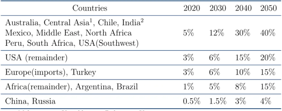
International Energy Agency (IEA) features some interesting statistics related to the predicted future growth of the CSP technology around the world [14]. As it can be seen in the Table 1.1, in some regions, 40% of the total electricity consumption will come from CSP plants by 2050.
Table 1.1: Electricity from CSP plants as shares of total electricity consumption.
Countries 2020 2030 2040 2050
Australia, Central Asia1, Chile, India2
Mexico, Middle East, North Africa 5% 12% 30% 40%
Peru, South Africa, USA(Southwest)
USA (remainder) 3% 6% 15% 20%
Europe(imports), Turkey 3% 6% 10% 15%
Africa(remainder), Argentina, Brazil 1% 5% 8% 15%
China, Russia 0.5% 1.5% 3% 4%
1: Afghanistan, Kazakhstan, Pakistan, Kyrgyzstan Tajikistan, Uzbekistan
2: Gujarat, Rajastan
The following figure, also taken from the CSP Roadmap, depicts the potential growth of CSP around the world till 2050, in terms of TWh per year.
Figure 1.3: Growth of CSP production by Region [14]
An important factor which can increase the achievable potential of CSP is the long range transportation of electricity. If an efficient way is found in order to transfer electricity from CSP plants to regions of low DNI, then much more people will have access to electricity from renewable sources. This would promote the transfer of large amounts of solar energy from desert areas to population centers. The DESERTEC Industry Initiative aims to establish a framework for investments to supply the Middle East, North Africa and Europe with solar and wind power. The long-term goal is to satisfy a substantial part of the energy needs of the Middle East and North Africa, and meet as much as 15% of Europe’s electricity demand by 2050 [14].
1.2
State of the Art
The technologies used in the CSP plants, basically differ on the way in which the sun irradiation is concentrated, by the focusing device, which is usually a series of mirrors, to the receiver, which contains the HTF to be heated up. A possible first level categorization can be made based on the focus type and the receiver type. The focus can be "line focus" or "point focus". The first means that the collectors track the sun along a single axis and focus irradiance on a linear/tubular receiver. In the latter, the collectors track the sun along two axes and focus irradiance at a single point receiver. This allows for higher temperature. As for the receiver, it can be "fixed", meaning that it is a stationary device that remains independent of the plant’s focusing device, or "mobile", where the receiver moves together with the focusing device. Mobile receivers are generally able to collect higher amounts of energy [14].
The CSP plants currently in use or designed, have the same three major compo-nents [8]:
1. The Solar Field, which includes the solar concentrators that reflect and focus the direct sunlight onto the relative small area of the receiver, through which the HTF passes. It includes mirrors, receivers, support structures, the HTF, collectors, heat exchangers, pumps and piping.
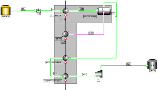
2. The Power Block, where the heat energy received by the HTF is converted into electricity, through conventional thermodynamic cycle, such as the Rankine or Brayton Cycle. Brayton cycle engines require higher working temperatures but they can provide higher efficiency. Rankine cycle engines have an important advantage over the Brayton cycle: the heat transfer coefficients in the generator are high, allowing the use of high-energy densities and smaller receivers [19]. The hot HTF exchanges energy with water (working fluid) in multiple heat exchangers, with the ultimate goal being to turn water into steam, through a boiler. In some cases, though, the same mixture/substance can be used as both HTF and working fluid. The steam which is then superheated, can be expanded through a turbine to produce mechanical power. An electric generator converts the mechanical power into electrical power. The Power Block usually consists of the turbine, the generator, a condenser, superheater(s), pump(s), a boiler and heat exchangers.
3. The Storage System, where the hot and cold storage fluid is stored in order for the plant to be able to function and produce energy even in cloudy days or during the night. The Storage media, tanks and heat exchangers constitute the Storage System. The following Figure 1.4 on the facing pageillustrates the three major components of a CSP plant mentioned above, all connected together:
1.2. State of the Art 9
Figure 1.4: A typical scheme of a CSP plant [20]
Before starting analyzing the main technologies used for power production in CSP plants, Table 1.2 on the next pageis presented that summarizes their main characteristics. Information was gathered from various different sources [7, 9, 12,
16, 19,21–23].
The state of the art technologies in the Solar Field of CSP plants are the following [9, 12,21, 24] :
1.2.1
Solar Power Tower
A Solar Power Tower (SPT) consists of an array of large flat tracking mirrors (heliostats), which are properly placed to avoid shadowing and reflect the direct beams of sunlight to a central receiver placed in an elevated support. The solar flux reaching the receiver can be as high as 1000kW/m2, providing and opportunity
to achieve really high working temperatures [25].
The mirrors are the major capital investment in a SPT plant [26]. They are computer-controlled and they move to maintain a focus from dawn to dusk. Figure1.5 on page 11presents a typical scheme of a SPT and a real life application of the Gemasolar SPT plant located in Sevilla, Spain. The specific plant has a capacity of 19.9MW and consists of an array of 2650 heliostats that aim solar radiation at a 140m height central tower. It can supply electricity to about 27,500 households in the south of Spain [27].
The central receiver usually contains water, which is heated up by the concen-trated solar radiation. Some of the hot steam produced can be stored, while most of it goes to the power block in order to be turned into high-pressure superheated steam, able to spin the turbine and produce electricity. The power block is located at the bottom of the tower. Usually for larger heliostats, Rankine cycle engines are installed. Brayton cycle engines are, also, a good alternative leading to higher efficiency, but they require higher operating temperature. [19].
T able 1.2: Represen tativ e features of the differen t CSP tec hno logies. P o w er T o w er Linear F resnel P a rab olic Dish P arab olic T rough Maturit y Medium Medium, pilot plan ts Lo w, demo plan ts High, commercialy pro v en Collector sun trac king T w o-axis Single-axis T w o-axis Single-axis Absorb er typ e P oin t T ubular P oin t T ubular Concen tration ratio 150-1500 10-60 100-1000 or >1000 w/ Stirli ng engine 10-85 Op erating temp erature ( o C) 250-650 250-390 800 290-550 Area requiremen t (m 2 /MWh) 8-12 6-8 30-40 4-6 Ann ual solar-to-electric efficiency 14-20% 9-13% 22 -25% 13-15 % Thermal efficiency 30-40% -30-40% 30-40% Plan t p eak efficiency 20-25% 20% 29% 14-21% Capital cost (US$/m 2 ) 476 234 -424 LCOE 1 without TES (US$/k Wh ) >0.29 >0.35 -0.26-0.30 1 LCOE: L evelize d Cost of Ele ctricity.
1.2. State of the Art 11
(a) (b)
Figure 1.5: (a) A typical scheme of a SPT (b) Gemasolar power plant in Spain [24]
Molten salt can be used, instead, as working fluid. In this case the molten salt is heated up by the solar radiation and it transfers heat to water though a heat exchanger, in order to produce steam. SPT technology is not "mature", yet. It is mainly applied to pilot plants, with some commercial projects under construction. To reduce the financial risk and to lower the cost of electricity production, often SPT plants are advised to hybridize with a natural gas combined-cycle [28]. One of the strong advantages of SPT is that it can reach high thermodynamic efficiency thanks to the high operating temperature. On the other hand, it requires large space area and relatively high installation costs. The largest plant using such technology was established in 2014 and it is located in the United States, named Ivanpah Solar Electric Generating System, with a turbine capacity of 392MW [29].
1.2.2
Linear Fresnel Reflector
A Linear Fresnel Reflector (LFR) CSP plant consists of linear mirror strips as reflectors, with receivers, tracking system, steam turbine and generator. Also in this case, the reflectors are the most important component of the system and they work the same way as the Fresnel lens. A Fresnel lens replaces the curved surface of a conventional optical lens with a series of concentric grooves. These contours act as individual refracting surfaces, bending parallel light rays to a common focal length. As a result, a Fresnel lens, while physically narrow in profile, is capable of focusing light similar to a conventional optical lens but has several advantages over its thicker counterpart [30].
In the Figure 1.6 on the next page the profile of a Fresnel lens is shown. Generally, using a Fresnel lens for light collection is ideal for concentrating light onto a photovoltaic (PV) cell or to heat a surface. The overall surface area of the lens determines the amount of collected light. The Figure 1.7 on the following page
plant located in Sicily, Italy.
Figure 1.6: Profile of a Fresnel lens [31]
(a) (b)
Figure 1.7: (a) A typical scheme of a LFR (b) LFR CSP power plant in Italy [32]
So, in the particular case of a LFR CSP plant, the sun’s rays are reflected by the big surface of Fresnel lens and focused at one point, generally on to a permanent receiver on a linear tower, shaped like a long cylinder that contains a number of tubes filled with water [33]. The idea for the power generation remains the same: the water evaporates to steam which is then superheated in order to spin a turbine and generate electricity. This technology is not commercially proven, it is still used mainly for demo purposes. In 2014 the largest operational LFR CSP plant was installed in India, with a capacity of 125MW.
LFR CSP technology offers a relatively low installation cost, a more stable design compared to the SPT but it is not able to reach high operating temperatures, due to its high thermal loss coefficient.
1.2.3
Parabolic Dish Collector
In the plants using the Parabolic Dish Collector (PDC) technology, a parabolic concentrator in the form of a dish is used to reflect solar radiation onto a receiver
1.2. State of the Art 13
(a) (b)
Figure 1.8: (a) A typical scheme of a PDC (b) Small PDC CSP plant in the USA [34]
at the focal point, above the dish. The concentrator is "point focus", meaning that it uses a two-axes tracking system to follow the movement of the sun. This makes the collector system really efficient, as it constantly tracks the sun.
The thermal energy can be either transported to a central generator for con-version or converted directly into electricity at a local generator coupled to the receiver. A dish-engine system, for example, is a stand-alone unit composed of a collector, a receiver and an engine. Its dish produces 5-25kW of electricity. The Strirling-engine systems are generally used instead of the traditional Rankine or Brayton cycle engines in this case. Microturbines and concentrating photovoltaics are being evaluated for future applications.[19].
PDCs are still only in demonstrative phase with a weak experimental feedback. But, the fact that they can achieve high operating temperature leading to high thermodynamic efficiency makes it a promising technology for CSP applications. Figure 1.8 presents a typical scheme of a PDC and a picture of one of the few commercial and operational PDC plants worldwide, in Utah, USA. The plant has a capacity of 1.5MW and consists of 429 solar dishes with a Stirling engine.
1.2.4
Parabolic Trough Collector
Parabolic Trough Collector (PTC) is the most common CSP technology, with a major data availability. PTCs are linear focus mobile collectors, with parabolic shaped concentrators. As it can be seen in Figure 1.9 on the following pagethe receiver is a black metal tube, covered with a glass tube to reduce heat losses and it is placed along the focal line of the receiver.
"Linear focus" indicates that a single-axis tracking system is used to follow the movement of the sun. The collector can be oriented in an east-west direction, tracking the sun from north to south or in a north-south direction, tracking the sun from east to west. The advantages of the former tracking mode is that little collector adjustment is required during the day and the full aperture always faces the sun at noon but the collector performance during the early and late hours of the day is greatly reduced, due to large incidence angles (cosine loss). North–south oriented troughs have their highest cosine loss at noon and the lowest in the mornings and evenings, when the sun is due east or due west. Over a period of one year, a
horizontal north–south trough field usually collects slightly more energy than a horizontal east–west one. However, the north–south field collects a lot of energy in summer and much less in winter. The east–west field collects more energy in winter than a north–south field and less in summer, providing a more constant annual output. Therefore, the choice of orientation usually depends on the application and whether more energy is needed during summer or winter [19].
Figure 1.9: A typical scheme of a PTC and its receiver [19]
In a Solar Field using PTCs, there are several hundred of troughs, placed in parallel rows. When the sun’s heat is reflected off the mirrors of the troughs, most of the heat is sent on to the tubular receiver. The receiver is filled with the HTF. which is heated up. It is, then, used to increase the temperature of water through a heat exchanger and produce steam. The produced steam enters a conventional steam turbine thermodynamic cycle to produce electricity. The used steam can be cooled, condensed and recycled again to repeat the process. And the same goes for the HTF: after being used in the thermodynamic cycle, it is recycled back to the solar field to increase its temperature and repeat the cycle.[14]. It is common that a natural gas system hybridizes the PTC CSP plants and contributes to 25% of their output.
The most expensive project so far undertaken based on this technology was the Solana Generating Station, installed in 2013 with a cost of approximately 2billion US$. The planned electricity generation is estimated at 944,000MWh/year (capacity of 107.7MW). [35]. While, one of the biggest applications of this type of system is the nine southern California power plants known as solar electric generating systems (SEGS), which have a total capacity of 354MW [36]. A picture of SEGS is shown in the following figure.
This is the most mature, proven and widely-used CPS technology, with several plants operating and being constructed all around the world. Of course, there is still research and development aiming to further reduce the cost in the following years. Some of the main goals are [19]:
• Higher-reflectivity mirrors.
• More sophisticated sun tracking systems.
• Better receiver selective coatings, with higher absorption and lower emittance. • Better heat transfer techniques.
1.2. State of the Art 15
PTC technology offers a large experimental feedback and a relatively low installation cost. It, also, produces the lowest cost solar-generated electricity, compared to the other existing technologies. On the other hand, parabolic trough plants require a considerable amount of land and large amounts of water. Water availability can be a serious issue in the dry regions where these plants are usually situated.
1.3
Thermal Energy Storage
The biggest disadvantage of using Solar Energy to produce electricity is its intermittent behavior. The solar radiation reaching a CSP plant, for example, is not constant every day, it even changes within a single day. This happens due to weather conditions and due to the direction and intensity of the sun seasonally. Households and businesses need a constant power supply and their everyday activities strongly depend on this fact. So, when a CSP plant provides electricity to them, variability of the power output is not an option.
There are two main solutions to overcome intermittency in a CSP plant [9]: 1. Use a Fuel Backup System (FBS) that burns fossil fuel or biomass
2. Use a Thermal Energy Storage (TES) system
In both cases the idea is to dispatch heat during periods of weak or no solar irradiation (during the night), in order to maintain stable the power output of the plant. The option of the hybridization with a FBS manages to increase the plant’s global efficiency [38], but it produces pollutants from combustion and it is, also, expensive as it requires feeding of a fuel.
TES on the other hand, is an integrated part of a CSP plant, consisting of tank(s) that act as reservoir of energy that collect thermal concentrated energy during the normal operation of the plant and dispatch it to the power block whenever is needed. It is a less pollutant solution, with lower capital costs but higher LCOE [16].
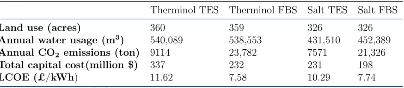
In 2015, an interesting paper was published by T.E. Boukelia et al. [39], in which a 4E(energy-exergy-environmental-economic) comparative study was performed in 8 different configurations of PTC solar thermal power plants, with two different HTFs, with or without FBS or/and TES present. A constant net power of 50MWe was generated by all the configurations. The same TES capacity and solar field layout was considered in every case. Focusing on the four configurations using molten salt or Therminol VP-1 as HTF, the two with TES only and the other two with FBS only, the following results* were obtained, related to the environmental and economic aspect:
Table 1.3: Comparison between TES and FBS for different PTC plant configurations.
Therminol TES Therminol FBS Salt TES Salt FBS
Land use (acres) 360 359 326 326
Annual water usage (m3) 540,089 538,553 431,510 452,389
Annual CO2 emissions (ton) 9114 23,782 7571 21,326
Total capital cost(million $) 337 232 231 198
LCOE (£/kWh) 11.62 7.58 10.29 7.74
*Table adjusted from [39]
It can be observed that there is not a big difference neither at the land occupied nor at the annual water usage between the two technologies of TES and FBS. The
1.3. Thermal Energy Storage 17
strong disadvantage of the FBS is evident in the numbers: the annual emissions of carbon dioxide are greatly higher compared to the emissions of the TES. As it was mentioned earlier though, the total capital cost as well as the LCOE are lower for the case of FBS.
Another interesting fact is that more than 70% of the CSP plant currently under construction and almost 80% of those already planned, will be integrated with a TES system [9], as it can be seen in the following fFgure 1.11.
Figure 1.11: Percentage of TES systems in CSP plants [9]
There is, also, the option of combining a TES and a FBS in a single plant, thus achieving a tradeoff between total capital cost, efficiency and LCOE. Indeed, as shown in the paper of T.E. Boukelia et al. [39], a configuration consisting of both TES and FBS, achieves the lowest LCOE, a lower capital cost than the FBS alone but the highest CO2 emissions compared to the values of the other configurations
of the Table 1.3 on the facing page. A simplified scheme of an oil plant with integrated both systems is shown in Figure1.12.
Focusing on the TES technology, it may offer the following functions [16, 21,
40]:
• Mitigating short fluctuations during transient weather conditions. Without TES, solar power is an intermittent power source, dependent on when the sun shines. The ability to store energy and dispatch solar power when is needed helps to make solar power plants a more reliable and firm power source. • Shifting the power generation period from peak hours of solar irradiation
to peak hours of demand, solving in this way, the time mismatch between solar energy supply and electricity peak demand. In some cases, utilities have greater need for power at night. Without TES, it is impossible for a CSP plant to deliver electricity during the night, when it is needed the most. It should, also, be considered that the power produced during the peak hours is usually valued higher than during the periods of low demand. This provides an economic benefit for the addition of a TES system, that extends the generation period even during the night.
• Reducing the number of start-ups of the plant. Starting up a power plant takes time, energy, causes additional corrosion on equipment, and is often the time when systems are most susceptible to failure. Solar power plants without thermal storage, during partially cloudy days, are forced to start-up every time sufficient solar energy is available. Multiple plant start-ups in a single day are not unusual. The addition of thermal storage allows solar energy to be collected during short sunny periods and stored for later use when sufficient energy has been collected to run the power plant for a sustained period. • Improving the annual capacity factor. This is a performance parameter that
compares the net electricity delivered by the plant to the energy that it could have produced under continuous full power operation during the same time period. A 7hr of storage, for example, can increase this factor from its typical value of 25% to 28% and up to 43%.
• Increasing the plant availability. A TES system provides a buffer in case of any delays caused by long start-up, faulty equipment etc. In a plant without TES, even minor delays can result in a significant loss of power generation. Before implementing a TES in a CSP plant, there are some considerations that have to be taken into account. Firstly, the space availability has to be evaluated. This is essential for choosing the type of TES. Also, the operating T as well as the maximum load should be thought of. Another important point is to access how the increased capital costs of the TES will affect the LCOE based, always, on the available tariffs.
When the time of implementation comes, there are some important design criteria for the TES that should not be ignored. They are summed up in the Table 1.4 on the facing page [41, 42].
1.3. Thermal Energy Storage 19
Table 1.4: Design criteria for a TES of a CSP plant.
Design Criteria Influencing factors
Technical 1. High energy thermal storage capacity
2. Efficient heat transfer rate between HTF and storage material 3. Good mechanical and chemical stability
4. Compatibility between HTF, heat exchanger (if present) and storage material
5. Complete reversibility for a large number of cycles 6. Low thermal losses
7. Ease of control
Cost-effectiveness 1. Cost of TES materials
2. Cost of heat exchanger (if present) 3. Cost of the land for the TES
Environmental 1. Operation strategy
2. Integration of the TES in the plant 3. Environmentally friendly materials
There are generally three different ways in which thermal energy can be stored: sensible, latent and thermochemical heat storage.
Sensible heat storage means that thermal energy is stored/released by rais-ing/decreasing the temperature of a storage material, in a pure physical process without any phase change. It is the most commonly used and most mature TES technology with many inexpensive materials available [16, 21, 42]. In the case of water for example, sensible is the heat required to increase its the temperature in constant pressure without changing its phase. The sensible heat storage depends strongly on the characteristics of the storage material. Its specific heat cp,
deter-mines the energy density and the thermal diffusivity k/cp, determines the rate at
which that heat can be released or extracted. The amount of energy stored in this case is:
Qst = msmcp∆T (1.1)
msm: the mass of the storage medium
Density and specific heat of the storage material, operating T, thermal conductivity, diffusivity, chemical/thermo-chemical stability and cost of materials should be taken into account [43].
In the latent heat storage, thermal energy is stored/released by a material while changing its phase at a constant temperature. It is a pure physical process without any chemical reaction. In the example of water, latent heat is the heat needed to change its phase in constant temperature and pressure. Mainly solid-liquid transition is preferred and the substances used under this technology are called Phase Change Materials (PCM). PCM allow large amounts of energy to be stored
in relatively small volumes, resulting in some of the lowest storage media costs of any storage concept [42]. Latent heat storage can offer higher energy density but a poor heat transfer performance due to the very low thermal conductivity of the PCM. The heat stored in the case of a solid to liquid phase change:
Qst = msm[cps(Tm− Ts) + h + cpl(Tl− Tm)] (1.2)
where h is the enthalpy of phase change, Tm is the melting temperature, Ts: the
starting temperature of the solid and Tl: the final temperature of the liquid.
It is a nearly isothermal process that can provide significantly enhanced storage quantities when compared to sensible heat storage. Isothermal storage is an im-portant characteristic because solar field inlet and outlet T are limited due to constraints in the HTF, solar field equipment and steam turbine cycle [21].
The least investigated technology so far is the thermochemical storage. It is based on reversible chemical reactions which are characterized by a change in the molecular configuration of the reactants. Solar heat is used to drive an endothermic chemical reaction and then stored in the form of chemical potential. During the discharge, the stored heat can be released by the reversed exothermic reaction, sometimes by adding a catalyst [44].
It has been receiving the attention of the scientific community because it can potentially store more energy than sensible or latent heat systems thanks to the heat of reaction. The heat stored:
Qst = αm∆H (1.3)
where α is the fraction of the components that reacted and ∆H is the heat of reaction per unit of mass.
The thermochemical heat storage offers the highest energy density (up to 19 times greater than the latent heat) and constant temperature. The dissociation reaction can be stored indefinitely at ambient temperature, thus reducing the thermal losses. On the other hand the design of the reactors can be complex and the cost high. Also, the chemical stability is still low. The performance of the system is degraded over charge and discharge and it is strongly restricted by the reaction kinetics [21,44]. In the particular case of the CSP plants, the TES systems can be further classi-fied as active and passive. In the active storage systems, the storage medium (fluid) itself flows to absorb or release heat by forced convection . The passive storage systems are generally dual medium storage systems: the HTF passes through the storage only for charging and discharging a solid material, carrying the energy received from the energy source (solar field). In other words, the HTF circulates through the TES system in order to heat up or cool down the (solid) storage materials that are kept inside [9, 21, 43]. Another conceptual design for TES is the combined system. It is a three-part storage system where a phase change material is deployed for two-phase evaporation in a Direct Stem Generation (DSG) plant, while concrete storage is used for storing sensible heat, i.e., for preheating of water and superheating of steam. A system like this will be used in the 1 MW Dahan DSG power tower plant in China. The low temperature stage consists of a
1.3. Thermal Energy Storage 21
steam accumulator that will store saturated steam at 2.35 MPa, 220.7 oC. During discharging, the saturated steam will be converted to superheated steam via a storage system which uses oil as the storage medium [21].
Another way to diversify the type of TES in CSP plants is based on the number of storage tanks used.
1.3.1
Two-tank Storage
It has been successfully commercialized in the solar field with many applications in the CSP plants. It uses two tanks to store the storage medium: the "hot tank" where the storage medium with increased temperature is stored and the "cold tank" which contains the storage medium of low temperature.
Direct Storage
In the case of the direct two-tank storage, the energy storage mechanism is placed on the main process streams and it is directly fed by energy, without any utility/process/heat exchanger. The energy storage linearly increases/decreases according to the inflow and outflow of the tanks [45]. An example of a simplified scheme for a CSP plant working with a two-tank TES is presented in Figure 1.13.
Figure 1.13: The two-tank direct TES [46]
The working principle of the system above is the following. At the startup of the plant the HTF is loaded in the cold tank at a low temperature. During the day, when the sun provides enough radiation, the cold HTF is pumped out of the cold tank and into the solar field (here: solar collectors). There, the temperature of the HTF rises. Some of the hot HTF is now sent for storage at the hot tank while another part passes to the heat exchanger train at the power block in order to produce electricity. This procedure goes on till the sunset, when the radiation of the sun is not anymore enough to heat up the cold HTF at the solar field. At that point the level inside the hot tank has reached a certain predicted value. During the night, the hot HTF is pumped out of the hot tank and enters the power block to continue producing electricity. It is cooled down because it passes from a series of heat exchangers and then, at a low temperature it enters the cold tank. The solar field is not active. When the next day comes, the cold tank has been filled up with cold HTF and the hot tank is either empty or has a low level of hot HTF.
1.3. Thermal Energy Storage 23
The process is repeated all over again.
In the direct TES configuration, the HTF acts as both the transfer fluid and the storage medium. The liquid holdup for the hot and cold tank have linear behavior during the day. During the charging period, the content of hot tank gradually increases and conversely through the discharging period, the harvested energy is consumed and consequently the levels of the stored liquid decreases with a similar slop of the harvesting one [47]. This behavior is depicted in the following figure.
Figure 1.14: Dynamic behavior of the level of the tanks in the two-tank direct storage [47]
It can be observed that at night and early in the morning, the level of the hot tank decreases linearly. The hot HTF is flowing out of the hot tank in order for the plant to be able to produce constant power output. During the day, at the charging period, the cold HTF is flowing through the solar field and into the hot tank, thus the level of the former is decreasing and the level of the latter is increasing. The sum of the two levels of the tank remains constant throughout the 24h (dotted horizontal line). For each tank, at any point of operation, the accumulation is practically always non zero:
dm
dt = ˙min− ˙mout (1.4)
Where ˙m is the mass flow rate. Indirect Storage
The indirect two-tank storage is the most installed TES technology in the PTC CSP plants [48]. In this technology the storage medium from the cold storage tank is heated up in a heat exchanger by a HTF coming from the solar field. Then the heated storage medium is stored in the hot tank. In contrast to the direct two-tank storage, the storage medium is different from the transfer fluid. This is sometimes
inevitable because the circulating HTF is maybe too expensive or it does not have the suitable properties in order to act as a storage medium. The most important addition and the most vital part of this configuration is the heat exchanger, where the HTF and the storage medium exchange energy. The scheme of a two-tank indirect TES system is presented in the Figure 1.15.
Figure 1.15: The two-tank indirect TES [49]
At the charging phase, HTF is pumped from the cold tank and it is heated as it passes through the heat exchanger (here inside the blue line) and flows into the hot tank. To discharge the storage system, storage fluid is pumped from the hot tank and transfers its heat through the heat exchanger to the HTF, and return to the cold tank. The hot HTF, from the output of the heat exchanger goes towards the power block for power generation.
The main advantages and disadvantages of the two-tank storage are reviewed in the Table 1.5.
Table 1.5: Review of the two-tank TES.
Advantages 1. Low risk approach,
cold and hot storage medium are stored separately 2. Possibility to raise the solar field output temperature,
rankine cycle efficiency of the power block can reach 40% Disadvantages 1. High cost of material used as HTF and storage materials
2. High cost of extra heat exchanger (if present) and 2nd tank 3. High risk of solidification of storage fluid
1.3. Thermal Energy Storage 25
1.3.2
Single-tank Storage
In the single-tank or thermocline storage, one tank only contains simultane-ously hot and cold HTF in stratified way by appropriately feeding them to it from the top to the bottom. This technology requires that the lower density hot fluid rests stably above the higher density cold fluid and remain essentially stratified during energy charge, resting and discharge [50]. Hot fluid is pumped into the single tank, gradually displacing the colder fluid. A thermal gradient is created within the system and it is ideally stabilized and preserved by buoyancy effects, which induce stratification leading to two isothermal regions along the vertical direction. In other words, this gradient is a narrow layer of substantial temperature gradient that grows at the interface between the hot and cold region and it is known as thermocline or heat transfer region [51]. In order to achieve a high efficiency, the temperature stratification must be maintained constant and mixing should be avoided. Usually a filler material (quartzite rock, sand, concrete, industrial waste) is added in the thermocline to enhance the thermocline effect and to reduce the needed quantity of storage materials. It aids in maintaining the gradient and reduces natural convection within the liquid. Systems using filler materials are categorized as passive because the filler acts as the primary storage material [21,
52, 53].
In the following figure, a typical scheme of a CSP plant using direct single-tank storage is presented.
Figure 1.16: The single-tank (thermocline) TES [46]
The hot fluid is loaded into the tank from the top at daytime and at the same time the cold fluid is pumped out from the bottom into the solar field to harvest solar energy. During the night, the cold fluid line is off and no hot fluid is supplied to the thermocline. On the other hand, the hot fluid is continuously pumped out from the top and releases the stored heat to the plant (e.g to produce electricity) before returning back to the bottom. This process moves the thermocline region downward
daytime and increases the thermal energy potential in the storage. During this charging phase (hot HTF going in and cold HTF going out of the thermocline), the temperature of the cold HTF entering the heat exchanger is constant until the gradient reaches the bottom of the tank. At that point the temperature coming out of the bottom of the tank starts to rise, as it can be seen at the following figure:
Figure 1.17: Dynamic behavior of the temperature of inlet and outlet stream of a thermocline during charging phase [53]
At night, reversing the flow, moves the thermocline upward and depletes the thermal energy [46, 50].
Similar behavior is observed for the temperatures of the inlet and outlet streams.
Figure 1.18: Dynamic behavior of the temperature of inlet and outlet stream of a thermocline during discharging phase [53]
In thermocline systems, the exergetic efficiency depends on the ability to keep the thermocline region as narrow as possible, thereby achieving the best possible temperature separation [54]. So, an ideal thermocline tank is a conceptual tank consisting of hot and cold fluid separated by a fictitious barrier without any filler
1.3. Thermal Energy Storage 27
material (ε = 1). In this way, in an ideal thermocline there is no loss in exergy during charging and discharging process.
The temperature of the filler material is always higher than the fluid within the tank since the filler material acts like a heat reservoir. As the operation time of tank increases, filler material eventually loses heat to the flowing cold fluid and attains thermal equilibrium with cold fluid after a specific operation time of tank. The operation time of tank is decided based on the outlet temperature of tank which is a function of time. In a study published by KS Reddy et al it was observed that as the operation time increases, thermocline thickness in the tank increases in the upward direction and eventually gets vanished [51]. This is depicted clearly in the Figure1.19, where results of simulations for the temperature distribution inside a single tank, for three different HTFs, are shown.
Figure 1.19: Temperature distribution of different HTFs in a single-tank storage [51]
Thermocline storage is designed in such a way that the velocity of the fluid is adjusted to maintain the thermocline thickness within the tank for the required operation of the tank. In reality though, as shown in Figure1.19, the thermocline thickness increases with operation time of the tank because of the convective mixing happening between the hot and the cold fluid, which is to be retarded. The influence of the fluid properties like viscosity, thermal conductivity is responsible for maintaining thermocline thickness within the tank for the required operation of the tank.
In a paper published by Pacheco et al. [53], a comparison between different possible filler materials for single-tank storage was carried out. The ideal filler material would be inexpensive and widely available, with a high heat capacity, a low void fraction, compatible with nitrate salts and nlion-hazardous. The most successful candidates were quartzite, taconite, marble, NM limestone, apatite, corrundum, scheelite, and cassiterite. Because taconite, marble, NM limestone, and quartzite are available in bulk quantities for a reasonable price, the attention was focused on these materials to conduct thermal cycling tests. Quartzite rock and silica and turned out to have the best performance.
its dimensions have to be calculated correctly to guarantee the correct overall performance of the plant. Generally, because of the height required for the gradient, taller tanks with smaller diameters are favored over shorter tanks with larger diameters. It is interesting to see how the sizing of an ideal storage tank can be approached [50].
The heat storage or delivery rate for any storage tank is related to the required mass flow rate and the required period of operation of a thermal power plant. If the storage system is ideal, the heat delivery rate will be:
˙
QT = ˙m ¯C(TH − TL) (1.5)
where TH is the temperature of the hot fluid stored and TL: the temperature
that the fluid reaches after it gives out its thermal energy. The ideal total energy delivered for a specific time span tref :
QT = trefQ˙T (1.6)
and the ideal volume of the fluid storage tank: Videal =
trefm˙
ρf
(1.7) In reality, the tank dimensions are decided based on various values of operational parameters taken directly from the power plant. The electrical power, the thermal efficiency, the period of operation, the inlet/outlet fluid temperature, the properties of the HTF and the thermal storage material including the fillers should all be taken into consideration [50, 54]. Computational Fluid Dynamics (CFD) is strongly involved in the decision.
The reasons why thermocline should be investigated more for the CSP plants, but also some of the drawbacks of this technology are listed in the Table1.6 [16,43, 46,
47,52].
Table 1.6: Review of the single-tank (thermocline) TES.
Advantages 1. Ability to dispatch thermal energy at nearly constant temperature over most of the discharge cycle
2. Possibility to reduce 33% of the cost of TES Disadvantages 1. Requires really good control to avoid mixing
2. The design of the storage system is more complex 3. Stability of the filler material in the hot HTF 4. Thermo-mechanically induced ratcheting*
*In mechanics, ratcheting is a behavior in which plastic deformation accumulates due to cyclic mechanical or thermal stress. Thermal ratcheting of the tank: as the tank heats up, its internal volume increases and the fill particles settle lower to cover the additional volume created. When it cools down, it compresses, but the particles cannot physically move upwards due to gravity build-up of mechanical stress in the tank shell through repeated operational cycles.
1.4. Heat Transfer Fluid 29
1.4
Heat Transfer Fluid
Water has been the most popular HTF for most of the industrial applications thanks to its availability, high specific heat, high density and moderate viscosity [10]. The biggest drawback is the limited range of temperatures in which water can be used. In order to keep it liquid above the 100oC, high pressure is needed and high pressure equals really high costs. This is the reason why water is not generally used as HTF in the CSP plants, where high temperatures are reached, in order to create the biggest heat exchange "reservoir" possible for the HTF. There are some specific characteristics that a HTF should have in order to be suitable for use in the CSP field taking into account that the HTF is the "bond" between solar field, power block and storage system (if present). These characteristics are [13, 51, 55,
56]:
• Extended working temperature range. • Good thermo-physical properties. • Anti-hazard.
• High heat capacity.
• Moderate density and viscosity. • High thermal energy storage density. • Low corrosion with metal alloys. • Low cost.
All of the characteristics listed above have to be combined, in order to satisfy the goal of increasing the efficiency of the cycle, reducing the costs and making the components of the process robust and compatible with each other.
The HTFs currently used in the CSP plants, can be categorized based on their chemical composition. The main ones will be analyzed and some innovations made in the area of the HTFs will, also, be presented.
1.4.1
Thermal Oil
Mineral, silicon and synthetic oil have been tested and used in CSP applications [13]. They can maintain their liquid phase up to 300oC and they are thermally stable
up to 400oC. That is why they are not suitable for high-temperature applications in
the solar field. This temperature limit is a serious barrier to increasing the power block efficiency of a CSP plant, because the temperature of the steam delivered cannot be higher than 390oC, thus limiting the steam turbine efficiency [55]. The
three thermal oils mentioned above, have more or less the same (relatively low) thermal conductivity of 0.10-0.12W/mK and low density of 770-900kg/m3. This
causes limitations to the rate at which the heat can be released and extracted. Oils have rather high vapor pressure which causes serious safety and environmental issues. Another problem with these thermal oils is that they are expensive [41].
Probably the most well known thermal oil in the CSP industry is the Therminol VP-1. It is an organic thermal oil that consists of biphenyl (C12H10) and diphenyl
oxide (C12H10O) pair. This is an eutectic mixture of two very stable organic
compounds. Therminol VP-1 is produced by Eastman Chemical Company but the same eutectic mixture is used, also, in a HTF developed by Dow Chemicals, under the name of Dowtherm A. Therminol VP-1 can be used in a wide temperature range, thanks to its low crystallization point of 12oC. It has some interesting properties as it can be used both as vapor and liquid-phase HTF. The liquid phase heating does not require any condensate return equipment and it can be managed by simpler and more easily operated systems. Vapor phase heating, on the other hand, can provide much more heat per unit mass of heat medium and it can offer an easier temperature control to the user because of the more uniform distribution of temperature. Therminol VP-1 can be used at up to 400oC with a normal boiling point of 257oC. Overheating must be avoided because it has an
autoignition temperature of 601oC. It has the strong advantage of high thermal stability [57].
1.4.2
Molten Salt
In order to help the CSP plant achieve higher efficiency in the power block, a HTF that works at higher temperatures compared to the thermal oils, have to be used. Molten salts have become a really could candidate exactly for this reason. They are thermally stable at high temperatures, up to 600oC [13, 43]. At high temperature, they have low vapor pressure, similar to that of the water [58]. Another important advantage of molten salts is that they are suitable for TES, offering an efficient heat storage and this is why the two-tank indirect TES with molten salts is the most widely used TES configuration in CSP plants. [48, 59]. Another interesting conclusion, reported by D. Kearney et al., is that the use of molten salts as HTF makes economical sense only if the plant is includes a TES system [60]. It should, also, be mentioned that the risk of fire or pollution is low when molten salts are being used, as they are non-flammable and non-toxic. Of course, the disadvantages are not absent. The higher outlet temperature of molten salts means heat losses from the solar heat, requiring more expensive piping and materials [43]. Also, their high melting point of around 220oC introduces the risk
of crystallization inside the pipes during winter or night-time. A routine freeze protection operation should be carried out. During this operation, the HTF is circulated at a low flow rate through the SF during the night as required. By this means, the piping will be kept warm, thus avoiding critical thermal gradients during start up. If the HTF temperature falls below a certain value, then an auxiliary heater is used to maintain a minimum temperature [61]. A significant amount of energy is consumed during this procedure.
The main strong points and drawbacks of molten salts compared to thermal oil are highlighted in the following table [55, 61]:
An example of a molten salt HTF is the Hitec XL. It is a ternary mixture of sodium, potassium and calcium nitrates: N aN O3(7wt%) − KN O3(45wt%) −
1.4. Heat Transfer Fluid 31
Table 1.7: Molten Salt as HTF: comparison with Thermal Oil.
Advantages over thermal oil Disadvantages over thermal oil 1. Efficient heat storage 1. Thermal losses overnight 2. Higher working temperature 2. Complex solar field design 3. No pollution/fire-hazard 3. Higher electricity consumption
4. Lower mass flow leads to high ∆P
the molten salts and this is its strong advantage. However, it is thermally stable only up to 500oC [13]. Many HTFs consisting of almost the same components but in different molar fractions exist: Hitec, LiNaK carbonate, Sandia Mix and Halotechnics SS-500 are some examples. Solar Salt is the most popular HTF used in CSP plants. It is a binary salt mixture of 60wt% NaNO3 (sodium nitrate)
and 40wt% KNO3 (potassium nitrate). It melts at 223oC and remains thermally
stable at liquid phase up to 600oC. Many reviews can be found in literature for this
specific HTF, that assess its performance within the plant as well as the possible corrosion effects. It is one of the most well-studied HTFs and this is a reason why it is generally preferred in the CSP plants.
A recent paper published by A. Bonk et al. [62], compares five different molten salt systems: Solar Salt, HitecXL, LiNaK Nitrate, Hitec and CaLiNaK/NO23. Their physical properties are discussed and useful temperature-dependent data are provided. In the Table 1.8 on page 33 some of the most important thermal and physical properties of the most commonly used HTFs in the CSP plants are summed up [13,43, 61].
1.4.3
Innovative materials
The search by the scientific community for even more efficient HTFs, suitable for CSP applications, still continues. A lot of papers have been published during the recent years, proposing new ideas for alternative HTFs that seem promising and could bring a revolution in the CSP field in the near future. G. Flamant et al. [56] and J. Spelling et al. [63], proposed a dense suspension of particles (solid fraction in the range of 30%-40%) in vertical adsorbing tubes submitted to concentrated solar energy. Temperatures up to 750oC are expected, thus opening new opportunities for
high temperature applications and for thermodynamic cycles with higher efficiency. A study carried out by A. d’Entremont et al. [64] proposes the high temperature magnesium iron (M g2F EH6) hydride coupled with the low temperature sodium
alanate (N a3AlH6) hydride as a possible HTF for CSP plants. The system’s
operating temperature in this case varies from 450oC to 500oC, with hydrogen pressures between 30 bar and 70 bar. This makes the TES system a suitable candidate for pairing with a solar driven steam power plant. The model results obtained, showed an actual TES system volumetric energy density of about 132 KWh/m3, which is more than 5 times higher than the U.S. Department of Energy
SunShot target (25KWh/m3).
Many papers in 2018, investigated the possibility of the use of nano-fluids in solar concentrating technologies. The term "nano-fluid" refers to a fluid which is
created by dispersing nanoparticles into a base fluid. The used nanoparticles can be metallic (Al, Fe, Cu, Ag, Au) or non-metallic (Al2O3, F e2O3, ZnO, CuO, SiO2,
T iO2). Carbon nanotubes are, also, common. The nanoparticles are extremely
small with a diameter as low as 10nm. The base fluids can be water, ethylene glycol or thermal oils. The nano-fluids have increased thermal conductivity, dynamic viscosity, density and decreased specific heat capacity compared to the base fluids. This allows them to carry higher amounts of thermal energy and offer higher thermal efficiency to the collectors. The biggest limitation that has to be taken into consideration is that the nano-fluids may increase the pressure drops. A comprehensive and complete review of this relatively new technology is given by E. Bellos et al. [65], focusing on the performance of the nano-fluids in different collector types. A. Yasinskiy et al. [66] analyzed the properties of T iO2-based nano-fluids
with a diphenyl oxide-biphenyl mixture as the base fluid and 1-octadecanethiol (ODT). They observed an improvement in the thermal properties and the efficiency.
Pt-based nano-fluids with ODT were, also, tested by R. Villarejo et al. [67], showing enhanced thermophysical properties such as increased thermal conductivity and heat transfer coefficient.
There is still a long road to be covered in order for these concept ideas to reach the market. In any case, it is really encouraging that serious efforts are being made towards the improvement of the current methods used in CSP plants. It is evident, that the CSP technology has gained the trust of the scientific community and it is ready to move to new frontiers.
![Figure 1.2: Purpose of CSP plants and their respective percentage [9]](https://thumb-eu.123doks.com/thumbv2/123dokorg/7510859.105194/20.892.155.760.599.767/figure-purpose-csp-plants-respective-percentage.webp)
![Figure 1.10: Photograph of SEGS: a PTC CSP plant in the USA [37]](https://thumb-eu.123doks.com/thumbv2/123dokorg/7510859.105194/29.892.184.688.231.567/figure-photograph-segs-ptc-csp-plant-usa.webp)
![Figure 1.12: Scheme of an oil plant with integrated TES and FBS [39]](https://thumb-eu.123doks.com/thumbv2/123dokorg/7510859.105194/31.892.174.713.878.1065/figure-scheme-oil-plant-integrated-tes-fbs.webp)
![Figure 1.14: Dynamic behavior of the level of the tanks in the two-tank direct storage [47]](https://thumb-eu.123doks.com/thumbv2/123dokorg/7510859.105194/37.892.182.707.293.611/figure-dynamic-behavior-level-tanks-tank-direct-storage.webp)
![Figure 1.18: Dynamic behavior of the temperature of inlet and outlet stream of a thermocline during discharging phase [53]](https://thumb-eu.123doks.com/thumbv2/123dokorg/7510859.105194/40.892.249.666.668.927/figure-dynamic-behavior-temperature-outlet-stream-thermocline-discharging.webp)
![Figure 1.19: Temperature distribution of different HTFs in a single-tank storage [51]](https://thumb-eu.123doks.com/thumbv2/123dokorg/7510859.105194/41.892.129.744.387.671/figure-temperature-distribution-different-htfs-single-tank-storage.webp)