Politecnico di Milano
Scuola di Ingegneria Industriale e dell’informazione
Corso di Laurea Magistrale in Ingegneria Energetica
Alternative salt based secondary fluids for indirect
refrigeration systems
Advisor: prof. Luca Molinaroli
Co-advisor: dr. Monika Ignatowicz
Tesi di Laurea Magistrale di
Lorenzo Barcarolo matr. 858346
A
CKNOWLEDGEMENTSFirst of all, I would like to thank my supervisor, Monika Ignatowicz, at the division of Applied Thermodynamic and Refrigeration at KTH Royal Institute of Technology for helping me with professionality and patience. Her door was always open for any question or doubt.
Furthermore, I would like to express my sincere gratitude to my advisor, Luca Molinaroli, at the division of Energy at Politecnico di Milano for the help and support he gave me through the writing of this thesis.
Special thanks go to all the friends I made during those university years. You truly made them worth the effort.
Finally, I must express my very profound gratitude to my parents, my sibling and my familiars for providing me with unfailing support and continuous encouragement throughout my years of study. This accomplishment would not have been possible without them. Thank you.
E
XTENDED ABSTRACTIntroduction
One of the nowadays biggest challenges is global warming alleviation. Since the 1987 Montreal Protocol, international authorities have recognized harmful effects of greenhouse gases to the planet and showed willing to collaborate by gradually banning all gases with Ozone Depletion Potential (ODP). The treaties where further developed by 1997 Kyoto Protocol by decreasing emissions of high Global Warming Potential (GWP) greenhouse gases which contribute to global warming and climate change. More recent international treaties such has European regulation No. 517/2014, better known as F-Gas regulation, and the 2015 Paris Agreement have recently renewed and further limited the legislation dealing with high GWP gases scheduling and regulating their phasing out.
Refrigeration sector has a huge role in this context, accounting for 17 % of the world electricity consumption (Coulomb and Dupont, 2015) and 10 % of the global CO2emissions
(Maidment, 2014), with a total number of refrigeration, air-conditioning and heat pump systems in operation worldwide of roughly 3 billion, including 1.5 billion of domestic refrigerators (Liu et al., 2017). Those numbers are expected to increase in the years to come, due to global warming, population growth and developing countries economy growth. Furthermore, refrigeration systems CO2 emissions are both direct and indirect. Direct
emissions are those related to leakage of the primary refrigerant into the atmosphere, they account roughly for 20 % of the whole emissions. Indirect emissions are those related to production, transportation of the primary refrigerant and electricity related ones to run the refrigeration system during its whole life cycle, they roughly account for 80 % of the whole emissions (Coulomb and Dupont, 2015). Direct emissions can be reduced by using primary refrigerants with low GWP, by imitating leakages with better regulation and maintenance of the systems and by reducing the primary refrigerant charge. Reducing indirect emissions is more complex since they depend on various factors, an important one is the country energy mix.
The aim of the previously described international treaties is to keep the global temperature increment well below 2 °C. Thus, this thesis objective is to contribute at the achievement of this important goal studying new secondary fluids to decrease CO2 emissions of the
refrigeration sector. This can support the cause in two ways. First, the use of a secondary fluid, and therefore an indirect refrigeration system, reduces the refrigerant charge up to 60%. This has a huge impact on leakage risks. Furthermore, allows to confine the primary refrigerant loop in a machine room, making also possible to used more efficient, low GWP refrigerants such as ammonia and propane, even though they are flammable or toxic. Second, using indirect refrigeration also increases the COP up to 10 % (Lee et al., 2015), increasing
One of the best secondary fluids is water, for its availability, non-toxicity, non-flammability, environmentally friendly behaviour, cheap price and high heat transfer performances. However, often in refrigeration systems, secondary fluid temperatures go below 0 °C, in this case water would become solid and it would break the system. Therefore, the need to maintain the secondary fluid in its liquid phase arises. The most common solution is to use water and propylene glycol mixtures. However, this secondary fluid does not have excellent heat transfer properties; it is produced from fossil oil reservoir and is harmful ground in the case of leakage.
This thesis proposes salt based secondary fluids as a new alternative to alcohol and glycol based ones. It studies some formate and acetate salts for the first time, since no data is published in the scientific literature. Solutions of water and cesium formate, cesium acetate, ammonium formate, ammonium acetate, potassium formate, sodium formate were studied. Moreover, lithium formate and lithium acetate were also included in the first place, but measurements have not been completed due to solution stability problems.
Methodology
The approach of the study was to measure the main thermophysical properties of the selected secondary fluids through cutting edge lab equipment. The first part of the activity focused on literature reviews and the study of state of the art technologies and secondary fluids; then the experiments were run, and results were collected and, finally, in the last part of the activity data analysis was carried out. The following properties were measured: freezing point temperature, refractive index, density, viscosity, specific heat capacity and thermal conductivity. For each property one or two different instruments were used, and measurements were reiterated the necessary amount of times to assure repeatability and quality.
Another important aspect to consider is the corrosion character of the secondary fluid; during system design, the system parts have a high impact on the lifetime cost of the refrigeration system. Indeed, it is not useful to have a fluid with good heat transfer properties if it is highly corrosive. Thus, there is need to know the corrosion behaviour of the secondary fluids, to implement antioxidants and perform proper system design. Corrosion tests have been carried out in this thesis to further analyse this aspect of the secondary fluids, they have been executed in laboratory following ASTM standard NACE TM0169/G31 12a, considering various factor, such as: sample volume where metal is immersed, isolation from ambient, circulation of air, temperature control, etc. The tests were executed during a time span of ten weeks, measuring the corrosion rate and taking pictures of the samples. Moreover, the corroded metal specimens were collected and boxed.
Furthermore, to compare and evaluate the different thermophysical properties measured, two different approaches were implemented. First approach involved the use of an excel spreadsheet, with all the previously loaded thermophysical properties, to calculate Reynolds
number, heat transfer coefficient and pumping power of the studied secondary fluids. The calculation simulated the secondary loop of a ground source heat pump having a five hundred meter long U-borehole. Common heat transfer formulas have been used, in particular Gnielinski equation was used for finding the heat transfer coefficient. The second approach involved the use of MATLAB script to run a numerical simulation of a heat pump evaporator. The aim was to perform a sensitive analysis on the size of the evaporator, keeping constant its load, as a function of the different secondary fluid and their different thermophysical properties. In fact, evaporator size is a key parameter to determine the size and the cost of the refrigeration system.
Results
The experimental results of this study included the thermophysical properties of the studies secondary fluids, which are not yet published in the scientific literature. For a better classification, bases on the field applications, results were divided focusing on solutions which give -10, -20 and -30 °C freezing point temperatures. Moreover, for the seek of simplicity, only the former freezing temperature is showed, further data is following available in the full report. In this extended abstract the more interesting thermophysical properties are presented. Fig. I show the density results of the studied secondary fluids.
Fig. I show the results obtained for cesium formate, cesium acetate, ammonium formate, ammonium acetate and sodium formate. As visible, cesium formate solutions have higher density than cesium acetate solutions due to the significantly higher concentrations of cesium salt. Additionally, potassium formate solutions have higher density compared to sodium formate, ammonium formate and ammonium acetate solutions.
Another important property of a good secondary fluid is viscosity. Fig. II shows the viscosity results, obtained from the experiments, of the studied secondary fluids for solutions with a freezing point temperature of -30 °C.
Fig. II points out the outstanding low viscosity results obtained for solution of 54 wt-% cesium formate. Solutions of 36.8 wt-% potassium formate and 34 wt-% ammonium formate had higher viscosity by 33 % and 34 % at temperature of -18 degrees. Cesium acetate had higher viscosity by 87 % compared to cesium formate. Solution of 34.6 wt-% ammonium acetate showed the highest viscosity values.
The thermophysical results (including thermal conductivity and specific heat capacity) have been later used for the analysis described in the methodology section, to compare the performances of the secondary fluids inside a ground source heat pump U-borehole. Fig. III show the calculated heat transfer coefficients for solutions with a freezing point of -10 °C.
Figure III - Heat transfer coefficient of secondary fluids with -10 °C freezing point.
Fig. III points out the good heat transfer coefficient of cesium formate 32 wt-%, which are just 1.2 % lower compared to the water performance at 0 °C. Ammonium acetate 17 wt-% has the worst heat transfer coefficient, 36 % lower than water one, at 0 °C. Followed by sodium formate 15 wt-% (18,4 % lower), ammonium formate 16 wt-% (14.5 % lower) and potassium formate 19 wt-% (10 % lower). Propylene glycol 25.4 wt-% has very low performances, compared to all the salt based secondary fluids.
Another important aspect is to visualize all the results of the study together, indeed the values tends to change a lot with different salts concentrations, therefore some changes are not visible when salts are compared on the same freezing point temperature. Fig IV compares all the studied secondary refrigerant to the values of water, which is still the best secondary fluid, in term of heat transfer performances.
Figure IV - Comparison to water heat transfer coefficient at 0 °C.
Fig. IV points out how the heat transfer coefficient tends to decrease with increasing concentration of salt. This is mostly due to decreasing thermal conductivity and specific heat capacity, but also viscosity has an important role. The best solutions are the ones with cesium formate, ammonium formate and potassium formate, never having more than 35 % lower heat transfer coefficient compared to water. Ammonium acetate solutions have the worst heat transfer coefficients, reaching more than 65 % lower heat transfer coefficient compared to water one. Cesium acetate and sodium formate are in the middle. An important aspect to mention is the anomalous behavior of cesium formate 44 wt-%. This secondary fluid has particular properties with low thermal conductivity and specific heat capacity but high viscosity and density. Therefore, the value of the heat transfer coefficient is expected to change a lot with different concentrations. On the other hand, pumping powers showed in Fig V, have slightly bit different trend, more dependent on viscosity and density.
Figure V - Comparison with water pumping power at 0 °C
Fig. V shows the increasing behavior of pumping power with increasing concentration of salt. This is mostly due to increasing viscosity of the secondary fluids. The best solutions are the ones with potassium formate and ammonium formate, never having more than 35 % pumping power compared to water. Ammonium acetate solution and cesium formate solutions have the average pumping power, reaching maximum 55 % more compared to water one. Cesium acetate is the worst secondary fluid in terms of pumping power, reaching 64 % higher pumping power than water.
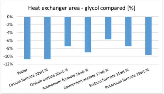
Finally, results from MATLAB simulation are presented. Fig. VI shows the heat exchanger area, for each secondary fluid, to keep an evaporator load equal to 6000 W. The commonly used propylene glycol is the fluid which requires the biggest evaporator and, therefore, the most expensive in terms of money. Cesium formate 32 wt-% has the same value of water, which is an outstanding result. The other secondary fluids perform better than propylene glycol but worse than water and cesium formate. Furthermore, Fig. 8.2 shows the percentage savings of exchanger area, when another secondary fluid is chosen over propylene glycol.
Figure VI - Heat exchanger area for different secondary fluids, in percentage.
Fig. VI shows that choosing cesium formate over propylene glycol, as a secondary fluid, allow to save more than 10% in terms of heat exchanger surface area. Potassium formate and ammonium formate are also good alternatives, giving more than 8 % savings in evaporator heat transfer area.
Fig. VII shows the pressure drop of the secondary fluid in the heat exchanger, compared in percentage to propylene glycol 25.4 wt-% results.
Figure VII - Pressure drop in the heat exchanger for different secondary fluids, in percentage.
Fig. VII shows that using water, rather than propylene glycol 25.4 wt-%, results in over 45% savings in terms of pressure drop, which is directly related with pumping power and electricity used by the circulating pumps. Furthermore, using cesium formate 32 wt-%
instead of propylene glycol 25.4 wt-% results in over 25 % pumping electricity savings having, at the same time, better heat transfer which results in smaller heat exchanger and even more savings. Ammonium formate 16 wt-% and potassium formate 19 wt-% have great results, showing almost 35 % savings in terms of pressure drop, respect to propylene glycol 25.4 wt-%. Cesium acetate 30 wt-% and sodium formate 15 wt-% have similar results to cesium formate, with ammonium acetate 17 wt-% having the worst savings, due to high viscosity.
Conclusions and future works
The thesis has obtained good results respect to previously set goals. Cesium formate is the most promising salt, in terms of heat transfer performances, thanks to outstanding low viscosity and high density. However, cesium formate has some drawbacks, such as low thermal conductivity and low specific heat capacity. Moreover, cesium formate has a price of 2 €/g (Sigma-Aldrich, 2018a) which strongly limit its implementation. However, the price it is expected to drastically decrease as it will be widely used. Cesium acetate has similar properties to cesium formate but it is cheaper and it could be therefore a good alternative, especially when considered for blending with other secondary fluids. Ammonium acetate tuned to be a not so good secondary fluid, due to high viscosity. Ammonium formate has good heat transfer performances and it is also inexpensive. However, it is strongly corrosive and further studies are necessary to implement antioxidants.
There are many possible future work after this thesis work. Corrosion tests for cesium formate and cesium acetate are ongoing and results will be ready soon after the publication of this thesis. Since cesium formate benefit of very good thermophysical properties but is expensive, an expected development would be the blending with other secondary fluids. Once blended, even in small weight percentage, the thermophysical properties have a high margin of improvement. Another possible development should be a more accurate simulation of a ground source heat pump (GHSP) for a single house. It would be interesting to see how it performs over a year of work, calculating the seasonal performance factor and comparing it to an equal system with propylene glycol, ethyl alcohol and potassium formate solutions. Moreover, in the next steps at KTH Royal Institute of Technology, the studied secondary fluids will be tested in loco in a real ground source heat pumps, collecting all the necessary data.
T
ABLE OFC
ONTENTS Acknowledgements ... 3 Extended abstract ... 5 Table of Contents... 15 Sommario ... 21 Abstract ... 23 Introduction ... 25 Objective... 26 Thesis outline... 26Energy and environmental aspects of the refrigeration sector... 27
1.1 Energy consumption of the refrigeration sector ... 27
1.1.1 Emissions from the refrigeration sector ... 28
1.2 Climate Change... 29
1.2.1 Montreal Protocol ... 29
1.2.2 Kyoto Protocol... 29
1.2.3 Regulation (EU) No 517/2014 (F-gas regulation) ... 31
1.2.4 Paris agreement... 34
1.2.5 Kigali amendment... 35
1.3 High GWP refrigerants ... 36
1.4 Low GWP refrigerants... 36
1.4.1 Natural refrigerants... 38
2.2 Indirect refrigeration systems ... 44
2.2.1 Open and closed indirect systems ... 46
2.3 Advantages and drawbacks of indirect refrigeration systems ... 47
2.3.1 Advantages of indirect refrigeration systems... 47
2.3.2 Drawbacks of indirect refrigeration systems ... 47
2.4 Applications of indirect refrigeration systems... 48
2.4.1 Ground Source Heat pumps ... 48
2.4.2 Solar enhanced ground source heat pumps ... 49
2.4.3 Seasonal storage ... 51
2.4.4 Supermarkets ... 53
2.4.5 Ice Rinks ... 54
Secondary fluids for indirect Refrigeration systems...55
3.1 Definition of secondary fluid... 55
3.2 Choice of a secondary fluid ... 55
3.2.1 Characteristics of an ideal secondary fluid ... 56
3.2.2 Equipment compatibility ... 56
3.3 State of the art... 56
3.3.1 Glycols... 56
3.3.2 Chlorides ... 57
3.3.3 Alcohols ... 58
3.3.4 Salts ... 59
3.3.5 Ice slurries... 60
3.4 GHSP market for secondary fluids ... 60
3.4.2 Sweden ... 61
3.4.3 Italy... 62
3.4.4 United States... 62
Measurements... 65
4.1 Methodology and limitations ... 65
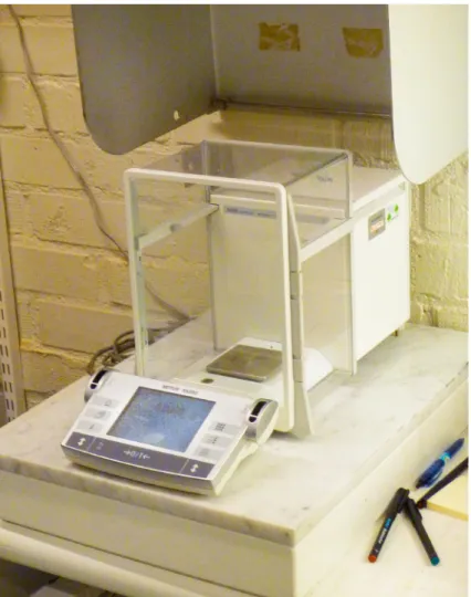
4.2 Tests equipment ... 66
4.2.1 Freezing point measurement device ... 66
4.2.2 Density measurement devices ... 69
4.2.3 Dynamic viscosity measurement device ... 76
4.2.4 Specific heat capacity ... 78
4.2.5 Thermal conductivity measurement device... 79
4.2.6 Refractivity index measurement device ... 82
4.2.7 Corrosion tests... 84
4.3 Error analysis ... 86
4.3.2 Freezing point... 87
4.3.3 Density ... 88
4.3.4 Viscosity... 88
4.3.5 Specific heat capacity ... 89
4.3.6 Thermal conductivity ... 90
Investigated salts ... 91
5.1.1 Lithium formate ... 91
5.1.2 Lithium acetate ... 91
5.1.5 Sodium formate ... 92 5.1.6 Cesium formate ... 92 5.1.7 Cesium acetate ... 92 Results...93 6.1 Freezing point ... 93 6.2 Density test ... 94
6.3 Dynamic viscosity test... 95
6.3.1 Dynamic viscosity of secondary fluids having -10 °C freezing point... 96
6.3.2 Dynamic viscosity of secondary fluids having -20 °C freezing point... 97
6.3.3 Dynamic viscosity of secondary fluids having -30 °C freezing point... 98
6.4 Specific heat capacity test... 99
6.4.1 Cesium formate ... 99
6.4.2 Specific heat capacity of secondary fluids having -10 °C freezing point.... 100
6.4.3 Specific heat capacity of secondary fluids having -20 °C freezing point.... 101
6.4.4 Specific heat capacity of secondary fluids having -30 °C freezing point.... 102
6.5 Thermal conductivity test ... 103
6.5.1 Thermal conductivity of secondary fluids having -10 °C freezing point... 103
6.5.2 Thermal conductivity of secondary fluids having -20 °C freezing point... 104
6.5.3 Thermal conductivity of secondary fluids having -30 °C freezing point... 105
6.6 Corrosion tests ... 106
6.6.1 Stainless steel ... 106
6.6.2 Copper ... 107
6.6.3 Brass... 109
6.6.5 Carbon steel... 111
Numerical performance study ... 113
7.1 Equations ... 113
7.2 Results... 114
7.2.1 Freezing point -10 °C ... 115
7.2.2 Freezing point -20 °C ... 118
7.2.3 Freezing point -30 °C ... 121
7.2.4 Comparison to water heat transfer coefficient at 0 °C... 123
7.2.5 Comparison with water pumping power at 0 °C ... 125
7.3 Matlab evaporator simulation ... 126
7.3.1 Methodology ... 126 7.3.2 Results... 127 Conclusions ... 131 8.1 Future works ... 133 Index of figures ... 135 Index of tables ... 139 Nomenclature ... 141 References... 145
S
OMMARIOLa produzione di freddo ha una grande quota nel consumo energetico mondiale, si stima che la refrigerazione e il condizionamento dell'aria rappresentino circa il 10% delle emissioni globali totali di CO2. Sin dai protocolli di Montreal (1987) e Kyoto (1997), l'interesse per i
refrigeranti secondari e per i sistemi di refrigerazione indiretta è cresciuto come alternativa ai classici sistemi di refrigerazione che utilizzano CFC, CHFC e HCF, dannosi per l'ambiente a causa dei loro elevati GWP e ODP. Il sistema di refrigerazione indiretto può minimizzare la carica del refrigerante primario in modo significativo attraverso l'uso di un refrigerante secondario. Tra i refrigeranti secondari disponibili, le soluzioni a base di sali hanno grande importanza, grazie alle loro buone proprietà termodinamiche e di scambio termico. Lo scopo di questa tesi è di cercare nuovi refrigeranti secondari, a base di sale, studiandone la stabilità, i livelli di solubilità e le proprietà termofisiche più importanti. L'analisi del formiato di cesio evidenzia un'elevata densità e bassa viscosità rispetto a glicoli, alcoli e persino altre soluzioni a base di sale. Il test di corrosione ha evidenziato il comportamento altamente corrosivo del formiato di ammonio, nonostante le ottime proprietà termofisiche. Le simulazioni MATLAB hanno evidenziato che la scelta del formiato di cesio al posto del glicole propilenico, come fluido secondario, consente di risparmiare più del 10% in termini di superficie di scambio termico nell’ evaporatore.
KEY WORDS: fluidi secondari, acetati di sale, formiati di sale, sistema di refrigerazione indiretto, pompa di calore, proprietà termofisiche.
A
BSTRACTThe cooling production has a big share in the world energy consumption, it is estimated that refrigeration and air conditioning accounts for around 10% of total global CO2 emissions.
Since the Montreal (1987) and Kyoto (1997) protocols, the interest in secondary fluids and indirect refrigeration systems has grown as an alternative to classic direct refrigeration systems with CFCs, CHFCs and HCFs refrigerants which can be harmful for the environment due to their high GWP and ODP. The indirect refrigeration system can minimize the charge of harmful primary refrigerant significantly through the use of secondary fluids. Among the available secondary fluids, salt-based solutions have an important relevance, because of their good thermodynamic and heat transfer properties. The aim of this thesis is to search for new salt based secondary fluids by investigating the stability, solubility levels as well as the most important thermophysical properties. Cesium formate analysis highlight outstanding high density and low viscosity compared to glycols, alcohols and even other salt-based solutions. Corrosion test pointed out the highly corroding behavior of ammonium formate in spite of its very good thermophysical properties. MATLAB simulations pointed out that choosing cesium formate over propylene glycol, as a secondary fluid, allow to save more than 10% in terms of heat exchanger surface area. KEY WORDS: secondary fluids, acetate salts, formate salts, indirect refrigeration system, heat pump, thermophysical properties.
I
NTRODUCTIONRefrigeration has always been a priority in human life for food conservation and air conditioning. Nowadays the cooling demand in building is quickly increasing, especially in cooling dominated developing zones of the planet.
In the very last decades, international agreements such as Montreal (1987) and Kyoto (1997) protocols have highlighted the non-environmental friendly behavior of classic refrigerants. The aim of the first protocol was to phase out chlorofluorocarbons (CFCs) and hydrochlorofluorocarbons (HCFCs), which stay for many years in the atmosphere due to their inert behavior. HCFCs and CFCs react under the presence of ultraviolet radiation, releasing chlorine, a catalyst for the decomposition of ozone into molecular oxygen (Molina and Rowland, 1974). The second protocol focused instead on the reduction of greenhouse gases (GHGs) emissions in order to keep the overall planet mean temperature difference within two degrees, compared to the pre-industrial times.
Nowadays the use of primary refrigerants is strictly legislated and controlled. There are EU laws, such as the F-gas regulation (lastly updated in 2015), which aims at minimizing the actual impact of the refrigerants and to slowly move the market toward the use of low Global Warming Potential (GWP) refrigerants.
In this context, indirect cycles can be of some help in reducing the use of high GWP refrigerants which, in turn, reduces their presence into the systems significantly (Melinder, 2015). This can be done by the mean of a secondary loop used to transport and transfer heat from the primary refrigeration loop to the entity that needs to be cooled. The indirect refrigeration systems are already used in a high variety of applications such as: cooling purposes in supermarkets; ice rinks; heat recovery systems; ground source heat pumps and other refrigeration systems (Melinder, 2007).
One of the most important aspect to consider while studying the secondary fluids is their thermophysical behavior at different operational conditions. In particular, it is important to know thermophysical properties i.e.: density, viscosity, specific heat, thermal conductivity, volumetric heat capacity and freezing point temperature. Furthermore, other properties of secondary fluids are of high importance from the system design point of view, i.e.: toxicity, stability, biodegradation time, foaming factor, flammability, material compatibility, etc.
Objective
The aim of this thesis is to measure and validate the thermophysical properties of some new formate and acetate based secondary fluids in order to propose better performing low temperature alternative solution which can be used together with low GWP refrigerants. This study contributes to develop more environmentally friendly and non-flammable solutions and helps in fighting the global warming preserving the environment, as we know it, for the generations to come.
Thesis outline
The thesis is organized as follows:
Chapter 1 discusses the energy and environmental aspects of the refrigeration sector, focusing on climate change, legislations, emissions of CO2and types of refrigerant fluids on
the market.
Chapter 2 discusses the configuration and working principles of indirect refrigeration systems, compared to direct one. Furthermore, it gives an overview of the applications. Chapter 3 discusses the types of secondary fluids fluids, the principles that leads to the choice of one secondary fluids and their diffusion worldwide.
Chapter 4 describes the laboratory instruments, the methodology used for performing the measurements and an error analysis to validate the data.
Chapter 5 gives an overview on the nowadays information available on the studied secondary fluids.
Chapter 6 presents and comments the results of the measurements.
Chapter 7 discuss the results of a MATLAB simulation run for comparing the performances of each Secondary fluid in an evaporator. Furthermore, discuss the results of an excel study, to find the heat transfer characteristic of each Secondary fluid in a U-borehole pipe installation.
Chapter 8 presents the conclusions of the study and introduce some of the possible future works.
E
NERGY AND ENVIRONMENTAL ASPECTS OF THE REFRIGERATION SECTORFor the majority of the people the world “refrigeration” brings to mind: household refrigerators, refrigerated display cabinets in supermarkets, ice rinks, air cooling systems and snowmaking systems. However, those are just some of the many applications of the refrigeration industry, which is present in countless sectors and plays a major role for healthcare, energy and the environment.
1.1 Energy consumption of the refrigeration sector
The total number of refrigeration, air conditioning and heat pump systems in operation worldwide is roughly 3 billion, including 1.5 billion of domestic refrigerators. The refrigeration sector consumes 17 % of the world electricity production (Coulomb and Dupont, 2015) and this number is expected to increase in the coming years due to different factors i.e.: increasing refrigeration demand, growing of undeveloped countries (especially the ones in warm climates) and global warming. As seen in Fig. 1.1 there is still an unbalance, among the continents, in the electricity consumption for refrigeration needs and refrigeration capacity will increase in the years to come.
Figure 1.1 - Distribution of electricity consumption for refrigeration (kWh.year/capita).
Acronymus present in Fig. 1.1, NAM: North America; PAO: Pacific OECD; WEU-EEU: Western, Central and Eastern Europe; FSU: Independent states of the former Soviet Union; MEA: Middle East and North Africa; LAM: Latin America and the Caribbean; CPA: Centrally planned Asia and China; SAS-PAS: South Asia – Other Pacific Asia; AFR: Sub-Saharan Africa (Coulomb and Dupont, 2015).
1.1.1 Emissions from the refrigeration sector
Refrigeration technologies and especially heat pumps are considered as green and sustainable technologies. However, the refrigeration systems generate global warming themselves by 20 % due the direct leakage of refrigerants with high GWP from the refrigeration system into the atmosphere and 80 % due to indirect emissions of electricity production, production and transportation (Coulomb and Dupont, 2015).
Considering the space refrigeration sector, researchers at Lawrence Berkeley National Laboratory estimate the global stock of room air conditioners will rise by an additional 700 million by 2030, and 1.6 billion by 2059 (Shah et al., 2015). And according to another forecast, by the end of the century global air conditioning will consume 10,000 TWh about half the electricity consumed worldwide for all purposes in 2010 (IPCC Fifth Assessment
Report, 2014).
Moreover, it is also estimated that one third of the world food production is getting spoiled or lost. The food during its life span produces CO2, from the earliest phases of production to
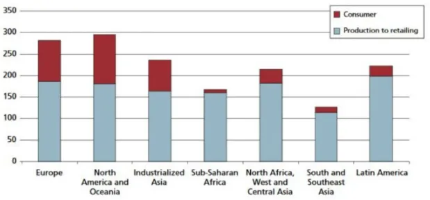
the deterioration process (Eriksson et al., 2015). Thus, decreasing the food waste through improving refrigeration, contributes to the climate change alleviation. Fig. 1.2 shows that 90 % of the food waste occurs in the supply chain, in developing countries.
Figure 1.2– 90 % of food wastage in developing countries occurs in the supply chain (Strahan, 2015).
The lack of adequate cold chains of refrigerated warehousing and transport causes the waste of 200 million tons of food with consequences far beyond hunger and inflated food prices. Food wastage occupies a land area almost twice the size of Australia; three times the volume of Lake Geneva; and emits 3.3 billion tons of CO2, making it the third biggest emitter after the US and China (Strahan, 2015). Hence, improving the existing refrigeration technologies
1.2 Climate Change
The scientific community is jointly convinced that human activities are the cause of global warming, with a 97 % consensus among scientific articles and publications (Cook et al., 2016). It is evident that a change is required to benefit the planet in a sustainable way and grant the safety of human life. Thus, plenty of measures has been taken over the past years. 1.2.1 Montreal Protocol
The Montreal Protocol is an international agreement signed in 1987 as an outcome of the Vienna Convention. It aims to protect the ozone layer by phasing out of various substances responsible for the ozone depletion.
Figure 1.3 - Production of halogenated refrigerants (Harby, 2017).
As shown in Fig. 1.3, the effectiveness of the protocol was immediate and in 10 years’ time the production of halogenated refrigerants was completely phased out. In fact, due to its widespread adoption and implementation it has been welcomed as an example of exceptional and most successful international co-operation in history.
1.2.2 Kyoto Protocol
The Kyoto Protocol is an international agreement which aims to reduce the global warming effect and mitigate the climate change. It was adopted in Kyoto, Japan, on 11 December 1997 and entered into force on 16 February 2005. It concerns the fact that humans are causing global warming by the emission of GHGs into the atmosphere.
The aim of the agreement is to reduce emissions and concentration of GHGs to keep the temperature increase lower than 2 degrees compared to the pre-industrial period. Furthermore, the Protocol is based on the principle of “common but differentiated responsibilities”; i.e. the more developed countries should have more responsibilities because they are historically responsible for the current levels of GHGs in the atmosphere, because of more than 150 years of industrial activity. Fig. 1.4 below shows the graphical evidence of this industrial activity.
Figure 1.4 - Cumulative CO2emissions from 1850 to 2011 (% World Total) (World Resources Institute, 2014).
In order to make the change economically sustainable the protocol introduces some economic tools to support every country in achieving these goals: International Emissions Trading (IET), the Clean Development Mechanism (CDM), and Joint Implementation (JI). The IET makes possible to “trade” the emissions on the international market (World Resources Institute, 2014)
1.2.3 Regulation (EU) No 517/2014 (F-gas regulation)
The F-gas regulation came into action 1 January 2015 and introduced a number of important changes such as: limitation of the amount of F-gases that can be sold in the European Union; banning the use of F-gases in new types of equipment where more environmentally alternatives are available; and the prevention of emissions of F-gases through proper recovery of gases; more restricted controls and service requirements on existing equipment (European Parliament, Council of the European Union, 2014a).
The aim of F-gas regulation is to reduce the usage of high GWP refrigerants. Thus, some measures have been introduced which became more important, in Tab. 1.1 is reported the placing on the market prohibitions of the (European Parliament, Council of the European Union, 2014b), F-gas regulation.
Table 1.1– Annex III of EU Regulation No 517/2014 (European Parliament, Council of the European Union, 2014b).
Products and equipment Date of
prohibition Non-refillable containers for fluorinated greenhouse gases used to
service, maintain or fill refrigeration, air-conditioning or heat-pump equipment, fire protection systems or switchgear, or for use as solvents
4 July 2007
Non-confined direct evaporation systems that contain HFCs and PFCs as refrigerants
4 July 2007
Fire protection equipment that contain PFCs 4 July 2007
that contain HFC-23 1 January 2016 Windows for domestic use that contain fluorinated greenhouse gases 4 July 2007
Other windows that contain fluorinated greenhouse gases 4 July 2008
Footwear that contains fluorinated greenhouse gases 4 July 2006
Tyres that contain fluorinated greenhouse gases 4 July 2007
One-component foams, except when required to meet national safety standards, that contain fluorinated greenhouse gases with GWP of 150 or more
4 July 2008
Aerosol generators marketed and intended for sale to the general public for entertainment and decorative purposes, as listed in point 40 of Annex XVII to Regulation (EC) No 1907/2006, and signal horns, that contain HFCs with GWP of 150 or more
4 July 2009
Refrigerators and freezers for commercial use (hermetically sealed equipment)
that contain HFCs with GWP of 2500 or more 1 January 2020 that contain HFCs with GWP of 150 or more 1 January 2022
Stationary refrigeration equipment, that contains, or whose functioning relies upon, HFCs with GWP of 2500 or more except equipment intended for application designed to cool products to temperatures below – 50 °C
1 January 2020
Multipack centralised refrigeration systems for commercial use with a rated capacity of 40 kW or more that contain, or whose functioning relies upon, fluorinated greenhouse gases with GWP of 150 or more, except in the primary refrigerant circuit of cascade systems where fluorinated greenhouse gases with a GWP of less than 1500 may be used
1 January 2022
Movable room air-conditioning equipment (hermetically sealed equipment which is movable between rooms by the end user) that contain HFCs with GWP of 150 or more
1 January 2020
Single split air-conditioning systems containing less than 3 kg of fluorinated greenhouse gases, that contain, or whose functioning relies upon, fluorinated greenhouse gases with GWP of 750 or more
1 January 2025
Foams that contain HFCs with GWP of 150 or more except when required to meet national safety standards
Extruded polystyrene (XPS)
1 January 2020
Other foams 1 January 2023
Technical aerosols that contain HFCs with GWP of 150 or more, except when required to meet national safety standards or when used for medical applications
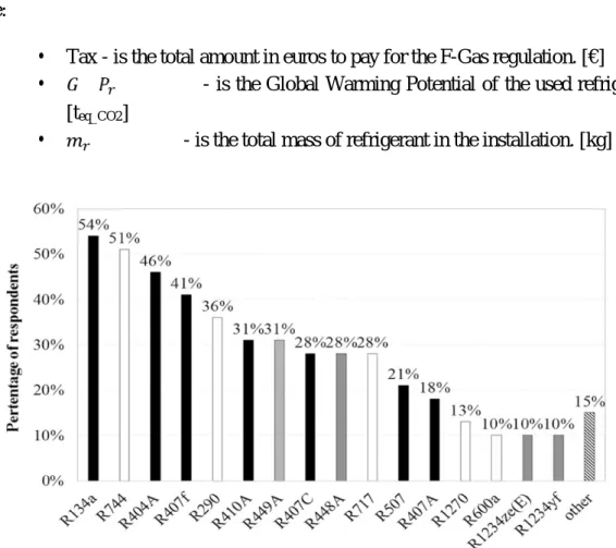
Furthermore, a tax on the installation of high GWP refrigerants is introduced and calculated using eq. 1
= 0,02 ∙ ∙ (€) 0,02 ∙ ≤ 100 (1)
Where:
Tax - is the total amount in euros to pay for the F-Gas regulation. [€]
- is the Global Warming Potential of the used refrigerant.
[teq_CO2]
- is the total mass of refrigerant in the installation. [kg]
Figure 1.5 - Percentage of questionnaire respondents indicating a refrigerant as currently installed or used for commercial refrigeration by companies (Mota-Babiloni, 2017).
However, as seen in Fig. 1.5, R-134a is still the most used refrigerant, especially due to retrofitting problems in already existent VCSs. Therefore, there is still work and research to be done to find new refrigerants and alternative solutions.
Furthermore, F-gas regulation introduce the limitation on quotas of high GWP refrigerants allowed to be places on the market, decreasing this percentage according to Fig. 1.6 chart.
Figure 1.6 - Phasing down of high GWP refrigerants quotas (European Parliament, Council of the European Union, 2014a, p.).
As it is visible in Fig. 1.6 the pashing down is expected to be -79 % by the year 2030. 1.2.4 Paris agreement
Paris agreement has been signed on 12 December 2015 in Paris, France. It took over the duties of old Kyoto Protocol and fits them to the new global situation. This time all of the nations were expected to contribute in the reduction of GHG emissions. There was no specific goal or deadline defined but each target should be prioritized beyond previously set targets and contribute, jointly with the others 159 participators, to keep the temperature increment well below two degrees from pre-industrial times.
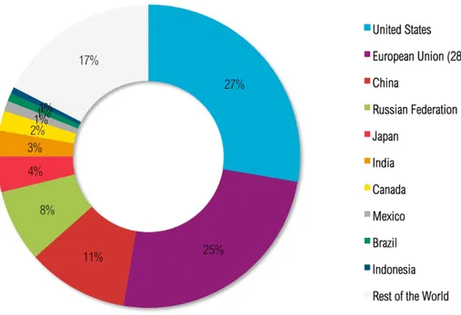
As seen in Fig. 1.7 it is evident that United States, China and the EU countries are still the most carbon emitting countries and they should work as a “lighthouse” for the other nations in terms of technologies and smart solutions for achieving the goals of the Paris agreement. However, on 1 June 2017, U.S. President Donald Trump announced that the United States would withdraw from the agreement. On the other hand, there are countries with ambitious projects; e.g. Swedish government announced that will end sales of petrol and diesel vehicles by 2020 as part of the plan to meet its targets, France wants to do the same by 2040 and Volvo will produce only electric or hybrid card by 2019.
It is important to point out that the Paris agreement targets will be applied starting from 2020. Therefore, today the Paris agreement is a powerful framework, which needs to be completed and refined to obtain the maximum advantage.
1.2.5 Kigali amendment
The Kigali amendment was adopted by all parties of the Montreal protocol, in October 2016. The purpose of the treat is to limit and regulate the production of HFC gases in order to fight against climate change. HFCs are non-ozone depleting gases which were first introduce in the 90s as alternatives to CFCs and HFCs already banned after the Montrel Protocol. The Kigali amendment defines HFC phase-down schedules for four different Party groups, according to their development and climate conditions. (Höglund-Isaksson et al., 2017), made an estimation of the total abetment cost of HFCs, considering the 4 different parties group; the study estimated that compliance with the Kigali amendment is expected to remove 61 % of global baseline HFC emissions, for the entire period 2018-2050. Depending on the expected rate of technological development and the extent to which envisaged electricity savings can be realized, the global cost of compliance is estimated to range from a net cost-saving of 240 billion € to a net cost of 350 billion € for the period 2018 to 2050.
1.3 High GWP refrigerants
Among all refrigerants carbon dioxide, CO2 has a GWP equal to one and is used as a
reference for all other GHGs to attribute their respective GWP. Table 1.2 below presents the most commonly used high GWP refrigerants available on market.
Table 1.2 - Some popular high GWP refrigerants (Stocker, 2014).
ASHRAE Name Formula GWP (100 yrs) Phasing Out CFC-12 CCl2F2 8100 1994 HCFC-22 CHF2Cl 1500 2010-2015 HFC-134a CH2FCF3 1430 2011-2017 HFC-404A 0,44 R125 – 0,04 R134a – 0,52 R143a 3922 2020-2030 HFC-410A 0,5 R32-0,5 R125 2088 2024
Of course, there are plenty of new blends of synthetic refrigerants being a mixture of CFCs and HFCs to have smother phase out process of CFCs for different applications and sectors. Moreover, the phasing out dates for different refrigerants reshape the market and laws to comply the existing international agreements.
However, it is of high importance to take into account the refrigerant’s total life cycle, its properties, flammability and temperature glide. Thus, in the moment of choosing the most suitable refrigerant it is suggested to look at the Total Equivalent Warming Impact (TEWI), which considers the indirect emissions related to electricity use. TEWI method it is not standard and changes according to each case study.
1.4 Low GWP refrigerants
In order to adapt to the new protocols and laws the market is coming with new low GWP solutions. Those new refrigerants should be able to work with good COP, close or even higher to the old ones and used in the old systems with no huge investments. New solutions currently trying to be implemented on the market are showed in this chapter.
McLinden et al. (2014) studied thermodynamically all the low GWP refrigerants adapt for refrigeration and air-conditioning use, resulting in 62 candidate fluids, most of them flammable; from these fluids, none is ideal in all regards and trade-off should be performed. The refrigerant mixtures could address these trade-offs because of the resulting intermediate properties, especially flammability and GWP.
Morover, McLinden et al. (2017) made a screening of pure fluids which possess the combination of chemical, environmental, thermodynamic, and safety properties necessary for a refrigerant. For the fluids passing the thermodynamic and environmental screens they
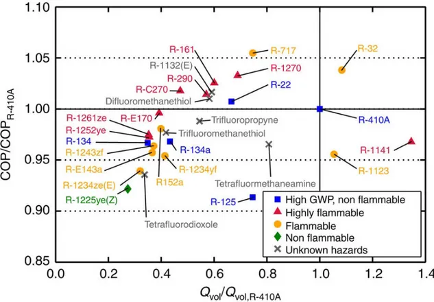
heat exchangers. The study focused on COP and volumetric heat capacity, comparing them to the ones of R410A, a commonly used refrigerant as is shown in Fig. 1.8.
Figure 1.8 - Coefficient of performance and volumetric capacity of selected low-global-warming-potential fluids (McLinden et al., 2017).
Fig. 1.8 shows that there are higher COP alternatives to R410A, but with flammability issues; the only fluid which has better COP and volumetric heat capacity is the R32 (difluoromethane), which is already implemented by some AC producers. However, this has still a barely high GWP of 632 and is slightly flammable.
Domanski et al. (2017) studied low-GWP refrigerants alternatives for medium and high-pressure applications, the study shows that the low-GWP refrigerant options are very limited, particularly for fluids with volumetric capacities similar to those of R-410A or R-404A.
1.4.1 Natural refrigerants
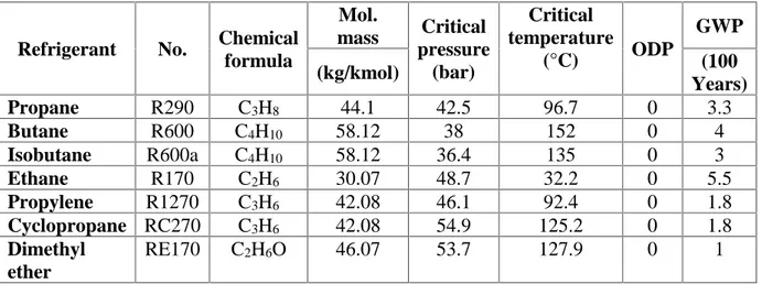
At the dawn of refrigeration technology cooling was provided with every fluid that could work i.e.: water, ammonia, carbon dioxide and hydrocarbons due to easy availability in nature. Table 1.3 presents the thermodynamic and environmental properties of hydrocarbons that are most frequently investigated as refrigerants.
Table 1.3 - Thermodynamic and environmental properties of hydrocarbons that are most frequently investigated as refrigerants (Harby, 2017).
Refrigerant No. Chemical
formula Mol. mass Critical pressure (bar) Critical temperature (°C) ODP GWP (kg/kmol) (100 Years) Propane R290 C3H8 44.1 42.5 96.7 0 3.3 Butane R600 C4H10 58.12 38 152 0 4 Isobutane R600a C4H10 58.12 36.4 135 0 3 Ethane R170 C2H6 30.07 48.7 32.2 0 5.5 Propylene R1270 C3H6 42.08 46.1 92.4 0 1.8 Cyclopropane RC270 C3H6 42.08 54.9 125.2 0 1.8 Dimethyl ether RE170 C2H6O 46.07 53.7 127.9 0 1
However, those substances were highly toxic or flammable. Hence, the marked turned to more stable and safer refrigerants (CFCs). After the discovery of ozone depilation and global warming effect, natural refrigerants gained new interests again due to their zero ODP and very low GWP.
1.4.1.1 Ammonia
Ammonia (R717) is a colorless fluid with a distinguishing pungent odor. It was used for the first time as refrigerant in 1876 due to its good thermodynamic properties. Ammonia as refrigerant resisted against the rise of CFCs, especially in large industrial installations and food preservation due to good thermodynamic properties.
Moreover, ammonia in its gas phase is lighter than air and slightly flammable. It can be easily liquefied due to the strong hydrogen bonding between molecules. Additionally, ammonia is highly soluble in water. The physical properties of ammonia compared to water show that ammonia has lower melting point, boiling point, density and viscosity due to the weaker hydrogen bonding in the molecule. Ammonia is highly toxic to humans and other living organisms (Ignatowicz, 2008). It has a high latent heat, good thermophysical properties and a cheap purchase cost. Therefore, it provides low energetic consumption and a high COP. However, due to his toxicity, the systems must have an emergency outdoor, forced ventilation system, breathing protection system, leakage detection sensors and water providing system (Fernandéz, 2016).
Aqueous solutions of ammonia have very good thermophysical properties down to temperature of -55°C making possible to use it either as a primary (pure) or secondary (solute in water) working fluid (Melinder, 2007).
1.4.1.2 Propane
Propane (R290) is an odorless, colorless, safer compared to ammonia refrigerant with good thermophysical properties. However, it was forbidden as refrigerant in the past few decades due to its flammability. Recently propane acquired renewed interest as an alternative refrigerant to CFCs and HFCs causing the global warming. As reported by (Choudhari and Sapali, 2017) propane has a GWP of 3, ODP of 0 and an atmospheric lifetime of only 15 days. R290 as a primary refrigerant can be an efficient substitute of R22 in retrofitted refrigeration systems.
Furthermore, compared to classic primary refrigerants, propane has better heat transfer performance (Park et al., 2005) and better efficiency in some applications (Kauffeld, 2016). Choudhari and Sapali (2017) studies R290 as a substitute of R22, finding that refrigerant mass flow rate required with R290 is lower by 50 % compared to R22, having the same COP. Furthermore, higher COP can be expected by especially designed system pertaining to the properties of R290.
Finally, even though propane is flammable, it should be remembered that millions of tons of hydrocarbons substances are used safely over the world for cooking, heating, powering vehicles, aerosol propellants etc.
1.4.1.3 Iso-butane
Isobutane (R600a) is an odorless, colorless refrigerant; it has similar properties to propane and is often used mixed with it. Due to its flammability is important to safely design the system. R600a is the standard refrigerant for European and many Asian domestic refrigerators and freezers. Over 40 million appliances are produced annually with isobutane worldwide (Kauffeld, 2016). Rasti et al. (2012) used R600 mixed with R290 as an alternative to R134a in a domestic refrigerator, with better energy performances.
1.4.1.4 Carbon dioxide
Carbon dioxide (R744) is the biggest GHG gas present in the atmosphere and is the major cause of the global warming effect. On the other hand, carbon dioxide is a good and environmentally friendly refrigerant with a very low GWP of 1. In fact, it is unique due to its safety, non-flammability, relative non-toxicity, low costs and compatibility with most materials (Sawalha and Palm, 2000).
The working of CO2cycle is different from other conventional refrigerant based subcritical
cycles due to its low critical temperature (31.2 °C) with relatively higher critical pressure (73.8 bar). Subsequently, at normal operating temperature range, the system needs to operate at high pressure, typically 5-10 times higher than that of conventional refrigerants. Thus, the pipes have to be properly designed and it is suggested not to use plastic ones (Ignatowicz, 2008). In fact, there are also trans critical cycles, with pressures above 100 bars which allow very good heat transfer and high heat recovery rate leading to high COP.
Another important aspect to consider when choosing CO2 as refrigerant is the outdoor
temperature. In fact, the performance of the system becomes more sensitive, when it is operated in warm climatic conditions, and the COP yields drastically decreases with increasing the operating environmental temperature (Gupta et al., 2010).
To overcome the high power required at the compressor in a CO2 cycle, recent studies has
proposed to use parallel compression; with efficiency increments up to 10 % (Fritschi et al., 2017).
It is interesting how CO2, and ammonia/ammonia-water, can be used both as a primary and
secondary fluids. Making available several different configurations for adapting to different purposes.
1.4.2 Synthetic low GWP refrigerants
Beside natural refrigerants, the market is trying to answer the needs of industry by introducing new synthetic refrigerants with low GWP. Research is focusing mostly on 2,3,3,3-tetrafluoropropene (R1234yf) and 1,3,3,3-tetrafluoropropene (R1234ze). Those new refrigerants will be the substitutes of the actual R-134a for Mobile Air Conditioning (MAC) applications. In fact, in the MAC about 80 % of total direct emissions are due to R134a (GWP of 1430) which is still used to high extend. These direct emissions are mostly related to leakages due to the high service rate and non-recyclability of refrigerants (Su et al., 2015). Lee et al. (2015) obtained the largest COP using R1234yf (compared to R134a, R152a, R444A, and R445A). According to Li et al. (2014) the COP of R152a in an indirect refrigeration system (instead of the evaporator, an intermediate fluid is used to cool the space concerned) is between 5 and 10 % higher than that of R134a in a direct expansion system. The proposed system also offers 34 % reduction in refrigerant charge.
In case of domestic refrigeration, flammability is a key factor in the choice of a low GWP refrigerant, thus countries with stronger safety regulations prefer to use less flammable refrigerants to replace R134a. While in the United States the charge of hydrocarbons in domestic refrigeration systems is limited to 57 g, in the EU the limit is 150 g. In Japan, for example, the use of R600a instead of R134a has been shown to be able to reduce the global warming impact from 2022 kt CO2-eq. in 1998 to 72 kt CO2-eq. in 2030 (Mota-Babiloni et
al., 2017; Xue et al., 2017).
To overcome the flammability issue market is responding with mixtures of R1234yf and R134a (Aprea et al., 2017).
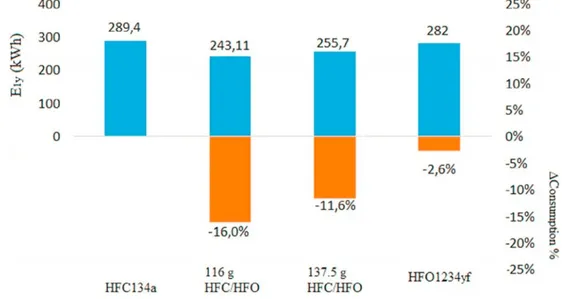
Figure 1.9 - Yearly electric energy consumption and energy saving for the refrigerant fluids in a 24-hour test (Aprea et al., 2017).
In Fig. 1.9 Aprea et al., (2017) presents the results from a performance comparison using different mixtures of R1234yf and R134a. The charge of 116 g is better than 137.5 g because it achieves: i) a lower condensing pressure (−6 %) and ii) a lower energy consumption (−5 %). Furthermore, the lower charge (−16 %) ensures cost saving because HFO1234yf is a very expensive refrigerant. Therefore, the mass of 116 g can be considered the optimal charge of HFO1234yf/HFC134a (90/10 wt-%) and it best reproduces the behaviour of the refrigerator when it operates with R134a.
D
IRECT AND INDIRECT REFRIGERATION SYSTEMSThe purpose of the refrigeration engineering is to maintain the temperature of a cold heat source below the surroundings. This implies transferring the heat from a source with a low temperature to another at a higher temperature.
The most common type of refrigeration system nowadays is the vapor compression refrigeration system (VCRS), patented in 1835 by Jacob Perkins. The main application of refrigeration system is food storage, cooling of machines and electronics, automobiles, indoor climate control, industrial refrigeration, ice rinks, medical application, etc.
Generally speaking, VCR main be classified in direct and indirect systems. In the former, the cold heat source is directly cooled by the VCRS itself whereas in the latter a heat transfer fluid is continuously cooled in the VCRS and heated by the cold heat source. Consequently, in the direct system the VCRS and the cold heat source are close together whereas in the indirect configuration they may be well far each other.
2.1 Direct refrigeration systems
Fig. 2.1 shows the schematic of a simple scheme of the direct vapor compression refrigeration system. Besides the refrigerant, the direct refrigeration system has four main components: evaporator, compressor, condenser and expansion valve.
Figure 2.1 - Simple scheme of a direct VCRS.
1-2: The compressor pressurizes the vapor refrigerant taken from the evaporator. At the same time, due to the compression effect, there is also an increment in temperature and enthalpy, which provides the temperature difference, ΔT for the next step. It may be of different types, e.g. reciprocating, rotary, scroll, screw or centrifugal, according to the type and size of the application.
3-4: Inside the condenser, the refrigerant is cooling down and exchanging the heat at high temperature. The refrigerant temperature must be higher than the one of the cooling medium, which may be air or water.
5-6: The expansion device is a device where pressure is reduced in an isenthalpic way. In this process, the fluid is brought back to the initial temperature and pressure conditions to restart the cycle.
This design is a perfect solution for compact systems, because of its simplicity and compactness. However, for bigger or more complex refrigeration systems it is not the best solutions due to problems related with primary refrigerant charge and leakage.
2.2 Indirect refrigeration systems
The use of an indirect refrigeration systems gained interest due to the results of Kyoto and Montreal protocols because small quantities of high GWP or flammable refrigerants are used and also because an increase in energy efficiency may be achieved (Lee et al., 2015). The principle of the indirect refrigeration system is transferring the heat from the source to cold sink by the means of a secondary fluid. These systems have long been used for applications with several objects to cool or where long pipes are required; e.g. supermarkets, artificial ice rinks, ground source heat pumps, larger slaughter houses, dairies, ect. (Melinder, 2015).
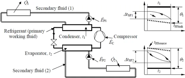
As seen in Fig. 2.3 the indirect refrigeration system design now is more complex. There are one to two more loops, two more heat exchangers and two more pumps, which implies some benefits and some drawbacks.
Figure 2.3 - Complete scheme of an indirect system with temperature profiles (Melinder, 2015)
Explanations of Fig 2.3 nomenclature: Q1= released heat capacity; Q2 = cooling capacity;
EC = compressor power; EP = pumping power; t1 = condensing temp.; t2 = evaporating
temp.; tHSink= heat sink temp.; tHSource= heat source temperature; θ1= temperature difference
between condensing temperature and heat sink; θ2 = temperature difference between heat
source and evaporating temperature: ΔtSF1 and ΔtSF2 are temperature changes of secondary
fluids (1) and (2).
In Fig. 2.2 and 2.3 the basic scheme of an indirect system is shown; however, looking at a real installation the scheme becomes way more complex, e.g. expansion vessels, safety valves, filters, air purging, degassing units, high point air-purge valves (manual and automatic), etc. In Fig. 2.4 a more detail scheme is presented.
Figure 2.4– Advanced scheme of an indirect refrigeration system (Ignatowicz, 2008).
A particular attention must be paid to the maintenance of an indirect system. Indeed, it is very important for keeping high heat transfer performances and, therefore, having high COP and SPF. Furthermore, the introduction of air into the system can cause the largest problems related with breakdown of stability of the solution, thus becoming aggressive, unstable and corrosive to metals (Ignatowicz, 2008).
2.2.1 Open and closed indirect systems
There are two types of indirect system, closed loop and open loop ones. Closed loop system are the most common and they have some practical advantages, e.g. it is easier to remove air, the system pressure can be easily adapted, possibility to use flammable or toxic fluids, etc. Open loop systems are usually used whereas the secondary fluid is water, e.g. in the case of thermal aquifer storage (ATES).
2.3 Advantages and drawbacks of indirect refrigeration systems
2.3.1 Advantages of indirect refrigeration systems
The primary refrigeration unit can be built separately or in factories; small and compact with a minimum refrigerant charge. Those compact units could be produced in large quantities and applied to various purposes. Furthermore, producing small primary cooling systems in large scale increase the efficiency and reduce at minimum leakages and manufacturing cost.
It is possible to isolate the toxic or/and inflammable refrigerant in the main machine room. This allows using high performance refrigerants such as ammonia and hydrocarbons.
Less technical limitations when the cooled space is distant from the machine room. In fact, secondary loops work at lower pressures and temperatures that allow using cheaper plastic pipes. Furthermore, changes in piping and modifications in the system are easy to perform and therefore the system is more flexible.
Flooded evaporators in chillers can be used up to 100 % while in direct refrigeration systems the expansion valve limits the use to 70 % (Melinder, 2007).
For well-designed and performing indirect refrigeration systems, the yearly energy consumption may be less than for the direct one. This is possible due to more even temperature distribution at the cooling object and fewer defrosting procedures. The indirect refrigeration system reduce the primary refrigerant charge drastically
compared to the one of a direct system (Melinder, 2015). 2.3.2 Drawbacks of indirect refrigeration systems
The main drawback of the indirect refrigeration system is higher investment cost, due to extra cost of heat exchangers, pumps, piping and secondary fluid.
Two more temperature differences are introduced which decreases the thermodynamic efficiency of the systems.
2.4 Applications of indirect refrigeration systems
Some examples of applications for indirect refrigeration systems are: geothermal or water to water heat pumps, supermarkets, artificial ice rinks, sport facilities, hospitals, Borehole Thermal Energy Storage Systems (BTES) and heat recovery solutions from industrial production processes. An overview of indirect refrigeration systems follows.
2.4.1 Ground Source Heat pumps
Ground source heat pumps (GSHP), known also as geothermal heat pump systems or geo-exchange systems, represent a more environmentally friendly technology in heating and cooling of buildings. This technology uses the heat stored in the underground as a thermal sink and consequently moves the heat between the underground and the building by the mean of an electricity driver heat pump, a simple scheme of the pipe used to extract energy from the underground is shown if Fig. 2.5. According to Lund and Boyd, (2016) the annual worldwide use of thermal energy produced by ground source heat pumps increased from 4.06 TWh to 90.79 TWh from 1995 to 2015 and in the next year is forecasted to keep drastically increasing.
Figure 2.5 - Example GSHP with 3 vertical boreholes, for a single household.
The COP (Coefficient of Performance) of a GSHP is usually in the range 3–3.8. Different configurations of the ground heat exchanger exploit ground heat source from the surface down to a depth of 450 m (Lucia et al., 2017).
One key factor in the improvement of this technology is the performance of the ground heat exchanger and to obtain precise theoretical model for its design. Indeed, its modelling is very
complex because it requires a long-term steady-state temperature response; consequently, many simplified assumptions are usually introduced (Javed and Fahlén, 2011). Moreover, the heat flow depends also on other factors, i.e. the location and the boreholes thermal relative interaction. The two most critical design quantities are the appropriate length and the balance of the ground loads (Claesson and Javed, 2012).
2.4.2 Solar enhanced ground source heat pumps
The ground can be divided thermally into two layers: the upper section, which is a few meters deep that is affected by external climatic conditions as well as level of urbanization; the lower one, which is crucial for vertical borehole heat exchangers (BHEs) that is thermally stable presenting a similar temperature to the mean annual air temperature of the site. However, the heat extraction or injection cause a decrease or increase in the ground mean temperature, respectively. This phenomenon is the so called “thermal drift” (Emmi et al, 2017).
One way to avoid the thermal drift is to recharge the ground by injecting or extracting heat in order to even the heat balance. This better way is using a cheap source, such as solar thermal collectors or cooling towers as well as solar enhanced GSHP. Kjellsson et al. (2010), reported the results of an ANSYS simulation finding that the optimal strategy is using the heat from the solar collector to produce domestic hot water during the summer and to recharge the borehole in wintertime. Bellos et al. (2016), have simulated and compared four different solar enhanced heat pump configurations, for heating a usual 100 m2 building located in Athens having:
1) PV panel + battery + air source heat pump
2) FPC panel + storage tank + water source heat pump
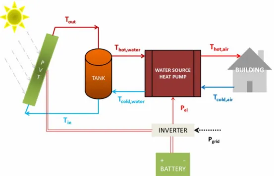
3) PVT panel + battery + storage tank + water source heat pump 4) FPC panel + PV panel + battery + tank + water source heat pump Fig. 2.6 shows configuration number 3.
Figure 2.6 - Configuration 3: PVT panel + battery + storage tank + water source heat pump (Bellos et al., 2016).
This study showed that taking into consideration the sensitivity analysis of the electricity prices up to 0.23 €/kWh the use of PV coupled with an air source heat pump is the most sustainable solution from a financial point of view. Moreover, in case of higher electricity prices, the PVT coupling with water source heat pump is the best choice. In case if the present electricity price stays at the same level of 0.2 €/kWh, PV system having the area of 20 m2is able to drive the air source heat pump with a yearly solar coverage of 67 % leading to the most sustainable solution.
However, it is to consider that those results can be different in colder climes. Nevertheless, solar enhanced ground source heat pumps gain interest in case of thermally balancing the ground, increasing the efficiency of system in densely populated area and extending the lifetime of the drilled boreholes. In fact, distance between the boreholes is a key factor in long-term performance of the heat pump; (Bertram E, 2009), conducted studies on the relationship between solar injections into the ground and the distance between the boreholes. Examining 14 heat exchangers arranged in a rectangular and the various distances between the boreholes, with a heat conductivity of soil of 2 W/mK, the authors concluded that without heat injections the distance between the boreholes had a significant effect on the annual performance factor, which decreased by about 0.5 % from a 15 m distance to 3 m distance. The annual performance factor was not affected by distance when solar regeneration was used. These results are particularly important in the residential energy sector, which is commonly characterized by limited space.
2.4.3 Seasonal storage
2.4.3.1 Large scale borehole installation (BTES)
The benefits of GSHP in small and residential applications are widely known and implemented, especially in cold climate countries, due to the national energy mix and the long heating season. However, when it comes to large scales the design becomes more complexed and the control strategies gain importance.
In the last few years, the development of larger systems led to the idea of adequate and flexible configuration with multiple boreholes. Those systems, characterized by a large number of densely-packed borehole heat exchangers, are called Borehole Thermal Energy Storage (BTES). The Frescati Campus, Stockholm University in Stockholm, Sweden is a good example of fully monitored large borehole installation, where 130 different boreholes are installed and work simultaneously. The BTES system is designed to deliver 4 GWh of heating and 3 GWh of cooling per year. The buildings include office rooms and lab environments (Monzó et al., 2016). Fig. 2.7 shows an illustration of the BTES system together with the buildings to which the BTES system is connected. It is interesting to note that not all the boreholes are vertical, but some of them have an oblique configuration, to better benefit from the underground thermal energy.
Figure 2.7– Large BTES system at Frescati Campus, Stockholm (Monzó et al., 2016).