U
NIVERSITÀ DELLA
C
ALABRIA
Dipartimento di Elettronica,
Informatica e Sistemistica
Dottorato di Ricerca in
Ingegneria dei Sistemi e Informatica
XXI ciclo
Tesi di Dottorato
Scalable QoS Architectures and Resource
Reservation Algorithms for Broadband
Satellite Networks
DEIS- DIPARTIMENTO DI ELETTRONICA,INFORMATICA E SISTEMISTICA
Novembre 2008
A mia moglie,
la mia unica
ragione di vita.
Acknowledgements
I would like to acknowledge all those very helpful people who have assisted me in my work. These three years have been very important in my life, a lot of events have happened. I will remember it always with great pleasure.
First of all I have to thank my wife that in these years has always helped me, giving me the strength to go on in all ’black moments’, in particular, when I was in ESA, Holand, for my period of study abroad. We will always remember Leiden and the room in which I have spent 6 months of my life.
A special thank I have to say to my parents and my sister that have been very close to me.
Then, I have to thank my prof. and university tutor Marano who in these years has been able to follow me and give me the right advice in more than one moment.
I want to thank my friend and my ’boss’ Floriano who allowed me to make this PhD experience giving me a dream otherwise impossible; then, in these years helped me constantly like a big brother, despite he is younger of me.
I have to thank my colleague ”sor peps”, Peppino, a real brother and a real friend and my officemate in all this time. He has been able to rise me up in more than one time with his right suggestions. One of those persons that enters in your life with absolute syntony from the beginning. Thanks also for the review of this thesis.
I want also to thank my colleague Fiore, a real friend that I had the for-tune to meet in my life. Franco who has left us and works in Roma. Then, I have to greet all the other colleagues of the telecommunication laboratory, the mighty AntoFraGe, a real character, Apollonia with her ’ande rating’ studies, Andrea and all the guys of the laboratory.
During my stage in ESA I have been lucky to know other special people. I have to thank Domenico who allowed me of making this beautiful experience in ESTEC/ESA, Holand.
iv Acknowledgements
I have to thank Ana who followed me in all the stage period trying to understand my ’not so good english’.
I want to thank Alfredo who gave me some useful suggestions in order to go on with the implementation of my simulator.
And then, I have to thank my housemates in Leiden, Annalisa, Simone, Marek, Samuele with whom I have spent beautiful moments in Holand.
I have also make a thanks to the Italian Space Agency (ASI) that has funded my PhD during these three years of study and, in particular, to my ASI tutor Giuseppe.
Summary
Life today has changed thanks to two new objects that are with us in every-day life, the computer and the mobile phone. With these objects the way of communicating has completely changed. People can now be placed in video communication, despite being separated by long distances. Everything is also possible thanks to an important network element, the satellite. During the last few years studies on satellite environments have grown exponentially and now they represent an indispensable device in a communications network.
An important architecture that has been proposed in the last few years in order to provide video services is the Digital Video Broadcasting with Return Channel Satellite (DVB-RCS) system, which exploiting the broadcast nature of the satellite medium is capable of providing many different types of services to the end-users. It is a two-way interactive system that uses a satellite link as return channel in order to provide a fast access link to customers.
Given that the number of mobile users is ever increasing in the world, in the last few years research is focusing its attention on this class of customers, who require their services everywhere. Then, also the DVB-RCS research group is standardizing an architecture capable of satisfying mobile users requirements and which is contemporarily capable of maintaining the back compatibility with the previous standard for fixed users.
This thesis’ work analyzes some aspects about Quality of Services (QoS) requirements and scalable networks composed of more than one layer in order to offer the maximum availability to the users, while increasing the cover-age area of the overall system. In particular, the considered networks have a common element: the satellite segment. More than one type of integration between different networks will be presented and possible solutions to QoS and scalability issues will be proposed. These issues regard the network layer and the data link layer.
The introduction of QoS architecture in terrestrial, High Altitude Platform (HAP) and satellite segment is shown and performance analyses are conducted in order to show the achieved results. Special attention has been paid to an important control in a telecommunications network, which is the call
admis-vi Summary
sion control. This type of algorithm allows new users to be introduced into the system without decreasing the QoS offered to the already admitted users. In the last chapter of this thesis, a new issue is studied concerning the Digital Video Broadcasting with Return Channel Satellite + Mobile (DVB-RCS+M) standard, which is the standard born for managing the mobile satellite termi-nal. It regards an analysis of strategies for the selection of the most adequate Medium Access Control (MAC) scheme for the return link in order to achieve the best trade-off between system efficiency and provided QoS. In particular this last chapter has been realized in collaboration with the European Space Agency (ESA), European Space Research and Technology Centre (ESTEC) site in Noordwijk, The Netherlands.
Contents
Acknowledgements . . . iii
Summary . . . v
List of Figures . . . xiv
List of Tables . . . xv
Acronyms . . . xvii
1 Next Generation Network (NGN) - State of the Art . . . 1
1.1 Global Communication Network Scenario . . . 1
1.2 Satellite Networks . . . 2
1.3 Satellite Communication Fundamentals . . . 4
1.3.1 Transparent Satellite System . . . 4
1.3.2 Intelligent Satellite System . . . 5
1.3.3 Satellite Link Multiple Access Techniques . . . 6
1.4 Digital Video Broadcasting with Return Channel Satellite (DVB-RCS) Architecture . . . 6
1.4.1 How does it works . . . 8
1.4.2 Next Steps for DVB-RCS . . . 9
1.5 High Altitude Platform (HAP) Networks . . . 9
1.6 Multi-layer Networks . . . 10
1.7 Quality of Services (QoS) Issues over Next Generation Network (NGN) . . . 10
1.8 QoS Parameters . . . 13
1.9 QoS Architecture . . . 13
1.9.1 Integrated Services (IntServ) Architecture . . . 14
1.9.2 Resource reSerVation Protocol (RSVP) . . . 16
1.9.3 Differentiated Services (DiffServ) Architecture . . . 16
viii Contents
1.9.5 The importance of Call Admission Control (CAC) . . . 18
1.10 Smart Terminals for Heterogeneous Architectures . . . 19
1.11 Research Goals . . . 20
1.12 Document Overview . . . 21
2 The Synergy of Terrestrial/Satellite Integration . . . 23
2.1 The Integrated Terrestrial-Satellite Architecture . . . 23
2.1.1 Satellite Architecture . . . 25
2.1.2 Scalable Terrestrial Architecture . . . 26
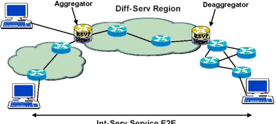
2.1.3 The Aggregate RSVP Protocol . . . 28
2.2 The Overall Framework For QoS Management . . . 33
2.3 Satellite Admission Control . . . 34
2.4 Terrestrial Admission Control . . . 35
2.4.1 The Terrestrial Local Admission in the Scalable CORE (SCORE) Region: Aggregate Reservation Estimation Algorithm . . . 36
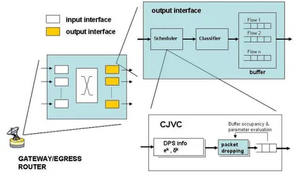
2.4.2 The role of Gateway (GTW) . . . 37
2.4.3 The Distributed Dynamic Packet State (DPS) Approach 40 2.4.4 The Hybrid Egress Router (ER)-DPS Approach . . . 42
2.4.5 The Centralized ER Approach . . . 43
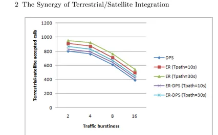
2.5 Performance Evaluation . . . 44
2.6 Conclusions . . . 47
3 Multi-layer Network for Vertical Switching . . . 49
3.1 Wireless HAP segment . . . 49
3.1.1 Traffic Resource Manager (TRM) . . . 51
3.2 Integrated Services on HAP . . . 52
3.3 Integrated Architecture for HAP-Geostatioary Earth Orbit (GEO) Satellite infrastructure . . . 55
3.3.1 Simple Modality Selection . . . 57
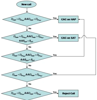
3.3.2 Smart Terminal for automatic selection HAP-Satellite segment . . . 59 3.4 Performance Evaluation . . . 62 3.4.1 Simulation Scenario . . . 62 3.4.2 Simulation Parameters . . . 63 3.4.3 Simulation Results . . . 65 3.5 Conclusions . . . 72
4 Call Admission Control for Multimedia Traffic . . . 75
4.1 Moving Picture Expert Group (MPEG) Standard . . . 75
4.2 MPEG Statistical Modeling . . . 76
4.3 Multimedia Call Admission Control (CAC): Overview . . . 78
4.4 Applicative Scenario . . . 79
4.5 MPEG Traffic Modeling . . . 81
Contents ix
4.6.1 Statistical Multiplexing based on the Normal GOP
Distribution (SMND) . . . 85
4.6.2 Statistical Multiplexing based on Discrete Bandwidth Levels of GOP Rate (SMDB) . . . 87
4.7 Performance Evaluation . . . 91
4.7.1 Simulation Scenario . . . 92
4.7.2 Light Traffic Load . . . 94
4.7.3 Heavy Traffic Load . . . 94
4.8 Conclusions . . . 95
5 Mobile Satellite System: MAC and scheduling design . . . 99
5.1 Current Issue in the mobility support on Satellite . . . 101
5.1.1 Spectrum Spreading in the satellite link . . . 102
5.1.2 Mobile Propagation Channel . . . 103
5.1.3 Handover Management . . . 105
5.1.4 Single Channel Per Carrier (SCPC) on the reverse link . 107 5.2 Current and Future Projects . . . 107
5.3 Description of DVB-RCS System Scenario . . . 110
5.3.1 Return Link Structure . . . 111
5.3.2 Terminal Burst Time Plan (TBTP) . . . 112
5.3.3 Digital Video Broadcasting with Return Channel Satellite (DVB-RCS) Capacity Request Signaling . . . 114
5.3.4 Return Link Dynamic Resource Control . . . 114
5.3.5 Demand Assignment Multiple Access (DAMA) Scheduling Process . . . 115
5.3.6 DVB-RCS Capacity Types . . . 116
5.4 Traffic Models . . . 118
5.4.1 Hyper Text Transfer Protocol (HTTP) Traffic Model . . 118
5.4.2 File Transfer Protocol (FTP) Traffic Model . . . 119
5.4.3 Video Conference Traffic Model . . . 119
5.5 Simulator Environment Description . . . 121
5.5.1 Discrete Event Simulation . . . 121
5.5.2 Measurements . . . 121
5.5.3 Physical Parameters . . . 122
5.6 Threshold Basic Switching Algorithm (TBSA) . . . 123
5.6.1 Moving from MF-TDMA to SCPC . . . 123
5.6.2 Moving from SCPC to MF-TDMA . . . 125
5.7 Simulation Graphic Interface . . . 126
5.8 Simulation Results . . . 126
5.8.1 Simulation on Traffic Generation . . . 128
5.8.2 Simulation results for Scenario 1 . . . 132
5.8.3 Simulation results for Scenario 2 . . . 133
5.8.4 Simulation results for Scenario 3 . . . 135
x Contents
Conclusions . . . 141 References . . . 145 List of Publications . . . 153
List of Figures
1.1 Next Generation Network (NGN) Scenario . . . 3
1.2 Bent Pipe Transponder Satellite . . . 5
1.3 On Board Processor Transponder Satellite . . . 6
1.4 Network Architecture for DVB-RCS . . . 7
1.5 Multi-Layer Network Scenario . . . 11
2.1 Reference Integrated Network Architecture . . . 25
2.2 EuroSkyWay Platform . . . 26
2.3 DPS technique in SCORE architecture . . . 27
2.4 Aggregator - Deaggregator . . . 29
2.5 Example Signalling Flow in an aggregate region . . . 32
2.6 Architecture of Gateway/Egress Router in a SCORE/Satellite Network . . . 38
2.7 Signaling Packets Overhead for different TW values . . . 39
2.8 Satellite Static Efficiency for different TW values . . . 39
2.9 Maximum Delay on GTW for different TW values . . . 40
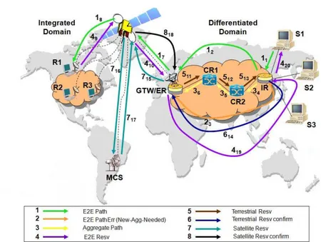
2.10 Message exchange between terrestrial SCORE and InteServ satellite network for DPS . . . 41
2.11 Message exchange between terrestrial SCORE and InteServ satellite network for ER . . . 43
2.12 Burst loss vs. traffic burstiness of terrestrial sources . . . 45
2.13 Number of admitted calls vs. traffic burstiness of terrestrial sources . . . 46
2.14 Number of overhead packets vs. traffic burstiness of terrestrial sources . . . 46
3.1 Integrated HAP-Satellite scenario . . . 50
3.2 Requests queues on TRM module for each ATM class of traffic . 52 3.3 HAP layer architecture . . . 55
xii List of Figures
3.5 Messages exchange for reserving resource on satellite after a HAP failure . . . 58 3.6 DFD of the call admission control in the integrated
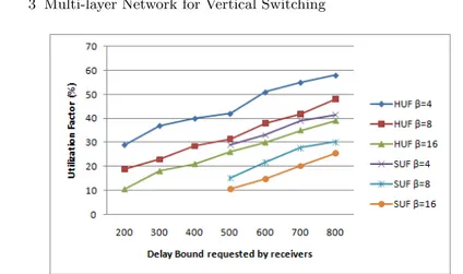
HAP-Satellite network . . . 61 3.7 Block diagram of simulated system . . . 63 3.8 Factor Utilization for HAP (HAP Utilization Factor (HUF))
and Satellite (Satellite Utilization Factor (SUF)) vs. Delay Bound (DB) requested by wireless receivers. The terrestrial
sources have b/r = 2s . . . 66 3.9 Factor Utilization for HAP (HUF) and Satellite (SUF) vs. DB
requested by wireless receivers. The terrestrial sources have
b/r = 8s . . . 66
3.10 Number of Accepted Calls on HAP segment vs. the Delay Bound requested by the wireless receivers. The terrestrial
sources have b/r = 2s . . . 67 3.11 Number of Accepted Calls on HAP segment vs. the Delay
Bound requested by the wireless receivers. The terrestrial
sources have b/r = 8s . . . 68 3.12 Comparison of Satellite Static Efficiency (SSE) for receiver
driven selection (smart selection) and the selection before the HAP and then the satellite segment (first HAP) vs. the
burstiness source traffic . . . 69 3.13 Comparison of Satellite Utilization Factor (SUF) for receiver
driven selection (smart selection) and the selection before the HAP and then the satellite segment (first HAP) vs. the
burstiness source traffic . . . 70 3.14 Comparison of total satellite accepted calls for receiver driven
selection (smart selection) and the selection before the HAP and then the satellite segment (first HAP) vs. the burstiness source traffic . . . 70 3.15 Comparison of total system accepted calls for receiver driven
selection (smart selection) and the selection before the HAP and then the satellite segment (first HAP) vs. the burstiness source traffic . . . 71 3.16 Comparison of the Average End-to-End Delay (AEED)
packet for receiver driven selection between HAP and satellite segments vs. the burstiness source traffic . . . 71 4.1 GOP composition pattern . . . 76 4.2 DVB-RCS Applicative Scenario . . . 80 4.3 Aggregate GOP rate with 1, 2, 3 and 4 traffic sources with 4
discrete bandwidth levels . . . 82 4.4 GOP rate discretization of a specific movie with different
bandwidth levels (2, 4, 6) . . . 83 4.5 Exponential approximation of the state sojourn time . . . 84
List of Figures xiii
4.6 Standard Normal Distribution . . . 87
4.7 Finite State Markov Chain (FSMC) of discrete bandwidth levels associated with the single traffic source . . . 88
4.8 Aggregate states of bandwidth levels of Aggregate GOP rate . . . 89
4.9 Four frames of the considered streams, with the mean and the standard deviation of the GOP-rate . . . 92
4.10 Table of Satellite Utilization (%) in Light Traffic Load (0.6 calls/min) . . . 95
4.11 Table of Average Number of Admitted Calls Light Traffic Load (0.6 calls/min) . . . 95
4.12 Table of GOP Loss Ratio Light Traffic Load (0.6 calls/min) . . . 95
4.13 Table of Satellite Utilization (%) in Heavy Traffic Load (4 calls/min) . . . 96
4.14 Table of Average Number of Admitted Calls in Heavy Traffic Load (4 calls/min) . . . 96
4.15 Table of GOP Loss Ratio in Heavy Traffic Load (4 calls/min) . . 97
5.1 Maximum Numbers of Active Passengers per Country and per Train Type . . . 100
5.2 DVB-RCS Mobile Scenario . . . 101
5.3 Interference scenario . . . 103
5.4 ITU-R Mobile Satellite Services (MSS) Frequency Allocation . . . 103
5.5 NLOS condition in a railway environment . . . 104
5.6 Handover Scenario . . . 105
5.7 Terrestrial Gap Filler Scenario . . . 106
5.8 State diagram for basic continuous carrier operation . . . 107
5.9 State diagram for enhanced continuous carrier operation . . . 108
5.10 Reference Railway Scenario . . . 111
5.11 MF-TDMA Frame Structure . . . 112
5.12 Time diagram of capacity request . . . 115
5.13 HTTP Traffic Model Diagram . . . 119
5.14 Streaming Traffic Model . . . 120
5.15 Turbo Code Performance for PER = 10−7. . . 123
5.16 Performance DVB-RCS+M - 4k . . . 123
5.17 Dynamic switching between DVB-RCS and DVB-S2 zone . . . 124
5.18 Pseudo code for switching from MF-TDMA to SCPC mode . . . . 124
5.19 Example of capacity request control performed by the TBSA algorithm . . . 125
5.20 Pseudo code for switching from SCPC to MF-TDMA mode . . . . 125
5.21 Example of throughput control performed by NCC to switch from SCPC to MF-TDMA . . . 126
5.22 Initial screen of the simulation graphic interface . . . 127
5.23 Satellite scenario configuration . . . 127
5.24 HTTP capacity request for a small number of users . . . 129
xiv List of Figures
5.26 FTP capacity request for a small number of users . . . 130 5.27 FTP capacity request for a great number of users . . . 130 5.28 Video Conference capacity request for a small number of users . 131 5.29 Video Conference capacity request for a great number of users . 131 5.30 RBDC delay varying the capacity repartition between
MF-TDMA and SCPC . . . 132 5.31 VBDC delay varying the capacity repartition between
MF-TDMA and SCPC . . . 133 5.32 RBDC queue size varying the capacity repartition between
MF-TDMA and SCPC . . . 133 5.33 VBDC queue size varying the capacity repartition between
MF-TDMA and SCPC . . . 134 5.34 RBDC delay comparison between classical MF-TDMA system
and a system with a 90% of MF-TDMA and 10% of SCPC
and the TBSA algorithm . . . 134 5.35 VBDC delay comparison between classical MF-TDMA system
and a system with a 90% of MF-TDMA and 10% of SCPC
and the TBSA algorithm . . . 135 5.36 RBDC queue size comparison between classical MF-TDMA
system and a system with a 90% of MF-TDMA and 10% of SCPC and the TBSA algorithm . . . 135 5.37 VBDC queue size comparison between classical MF-TDMA
system and a system with a 90% of MF-TDMA and 10% of SCPC and the TBSA algorithm . . . 136 5.38 Number of switching in the system in order to move from a
modality to the other one . . . 136 5.39 RBDC delay varying the capacity repartition between
MF-TDMA and SCPC . . . 137 5.40 Number of switching for scenario 2 . . . 137 5.41 RBDC delay varying the capacity repartition between
MF-TDMA and SCPC . . . 138 5.42 Number of switching for scenario 3 . . . 138
List of Tables
2.1 Simulation Parameters . . . 44
3.1 Simulation Parameters for Satellite Segment . . . 62
3.2 Simulation Parameters for HAP Segment . . . 62
3.3 Simulation Parameters . . . 64
4.1 Markov Chain Parameters for 4 Movies (3 State Approximation) 93 4.2 DVB-RCS Simulation Parameters . . . 93
4.3 Simulated Scenario . . . 94
Acronyms
ACQ ACQuisition Burst
ADSL Asymmetric Digital Subscriber Line AEED Average End-to-End Delay
AF Assured Forwarding AR Auto-Regressive
ARSVP Aggregate Resource ReSerVation Protocol
ARTES Advanced Research in Telecommunications Systems - Multimedia Programme
ATM Asynchronous Transfer Mode
AVBDC Absolute Volume Based Dynamic Capacity AWGN Additive White Gaussian Noise
BB Base-Band BE Best Effort
BEF Bandwidth Expansion Factor BER Bit Error Rate
BoD Bandwidth on Demand BP Bent Pipe
bps bit per second
BPSK Binary Phase Shift Keying C/N Carrier-to-Noise
C2P Connection Control Protocol CAC Call Admission Control CBR Constant Bit Rate
CDMA Code Division Multiple Access
CDTI Centro para el Desarrollo Tecnolgico Industrial CJVC Core Jitter Virtual Clock
CLS Controlled Load Service
CMF Control and Monitoring Functions CoS Class of Service
xviii Acronyms
CR Core Router
CRA Continuous Rate Assignment CSC Common Signaling Channel burst DAMA Demand Assignment Multiple Access dB decibel
DB Delay Bound
DBS Direct Broadcast Satellite
DBS-RCS Direct Broadcast Satellite with Return Channel Satellite DES Discrete Event Simulation
DFD Data Flow Diagram DiffServ Differentiated Services
DLR Deutsches Zentrum fr Luft- und Raumfahrt DoD Department of Defense
DPS Dynamic Packet State
DSCP Differentiated Services Code Point DTH Direct-To-Home
DULM Data Unit Labeling Method DVB Digital Video Broadcast
DVB-RCS Digital Video Broadcasting with Return Channel Satellite DVB-RCS+M Digital Video Broadcasting with Return Channel Satellite +
Mobile
DVB-S Digital Video Broadcasting Satellite
DVB-S2 Digital Video Broadcasting Satellite - second generation DVD Digital Versatile Disc
E2E End-to-End
EDP Excess Demand Probability EF Expedited Forwarding
EIRP Equivalent Isotropically Radiated Power ER Egress Router
ESA European Space Agency
ESTEC European Space Research and Technology Centre ESW EuroSkyWay
ETSI European Telecommunications Standards Institute F/G Feeder/Gateway
FCA Free Capacity Assignment
FCC Federal Communications Commission FDMA Frequency Division Multiple Access fec forwarding equivalence class
FEC Forward Error Correction
FIFTH Fast Internet for Fast Train Hosts fps frame per second
Acronyms xix
FS Fixed Service
FSS Fixed Satellite Service FTP File Transfer Protocol GEO Geostatioary Earth Orbit GLR GOP Loss Ratio
GMBS Global Mobile Broadband System GOP Group of Picture
GS Guaranteed Service GSO Geosynchronous GTW Gateway
G-VBDC Guaranteed VBDC HAP High Altitude Platform HCAC HAP Call Admission Control HCC HAP Connection Control HGTW HAP Gateway Station HMCS HAP Master Control Station HNOC HAP Network Operation Center HPA High Power Amplifier
HP-VBDC High Priority VBDC
HRRM HAP Radio Resource Management HSE HAP Static Efficiency
HTML Hyper Text Mark-Up Language HTRM HAP Traffic Resource Manager HTTP Hyper Text Transfer Protocol HUF HAP Utilization Factor
IAT Inter-Arrival-Time IBR In Band Request IntServ Integrated Services
IEC International Electrotechnical Commission IETF Internet Engineering Task Force
IHL Inter-HAP Link
i.i.d. independent and identically-distributed IOL Inter Orbit Link
IPN InterPlaNetary
IPTV Internet Protocol TeleVision IR Ingress Router
ISDN Integrated Services Digital Network ISI InterSymbol Interference
ISO International Organization for Standardization ISP Internet Services Provider
IT Information Technology
xx Acronyms
ITU-R International Communication Union - Radiocommunication Sector IWF Inter Working Functions
JVC Jitter Virtual Clock kbps kilo bit per seconds ksps kilo symbol per seconds
LDA Loss-Delay-based Adaptation Algorithm LEO Low Earth Orbit
LER Label Edge Router LNA Low Noise Amplifier LoS Line of Sight
LRD Long Range Dependent LSP Label Switched Path LSR Label Switching Router
MAB Maximum Available Bandwidth MAC Medium Access Control
Mbps Mega bit per seconds MCS Master Control Station
MF-TDMA Multi-Frequency Time Division Multiple Access MHUT Mobile HAP User Terminal
MOWGLY Mobile Wideband Global Link sYstem MPEG Moving Picture Expert Group
MPEG-TS MPEG - Transport Stream MPEG2-TS MPEG2 - Transport Stream MPL Minimum Path Latency
MPLS Multi Protocol Label Switching MSS Mobile Satellite Service
NCC Network Control Center NGN Next Generation Network NGSO Non-Geosynchronous NLoS Non Line of Sight
NOAC Number of Overall Admitted Calls NoAd Non Adaptive
NOC Network Operator Center nRT non Real Time
nrt-VBR Non-Real Time Variable Bit Rate OBP On-Board Processor
OBR Out Band Request PD Propagation Delay
Acronyms xxi
PER Packet Error Rate PHB Per Hop Behavior
PSTN Public Switched Telephone Network QD Queuing Delay
QOAS Quality Oriented Adaptation Scheme QoS Quality of Services
QPSK Quadrature Phase Shift Keying RBDC Rate Based Dynamic Capacity RCS Return Channel Satellite
RCST Return Channel Satellite Terminal RF Radio Frequency
RL Return Link
RRM Radio Resource Management RSVP Resource reSerVation Protocol RT Real Time
RTT Round Trip Time
rt-VBR Real Time Variable Bit Rate SAC Satellite Access Control
SaT Satellite User Terminal
SBBP Switched Batch Bernoulli Process SCAC Satellite Call Admission Control SCORE Scalable CORE
SCPC Single Channel Per Carrier SDR Software Defined Radio SGTW Satellite Gateway SI Signaling Information SLA Service Level Agreement
SMCS Satellite Master Control Station
SMDB Statistical Multiplexing based on Discrete Bandwidth Levels of GOP Rate
SMND Statistical Multiplexing based on the Normal GOP Distribution SR Static Rate
SRD Short Range Dependence SSE Satellite Static Efficiency ST Satellite Terminal
SUF Satellite Utilization Factor SYNC SYNChronization
TBSA Threshold Basic Switching Algorithm TBTP Terminal Burst Time Plan
TCP Transport Control Protocol TDMA Time Division Multiple Access
xxii Acronyms
TFRCP TCP Friendly Rate Control Protocol TIM Terminal Information Message
TM-RCS Technical Module - Return Channel Satellite TOS Type-of-Service
TRF TRaFfic burst
TRM Traffic Resource Manager UL UpLink
UMTS Universal Mobile Telecommunications System VBDC Volume Based Dynamic Capacity
VBR Variable Bit Rate VHS Video Home System VoD Video on Demand VoIP Voice over IP
VPN Virtual Private Network VR Virtual Reality
VSAT Very Small Aperture Terminal WiFi Wireless Fidelity
1
Next Generation Network (NGN) - State of
the Art
As demands on the network continue to grow, it is increasingly important to upgrade the existing infrastructure in order to offer higher bandwidth and service level guarantees to the users.
The Next Generation Network (NGN) is designed to be all IP-based sup-porting heterogeneous core and access technologies for broadband and mobile applications. Fixed, as well as, mobile satellite systems will be fully integrated with future wireless and wired networks.
The general definition of International Communication Union (ITU) pro-vided for NGN in [1] is: “A packet-based network able to provide telecom-munication services and able to make use of multiple broadband, Quality of Services (QoS)-enabled transport technologies and in which service-related functions are independent from underlying transport related technologies. It enables free access for users to networks and to competing service providers and/or services of their choice. It supports generalized mobility which will allow consistent and ubiquitous provision of services to users.”
1.1 Global Communication Network Scenario
The future generation of communication networks provides “multimedia ser-vice”, “wireless (cellular and satellite) access to broadband networks” and “seamless roaming among different system”.
The term NGN is commonly used to give a name to the changes to the service provision infrastructures that have already started in the telecommu-nication and Information Technology (IT) industry. A NGN is a packet-based network able to provide services including Telecommunication Services. It of-fers unrestricted access by users to different service providers. It supports generalized mobility which will allow consistent and ubiquitous provision of services to users. The NGN is characterized by the following fundamental aspects [2]:
2 1 Next Generation Network (NGN) - State of the Art
- Packet-based transfer;
- Separation of control functions among bearer capabilities, call/session, and application/ service;
- Decoupling of service provision from network, and provision of open inter-faces;
- Support for a wide range of services, applications and mechanisms based on service building blocks (including real time/ streaming/ non-real time services and multi-media);
- Broadband capabilities with end-to-end QoS and transparency; - Unrestricted access by users to different service providers; - Converged services between Fixed/Mobile network;
- Independence of service-related functions from underlying transport tech-nologies;
- Compliant with all Regulatory requirements, for example concerning emer-gency communications and security/privacy, etc;
In this context, the integration of heterogeneous networks that have the task of providing full access and total coverage to the users that, nowadays, exchange a lot of information whenever and wherever takes place. A possible scenario of a NGN is depicted in Fig. 1.1. A main role in networks cooperation is played by the wireless networks that are capable of reaching users in places where the normal terrestrial infrastructures do not have the possibility. Other the well-known satellite architecture there is another wireless platform that is acquiring a lot of importance in telecommunications, called High Altitude Platform (HAP). The main advantage of these types of architectures is the possibility of offering ubiquitous coverage, bandwidth flexibility, multipoint-multipoint connectivity and fast service initiation after deployment and reli-ability.
1.2 Satellite Networks
Satellite systems have been an important element of telecommunications net-works for many years serving, in particular, long distance telephony and tele-vision broadcasting. The involvement of satellite in IP networks is a direct result of new trends in global telecommunications where Internet traffic will hold a dominant share in the total network traffic. The large geographical cov-erage of the satellite footprint and its unique broadcasting capabilities as well as its high-capacity channel combined with readily available Ka-band spec-trum will retain satellite systems as an irreplaceable part of communications systems, despite its high cost and its long development and launching cycle. Traditionally, satellite communication systems have played a significant role in supporting services such as TV broadcasting, digital messaging, enterprise Virtual Private Network (VPN) and point-to-point telecommunications and data services.
1.2 Satellite Networks 3
Fig. 1.1. Next Generation Network (NGN) Scenario
The recent Internet growth has resulted in a new generation of appli-cations with higher throughput requirements and communication demands. Service, Network and Internet access providers are faced with a challenge to meet the higher capacity access to the end user and wider service offerings. Satellite network systems can be optimized to meet new service demands such as aeronautical and mobile applications. For example, trade-off studies of the frequency of operation, (Ku, Ka), processing versus nonprocessing payload, switching (IP, MPLS), QoS mechanisms, type of antennas, network protocols, transport protocols, crosslayer designs, network management, techniques have to be performed to meet the driving applications and requirements [3].
Several broadband satellite networks at Ka-band are planned and being developed to provide such global connectivity for both Fixed Satellite Service (FSS) and Mobile Satellite Service (MSS), using Geosynchronous (GSO) and Non-Geosynchronous (NGSO) satellites. Currently, GSO satellite networks with Very Small Aperture Terminal (VSAT) at Ku-bands are being used for several credit card verifications, rental cars and banking applications.
At that time, Ka-band satellite communications systems became so pop-ular because they could provide:
- Large bandwidth: the large amount of bandwidth availability in Ka-bands is the primary motivation for developing Ka-band satellite systems since lower frequency bands have become congested;
- Small antenna size: as the frequency goes up, the size of the antenna will decrease for a given gain and beamwidth. For a fixed antenna size, this
4 1 Next Generation Network (NGN) - State of the Art
will significantly reduce the interference from adjacent satellite systems. Obviously, the price of the smaller antenna will be lower, which makes broadband satellite service affordable to millions of commercial and resi-dential end-users;
- Larger system capacity: Ka-band satellites provide smaller spot-beams to increase the satellite power density and allow large frequency reuses, which will lead to higher spectrum occupancy. Many user terminals can be served simultaneously;
- Ubiquitous access: services are available at any location within the satel-lite footprint, especially in locations where terrestrial wired network are impossible or economically unfeasible;
- Flexible bandwidth-on-demand capability: this feature maximizes the band-width and resource utilization and minimizes the cost to end-users. On the other hand, Ka-band satellite links suffer degradation due to at-mospheric propagation effects, which are more severe at the Ka-band than the degradation that happens at lower frequency bands. The primary prop-agation factors are rain attenuation, wet antenna losses, depolarization due to rain and ice, gaseous absorption, cloud attenuation, atmospheric noise and tropospheric scintillation. Among those factors, rain attenuation is the most challenging obstacle to Ka-band systems [4]
1.3 Satellite Communication Fundamentals
There are two basic types of transponders, Bent Pipe (BP) and On-Board Processor (OBP). The early satellite transponders were based on analog trans-mission, but most modern satellite systems deliver signals digitally to ensure reliability and accuracy in information transmission. Digital switching tech-niques in OBP have facilitated a large scale deployment of affordable satellite-terrestrial networks.
1.3.1 Transparent Satellite System
The BP transponder acts as a transparent repeater. It consists of receiving and transmitting antennas, a Low Noise Amplifier (LNA) receiver, a frequency converter and a High Power Amplifier (HPA). The earth station transmitter will deliver signals to the satellite receiver. The uplink signals will be received at the receiving antenna, down converted, fed to the HPA and then transmit-ted down to the receiving earth station via the transmitting antenna. Usually, no change is made to the signal except an amplification to overcome the large path losses and a frequency conversion to separate the up and down links. Generally, the transponder is transparent to the users since the transmitting signal from one earth station will ’bounce’ and arrive to another earth station with its characteristics unchanged.
1.3 Satellite Communication Fundamentals 5
Figure 1.2 shows the basic BP satellite link. The conventional way of char-acterizing the satellite link behavior using BP transponders is to use Carrier-to-Noise (C/N). The C/N ratio represents the decibel (dB) difference between the desired carrier signal power and the undesired noise power at the receiver. It also indicates the received signal quality for both analog and digital trans-missions. In satellite communications systems the C/N calculation is often called a power link budget.
Fig. 1.2. Bent Pipe Transponder Satellite
1.3.2 Intelligent Satellite System
The conventional BP satellite delivers signals on the same route; from the receiver to the transmitter, all signals on that specific transponder will usually be together, coming from the same transmitting earth station and going to the same receiving earth station. This limits the flexibility of the satellite network application.
The OBP satellite system, consisting of regenerative transponders and on-board switching with multiple spot-beams, provides bandwidth on demand with low processing delay, flexible inter-connectivity and lowered ground sta-tion costs. In an OBP satellite system, both the uplink and the downlink of the OBP system are independent to each other. The uplink signals with distortions or noise reaching the space station receiver are down-converted, demodulated, de-multiplexed and reconstructed. The reconstructed signals are then modulated, multiplexed and up-converted to be transmitted at the downlink. Thus, the uplink degradation will have no effect on the downlink transmission. This process, called Base-Band (BB) processing, significantly improves the overall link performance at the receiving earth station.
6 1 Next Generation Network (NGN) - State of the Art
Figure 1.3 shows the basic OBP system architecture and its links. Because demodulation is digitally applied in the regenerative transponder, it is neces-sary to represent the C/N ratio in terms of Bit Error Rate (BER). BER used in digital signals is to measure the probability of bit error that will occur in a given amount of time in the system.
Fig. 1.3. On Board Processor Transponder Satellite
1.3.3 Satellite Link Multiple Access Techniques
Since large amounts of bandwidth are available on Geostatioary Earth Orbit (GEO) Ka-band satellites, an appropriate bandwidth management technique is necessary. One of the best ways is to use a multiple access technique. In satellite communications systems, multiple access allows many earth stations to share a transponder even thought their carriers have different signal char-acteristics.
Three common types of multiple access deployed in satellite communica-tions systems are Frequency Division Multiple Access (FDMA), Time Divi-sion Multiple Access (TDMA) and Code DiviDivi-sion Multiple Access (CDMA). A common hybrid solution is used by combining techniques such as FDMA / TDMA well-known in literature as Multi-Frequency Time Division Multiple Access (MF-TDMA).
1.4 Digital Video Broadcasting with Return Channel
Satellite (DVB-RCS) Architecture
DVB-RCS [5], [6] is a technical standard, designed by the Digital Video Broadcast (DVB) Project, that defines a complete air interface specification
1.4 Digital Video Broadcasting with Return Channel Satellite (DVB-RCS) Architecture 7
for two-way satellite broadband VSAT systems. Low cost VSAT equipment can provide highly dynamic demand-assigned transmission capacity to resi-dential and commercial/institutional users (see Fig. 1.4).
Fig. 1.4. Network Architecture for DVB-RCS
DVB-RCS provides users with the equivalent of an Asymmetric Digital Subscriber Line (ADSL) or cable Internet connection, without the need for local terrestrial infrastructure. Depending on satellite link budgets and other system design parameters, DVB-RCS implementations can dynamically pro-vide anywhere up to 20 Mega bit per seconds (Mbps) to each terminal on the outbound link and up to 5 Mbps or more from each terminal on the inbound link. The standard is published by European Telecommunications Standards Institute (ETSI) as EN 301 790 [5].
DVB’s Technical Module - Return Channel Satellite (TM-RCS) has now approved the Digital Video Broadcasting with Return Channel Satellite + Mobile (DVB-RCS+M) specification [7], providing support for mobile and no-madic terminals as well as enhanced support for direct terminal-to-terminal (mesh) connectivity. DVB-RCS+M includes features such as live handovers between satellite spot-beams, spread-spectrum features to meet regulatory constraints for mobile terminals, and continuous-carrier transmission for ter-minals with high traffic aggregation. It also includes link-layer Forward Error Correction (FEC) based on Raptor or Reed-Solomon codes, used as a coun-termeasure against shadowing and blocking of the satellite link [8].
Today there are several vendors of DVB-RCS standard compliant systems as well as proprietary VSAT systems that provide services of the same gen-eral nature as DVB-RCS, but without full compliance with the standard. DVB-RCS was developed in response to a request from several satellite and
8 1 Next Generation Network (NGN) - State of the Art
network operators who wanted to embark on large-scale deployment of such systems considering it essential to have an open standard in order to mit-igate the risks associated with being tied to a single vendor. The standard was developed using state-of-the-art techniques, allowing an optimized trade-off between performance and cost. As a consensus based standard DVB-RCS also has a controlled evolutionary future, secured by global contributions to the system under an agreed and open framework.
1.4.1 How does it works
In its basic form, DVB-RCS provides hub-spoke connectivity; i.e., all user ter-minals are connected to a central hub that both controls the system and acts as a traffic gateway between the users and the wider Internet. User termi-nal consists of a small indoor unit and an outdoor unit with an antenna size not much bigger than a conventional direct-to-home TV receiver. Since the DVB-RCS terminal also transmits data, the outdoor unit includes a Radio Frequency (RF) power amplifier.
The user terminal offers an Ethernet that can be used for wired or wireless interactive IP connectivity for a local home or office network ranging from one to several users. In addition to providing interactive DVB services and Internet Protocol TeleVision (IPTV), DVB-RCS systems can thus provide full IP connectivity anywhere there is suitable satellite coverage, which in turn means most places on the earth including areas not covered by other solutions.
The core of DVB-RCS is a MF-TDMA transmission scheme for the re-turn link, which provides high bandwidth efficiency for multiple users. The demand-assignment scheme uses several capacity mechanisms that allow op-timization for different classes of applications, so that voice, video streaming, file transfers and web browsing can all be handled efficiently. DVB-RCS sup-ports several access schemes making the system much more responsive and thus more efficient than traditional demand-assigned satellite systems.
These access schemes are combined with a flexible transmission scheme that includes state-of-the-art turbo coding, several burst size options and ef-ficient IP encapsulation options. These tools allow systems to be fine-tuned for the best use of the power and bandwidth satellite resources.
The forward link is shared among a population of terminals using either Digital Video Broadcasting Satellite (DVB-S) (EN 300 421) [9] or the highly efficient Digital Video Broadcasting Satellite - second generation (DVB-S2) standard (EN 302 307) [10]. Adaptive transmission, to overcome variations in channel characteristics (e.g., rain fade), can be implemented in both the forward and return links. Beyond the basic hub-and-spoke architecture, the DVB-RCS air interface has also been deployed in systems that provide di-rect terminal-to-terminal mesh connectivity, either through satellite on-board processors that mirror the functions of a ground-based hub, or through trans-parent satellites, using terminals equipped with an additional demodulator.
1.5 High Altitude Platform (HAP) Networks 9
1.4.2 Next Steps for DVB-RCS
DVB-RCS was first published in 2000 and it has been relatively stable. Until the introduction of DVB-RCS+M, changes have mainly been for maintenance, such as inclusion of support for the DVB-S2 forward link standard.
DVB-RCS+M is the first major revision of the standard. Although no fur-ther revisions are currently in progress, the DVB-RCS community is continu-ously assessing the commercial needs of the users, to ensure that the standard will continue to meet their objectives in the most efficient way. Successful trials and implementations have already been carried out using terminals mounted in trains, maritime vessels and aircrafts. This is being paralleled by the ad-dition of sophisticated mobility support features to DVB-RCS. These include live handovers between satellite spot-beams, spread spectrum features to meet regulatory constraints for mobile terminals and countermeasures against shad-owing and blocking of satellite link.
1.5 High Altitude Platform (HAP) Networks
HAP is a new technology of airships or planes that will operate in the strato-sphere at an altitude of 17-22 km above the ground. The high potentialities of these network elements have captured the interest of academic and industrial environments in recent years. They have the potential capability to be quickly deployed and they do not need a complex infrastructure, as for the terrestrial network [11], [12].
Recently, the ITU has licensed several frequency bands for communica-tions in HAP: 2GHz, 30 GHz, 48GHz, and mm-wave bands. These different frequency bands lead to the necessity of studying the characteristics of the physical medium and of the coding techniques in order to have an idea of the potentialities offered for new kinds of services in terms of allowable data rate, bit error rate and energy consumption. An important aspect is to understand and define which kind of antennas are suitable for this new network segment and which kind of terminals can be used in order to use new potentialities and to offer new services [13].
Many studies have been conducted in order to propose integration with the Terrestrial - Universal Mobile Telecommunications System (UMTS) network in order to reach inter-operability with the existent infrastructure; in addition, studies have been proposed considering the HAP segment as an access segment able to provide broadband and narrow-band services.
All these studies lead to a key question about the future of this technol-ogy: can the HAP be seen as a complementary technology or a disruptive technology? In the vision of this thesis, the HAP segment will represent, in areas without terrestrial infrastructure, a winning technology able to provide connection services and multimedia services. Further, it will represent in area
10 1 Next Generation Network (NGN) - State of the Art
with wired infrastructure an additional network element able to provide sev-eral benefits for new classes of users and services.
Also, if satellite networks, and in particular the GEO satellite networks, have become important in these last few years, the HAP layer will offer an-other complementary element able to reduce problems regarding the signal attenuation, the power of terminal and base station and the long propagation delay (GEO satellite presents high end-to-end delay).
In this context, it is important to consider the new role played by the HAP segment and to consider the potential integration of this new element with the existing networks. In particular, it is interesting to analyze the possible integration of HAP with the existing satellite network in order to obtain an efficient management and coexistence of the two networks. It is possible to use the satellite segment for services that do not need specific delay restrictions and HAP (when the segment is deployed) to give access to users that need particular delay-sensitive services.
1.6 Multi-layer Networks
The integration between different and heterogeneous networks leads to the realization of a hierarchical network scenarios, in which it is possible to see the inter-operation of more than one kind of networks [14]. A general hierarchical scenario is composed of a satellite that, with its spot beam, covers a great part of territory, i.e. a continent.
In this spot beam a certain number of HAP platforms are included, forming a constellation with a coverage area smaller than satellite one. At last, it is possible to find wireless access points or wired routers that permit to different users the network connection. This is a possible scenario that includes different network elements in order to be able to offer the maximal connectivity. An example of a heterogeneous, hierarchical, multi-layer scenario is depicted in Fig. 1.5.
It is easy to understand that satellite networks are irreplaceable for per-sonal communications, for example in wide areas or in the case of disasters such as earthquakes, tsunamis, hurricanes or terrorist activities. In the ab-sence of a wired infrastructure, any individual host or an ad hoc network can access the rest of the wired network through satellites. The advantages of a multi-layer satellite architecture are: a) scalability; b) low delay for real-time traffic; c) flexibility for personal communications.
1.7 Quality of Services (QoS) Issues over Next
Generation Network (NGN)
Near real-time data communications (e.g. World Wide Web (WWW) brows-ing) has already demonstrated that the Internet and the underlying gener-ation of packet network technologies, which operate on the basis of ‘Best
1.7 Quality of Services (QoS) Issues over Next Generation Network (NGN) 11
Fig. 1.5. Multi-Layer Network Scenario
Effort (BE)’, provide insufficient QoS support. In the NGNs, packet network technologies will have to provide real-time services (voice, multimedia) and a improved QoS support. Packet based transport technologies will thus have to include advanced QoS management capabilities such as:
- QoS aware network equipment (Resource reSerVation Protocol (RSVP), In-tegrated Services (IntServ), Differentiated Services (DiffServ), Multi Pro-tocol Label Switching (MPLS));
- Admission control mechanisms;
- Interaction between call signalling, resources management and admission control.
As far as satellite based systems are concerned, especially those including sophisticated resource management features in order to use a shared access such as DVB-RCS, no architecture or mechanisms have been defined or recom-mended by standardization bodies. The provision of an end-to-end QoS based service with a satellite access is thus largely undefined and will eventually lead to system specific or proprietary solutions.
Such recommendations exist in the field of cable access and mobile access networks. Their absence in the satellite field may lead to slow down the up-taking of NGN and their associated services by satellite. Moreover, due to the characteristics of those services, many of them being of real-time nature and to the specificity of geostationary DVB-RCS based satellite access systems (delay, multiple access), QoS aspects need to be analyzed specifically.
12 1 Next Generation Network (NGN) - State of the Art
The real-time nature of interpersonal communication services poses NGNs significant challenges in terms of resource management. Typically, these ser-vices require resources to be made available on demand and expect the request to be answered almost instantly (it is unlikely that users will tolerate lengthy call set up times given their experience of todays telephony services), their QoS requirements tend to be fairly stringent and they need to be maintained for the duration of the call.
Since QoS-aware services and applications rely heavily on signalling for their operation it is important to consider the resource requirements of the signalling traffic itself. An obvious consideration is the additional bandwidth that will be consumed by the signalling traffic. Although it should still remain small compared to the user traffic, it is likely to become significant enough and should not be overlooked.
Perhaps, more important are the end-to-end delay and packet loss experi-enced by signalling traffic. Some services, particularly those with a real-time component, will require an almost trouble-free signalling channel for success-ful operation. Any problems experienced by the signalling traffic are likely to lead to degraded service performance, if not a complete service failure. Other services will be more tolerant and have less demanding targets for their associated signalling.
QoS mechanisms provide service differentiation and performance measures for Internet applications according to their requirements. Performance assur-ance addresses bandwidth, loss, delay and delay variation. Bandwidth is a fundamental resource for satellite communication and its proper allocation determines the system throughput. End-to-end delay is also important for several applications.
There are choices to provide the Internet QoS. These are IntServ [15], DiffServ [16] and MPLS [17]. However, the research of application of these QoS framework to broadband satellite network requires supporting IP QoS in a dynamic demand assignment capability environment. A workable QoS architecture must provide a means for specifying performance objectives for different types of packets, as well as, a means of delivering those performance objectives.
To give different packets different treatment, the network infrastructure must be capable of distinguishing between packets by means of classification, queuing packets separately as a result of the classification, scheduling packet queues to implement the differential treatments, providing means for mea-suring, monitoring, and conditioning packet streams to meet requirements of different QoS levels. These can be realized through the implementations of mechanisms in the packet-forwarding path. The number of ways in which a packet can be treated in the forwarding path is limited.
Aggregating individual flows according to their common packet forward-ing treatment leads to a reduction of state and complexity. QoS requires the cooperation of all network layers from top-to-bottom, as well as, every net-work element from end-to-end. At each layer, using efficient technologies and
1.9 QoS Architecture 13
counteracting any factors causing degradation achieve the user performance requirements. For example, at the physical layer, bandwidth efficient modu-lation and encoding schemes, such as concatenated coding and adaptive cod-ing, have to be used to improve the BER and power level performance under whether conditions such e.g. rain.
Similarly, a superior QoS is achieved providing the guaranteed bandwidth at the link layer by using efficient bandwidth on demand multiple access schemes and studying the interaction of bandwidth allocation mechanisms in the presence of congestion and fading. The provision of a specific bandwidth to be offered by the physical layers to the upper layers implies the existence of a bandwidth allocation scheme that shares the bandwidth available among the different user terminals with different traffic classes.
To satisfy the different QoS service level guarantees according to Service Level Agreement (SLA)s with DiffServ at the network layer, service classifi-cation, marking, queuing, and scheduling functions can be used. Currently, most of the Internet applications use the Transport Control Protocol (TCP) and several TCP enhancements exist for satellite environment mitigating the link impairments. Eventually, these QoS parameters have to be mapped to the application QoS as required by the system design and target applications.
1.8 QoS Parameters
The QoS parameters, which can be used in order to satisfy the constraints impose by the users, are:
- Delay: the time for a packet to be transported from the sender to the re-ceiver;
- Jitter: the variation in end-to-end transit delay;
- Bandwidth: the maximal data transfer rate that can be sustained between two end points;
- Packet Loss: defined as the ratio of the number of undelivered packets to the total number of sent packets;
- Reliability: the percentage of network availability depending upon the var-ious environmental parameters such as rain.
To achieve an end-to-end QoS in both satellite and/or hybrid satel-lite/terrestrial networks is a non-trivial problem. However, end-to-end QoS objectives, including security, need considerable research. A successful end-to-end QoS model depends upon the various interfaces at each subsequent lower layer to the upper layers.
1.9 QoS Architecture
There are several mechanisms for QoS provisioning. These are IntServ [15], DiffServ [16] and MPLS [17].
14 1 Next Generation Network (NGN) - State of the Art
1.9.1 Integrated Services (IntServ) Architecture
The IntServ architecture assumes that explicit setup mechanisms are em-ployed to convey information to the routers involved in a source-to-destination path. These mechanisms enable each flow to request a specific QoS level. The classes of service offered by IntServ are Guaranteed Service (GS) [18], which specifies quantitative constraints in terms of maximum end-to-end data delay and Controlled Load Service (CLS) [19], expressing qualitative QoS require-ments.
RSVP [20], [21], [22] is the most widely used set-up mechanism enabling the resource reservation over a specific path from source to destination. Through RSVP signaling, network elements are notified of “per-flow” resource require-ments using IntServ parameters (e.g. token bucket depth b, token generation rate r, peak data rate p, etc.). Subsequently, such networks elements apply ad-mission control and traffic resource management policies to ensure that each admitted flow receives the requested services.
The main drawback of RSVP, which limits its deployment in full services IP networks, is due to the use of per-flow state and per-flow processing which raise scalability problem for large networks. On the other hand, RSVP permits a fine control of bandwidth because it storages per-flow state in the routers [23].
Guaranteed Service (GS)
Guaranteed Service (GS) [18] provides quantitative guarantee on a certain data flow. It is capable of respecting an assured level of bandwidth and a precise end-to-end delay bound.
This Class of Service (CoS) can manage applications with stringent real-time delivery requirements, such as certain audio and video applications. Each router characterizes the GS for a specific flow by allocating a bandwidth R and buffer space B. This is done by approximating the fluid model of service [20] so that the flow effectively sees a dedicated wire of bandwidth R between source and receiver.
In a perfect fluid model, a flow conforming to a token bucket of rate r and depth b will have its delay bound by b \ R provided R >= r. To allow for deviations from this perfect fluid model in the routers approximation, two error terms, C and D, are introduced [20]; consequently, the delay bound now becomes b \ R + C \ R + D. However, with GS a limit is imposed on the peak rate p, of the flow, which results in a reduction of the delay bound.
In addition, the packetization effect of the flow needs to be taken into account by considering the maximum packet size M . These additional factors result in a more precise bound on the end-to-end queuing delay as follows:
Qdelayend2end=(b − M )(p − R)
R · (p − R) +
(M + Ctot)
1.9 QoS Architecture 15
Qdelayend2end=(M + Ctot)
R + Dtot if R ≥ p ≥ r (1.2)
where Ctotand Dtotrepresent the summation of the C and D error terms,
respectively, for each router along the end-to-end data path. In order for a router to invoke guaranteed service for a specific data flow, it needs to be informed of the traffic characteristics Tspec of the flow along with the reser-vation characteristics Rspec. The p, r, b, M values are the Tspec parameters of the IntServ model.
Controlled Load Service (CLS)
Under the CLS [19] model the packets of a given flow will experience delays and loss comparable to a network with no load, always assuming compliance with the traffic contract. CLS provides approximately the same quality of service under heavy loads as under light loads.
A description of the traffic characteristics for the flow desiring CLS must be submitted to the router as for the case of GS although it is not necessary to include the peak rate parameter. If the flow is accepted for CLS then the router makes a commitment to offer the flow a service equivalent to that seen by a best-effort flow on a lightly loaded network. The important difference from the traditional Internet best-effort service is that the CLS flow does not noticeably deteriorate as the network load increases.
By contrast, a best-effort flow would experience progressively worse service (higher delay and loss) as the network load is increased. The CLS is intended for those classes of applications that can tolerate a certain amount of loss and delay provided it is kept to a reasonable level. Examples of applications in this category include adaptive real-time applications.
CLS has some fairly simple implementations, in terms of the queuing sys-tems in routers. It also works adequately for the existing Mbone applications, which can adapt to the modest (small) scale end-to-end delay, variations and jitter that it may introduce, through the use of adaptive playout buffering. It is not suited to applications that require very low latency (e.g. distributed Virtual Reality (VR) systems and so forth). These applications may assume that:
- A very high percentage of transmitted data packets will be successfully delivered by the network to the receiving hosts.
- The data packets will experience little or nothing average packet queuing delay
To ensure that these conditions are met, clients requesting CLS provide the intermediate network elements with a estimation of the data traffic they will generate: the TSpec.
16 1 Next Generation Network (NGN) - State of the Art
1.9.2 Resource reSerVation Protocol (RSVP)
The Resource reSerVation Protocol (RSVP) is the most widely used set-up mechanism enabling the resource reservation over a specific path from source to destination. It, fundamentally, uses two message types in order to exchange signalling between terminals that want to start a communication respecting QoS requirements. These messages are Resv and Path.
An elementary RSVP reservation request consists of a “flowspec” together with a “filter spec”; this pair is called a “flow descriptor”. The flowspec speci-fies a desired QoS. The filter spec, together with a session specification, defines the set of data packets (the “flow”) to receive the QoS defined by the flowspec. A Path message contains the following information in addition to the previous hop address: Sender Template, Sender TSpec, Adspec [21].
In particular, Sender Template is a filter specification identifying the sender. It contains the IP address of the sender and optionally the sender port (in the case of IPv6 a flow label may be used in place of the sender port).
Sender Tspec defining the sender traffic characteristics.
Adspec is an optional object that the sender may include in its generated Path messages in order to advertise to receivers the characteristics of the end-to-end communications path. This information can be used by receivers to determine the level of reservation required in order to achieve their desired end-to-end QoS.
Each receiver host sends RSVP reservation request (Resv) messages up-stream towards the senders. These messages must follow exactly the reverse of the path(s) the data packets will use, upstream to all the sender hosts in-cluded in the sender selection. They create and maintain “reservation state” in each node along the path(s).
Resv messages must finally be delivered to the sender hosts themselves, so that the hosts can set up appropriate traffic control parameters for the first hop. Each RSVP sender host transmits RSVP Path messages downstream along the uni-/multicast routes provided by the routing protocol(s), following the paths of the data. These Path messages store “path state” in each node along the way. This path state includes at least the unicast IP address of the previous hop node, which is used to route the Resv messages hop-by-hop in the reverse direction [21].
RSVP takes a “soft state” approach to managing the reservation state in routers and hosts. RSVP soft state is created and periodically refreshed by Path and Resv messages. The state is deleted if no matching refresh messages arrive before the expiration of a “cleanup timeout” interval [20], [21], [22]. 1.9.3 Differentiated Services (DiffServ) Architecture
The DiffServ architecture, instead, defines mechanisms for differentiating traf-fic streams within a network and providing different levels of delivery service without per-flow management. These mechanisms include differentiated Per
1.9 QoS Architecture 17
Hop Behavior (PHB)s, as well as traffic classification, metering, policing and shaping functions that are used at the edge of a DiffServ region.
The DiffServ mechanisms manage traffic at the aggregate rather than per-flow level basing on an important design principle: pushing complexity to the networks boundary.
The internal routers in the DiffServ architecture, called core routers, do not distinguish the individual flows then it should perform fast and simple operations. They handle packets according to their PHB identifier based on the Differentiated Services Code Point (DSCP) in the IP packet header.
The border routers at the edge of the DiffServ region are called edge routers and represent the interface between the IntServ domain and the Diff-Serv domain. They act like IntDiff-Serv-capable routers on the access network and DiffServ-capable routers in the core network.
The classes of service offered by the DiffServ architecture are the Expedited Forwarding (EF) [24], offering quantitative QoS guarantees on the aggregate path, and Assured Forwarding (AF) [25] managed with priority policies on the aggregate path. The advantages of the DiffServ architecture are:
- Larger scalability in the core network: the core routers do not maintain per-flow state;
- Bandwidth is assigned on aggregate base;
- Reduced signalling messages: there is not a signalling protocol that assigns resources as RSVP.
On the other hand, the bandwidth assignment on aggregate base can loose the guarantees assigned to each flow. For this reason, over-deployment of bandwidth is typically used for guaranteed services. Furthermore, the SLA are generally static; there are no protocol assigning dynamically aggregate bandwidth resources [23].
1.9.4 Multi Protocol Label Switching (MPLS) Architecture
Another proposed QoS architecture for constrained services provisioning is MPLS. Basically, it works in a simple way, giving a particular label to the packets in order to recognize those that belong to applications with stringent quality requirements. This new multi protocol standard permits to Internet Services Provider (ISP)s to offer in flexible and scalable manner many types of services like VPN, Traffic Engineering1 and QoS support.
The basic idea of MPLS is quite simple: at the ingress point of an MPLS network, the ingress Label Edge Router (LER) packets are classified according to information carried in the packet (e.g., source/destination address, service class, etc.) or according to network related information (e.g., ingress port), or
1 Traffic Engineering is the process of controlling how traffic flows through one’s
18 1 Next Generation Network (NGN) - State of the Art
combinations of both. A group of packets treated in the same way is called forwarding equivalence class (fec).
It is also possible to bundle a set of fecs and use one single label for this union. This procedure is known as aggregation. Then, a unique locally signif-icant fixed-length label is chosen for packets belonging to a certain fec and attached to each packet. Subsequent Label Switching Router (LSR)s examine the packets labels, replace them with already specified new labels, and for-ward the packets according to information stored in a table to the next LSR, until the egress point (egress LER) of the network is reached. The unidirec-tional path along which a packet traverses the MPLS domain is called Label Switched Path (LSP) [26].
The forwarding procedure (forwarding plane) is completely decoupled from the MPLS control plane, which gives service providers a lot of possibilities to influence the networks behavior.
1.9.5 The importance of Call Admission Control (CAC)
CAC represents an important module in order to satisfy the QoS requirements: it has the role of accepting or not call requests that arrive to the network. A variety of different CAC have been presented in the literature. Some of them require an explicit traffic model while others require only traffic parameters such as the peak and the average rate.
An admission control algorithm determines whether or not a new flow can be admitted to the network such that all users will receive their required performance. Such an algorithm is a key component for multi-service and mul-timedia networks because it determines the extent to which network resources are utilized and whether the promised QoS parameters are actually delivered. The CAC functionality permits a flexible handling of the bandwidth and avoids the a priori partitioning of the resources among different types of ser-vice. The CAC algorithm should be designed also to fulfill the objectives of minimizing the signaling exchange between the on-board and on-earth seg-ments of a multi-layer system.
In order to reduce delays due to the processing of the call requests, the parameters relevant to the processed calls should be stored and elaborated in a portion of the network capable of avoid long delay. Only those parameters, which are required for the procedures of dynamic resource allocation and con-gestion control should be sent to the modules responsible of the handling of this algorithm. Moreover, a good CAC algorithm should have very low compu-tational complexity and should be very flexible to any changes in the service management policy, since it is based on a set of configurable parameters.
In this thesis it will be also shown a CAC algorithm that is able to handle multimedia flows in order to manage video sources in a satellite network based on DVB-RCS standard. CAC algorithm has the important role of accepting the major number of video flows with affecting the other flows respecting the number of allowed packet loss.