ALMA MATER STUDIORUM - UNIVERSITÀ DI BOLOGNA
SCUOLA DI INGEGNERIA E ARCHITETTURA
DIPARTIMENTO DI INGEGNERIA CIVILE, CHIMICA, AMBIENTALE E DEI MATERIALI
CORSO DI LAUREA IN CIVIL ENGINEERING
TESI DI LAUREA in
Advanced Design of Structures
Seismic Vulnerability Assessment and Retrofitting of the Great Hall of
The University of Sydney
Anno Accademico 2016/2017 Sessione III
CANDIDATO: RELATORE:
Chiara Pullega Prof. Stefano Silvestri
CORRELATORE: Prof. Peter Ansourian
Summary
The aim of this thesis is to elaborate a reliable approach for the design of seismic retrofitting interventions for masonry structures. In order to achieve this objective, the presented work has been organised in two parts.
The first part focuses on the description of the key aspects of the proposed approach. Firstly, it has been reported the contribution of the Italian research activity, to which the approach owes its origin. Then, the methodological procedure to be adopted for the design of the correct retrofitting intervention has been described, with particular attention to the case of monumental masonry structures. Finally, some of the most common retrofitting interventions and two methods to evaluate the structural response have been reported.
In the second part, the reliability of the presented approach has been verified by applying the methodological procedure to the case study, the Great Hall of The University of Sydney. The effectiveness of the proposed retrofitting interventions have been assessed by creating a Strand7 model of the Great Hall, in order to evaluate its structural response.
The obtained results show that the proposed retrofitting interventions for the case study are extremely effective and ultimately proves the reliability of the proposed approach.
Index
1. Introduction 1
2. Literature Review 3
2.1. Definitions of Seismic Retrofitting 3
2.2. Contribution of the Italian Research 4
2.3. Vulnerabilities of Masonry Structures 5
2.3.1. Typical Vulnerabilities of Monumental Masonry Buildings 5 2.3.2. Typical Vulnerabilities of Ordinary Masonry Buildings 12
2.3.3. Specific Vulnerabilities 14
2.4. Methodological Procedure for Seismic Retrofitting 16
2.5. Principles for Seismic Retrofitting of Historic Buildings 17
2.6. Techniques for Seismic Retrofitting 18
3. Theories 23
3.1. Structural Response by Spectral Method 23
3.2. Structural Response by Step-by-Step Integration Method 25
4. Case Study: The Great Hall of The University of Sydney 27
4.1. Direct Analysis 27 4.1.1. Geometric Survey 27 4.1.2. Material Survey 31 4.1.3. Construction History 32 4.1.4. Cracking State 34 4.1.5. Recent Interventions 36
4.1.6. Historical and Artistic Goods 38
4.2. Vulnerability Diagnosis 40
4.2.2. Capacity of the Buttresses 43
4.3. Proposed Retrofitting Interventions 50
4.4. Modelling 51
4.4.1. Structural Response Before Any Retrofitting Intervention 55 4.4.2. Structural Response After the Intervention Applied in 2011-2012 63 4.4.3. Structural Response After the Proposed Retrofitting Intervention 70
5. Conclusions 79
6. Acknowledgments 81
7. References 83
1. Introduction
The evaluation of the seismic vulnerability of existing masonry structures represents one of the most critical aspects that engineers have to care about. The motivations are linked both to the wide diffusion of this construction typology in seismic areas (as the Mediterranean basin) and to the cultural historic significance that frequently masonry structures assume (Podestà 2012). Therefore, the aim of this thesis is to elaborate a reliable approach that gathers the real structural behaviour of masonry buildings in order to develop suitable measures for seismic retrofitting.
The presented work is articulated in three chapters.
Chapter 2 represents the framework of the proposed approach. Once several definitions of seismic retrofitting intervention are presented, the embraced definition belonging to the Italian Standard is provided (Paragraph 2.1). Then, the research goes into the details of the presented approach. Firstly, it is reported the contribution of the Italian research activity (Paragraph 2.2), which developed databases of the specific and typical vulnerabilities (Paragraph 2.3) for masonry structures based on the observation of the damages caused by past earthquakes. Furthermore, the methodological procedure to be adopted for the design of retrofitting interventions is outlined (Paragraph 2.4). This is articulated in four principal steps: the analysis of the historical and morphological aspects of the examined structure (direct analysis); the subsequent identification of the typical and specific vulnerabilities, with reference to the databases (vulnerability diagnosis); the design of the retrofitting interventions required to counteract the identified vulnerabilities; the modelling of the structure, with the final purpose of assessing the structural response and then verifying the extent of the improvement achieved with the proposed retrofitting interventions. For masonry structures having heritage significance, it is necessary to follow the criteria of conserve as found, minimal intervention, compatibility, reversibility, respect of the authenticity and control of the visual impact (Paragraph 2.5). Finally, the most common techniques to improve connections, the in-plane stiffness of floors, the strength of masonry walls and structural elements, as well as some advanced techniques, are presented (Paragraph 2.6).
In chapter 3, the two methods used to assess the structural response to earthquake are analytically described: the spectral method (Paragraph 3.1) and the step-by-step integration method (Paragraph 3.2). It is defined how they work, their advantages and disadvantages.
In chapter 4, the theoretical knowledge acquired in the previous chapters is put into practice with the development of the case study, the Great Hall of The University of Sydney, a sandstone masonry structure designed in 1854 by the British Colonial architect Edmund Blacket. The main steps of the methodological procedure presented in paragraph 2.4 are applied to the examined structure, with the purpose of designing the appropriate retrofitting interventions.
2. Literature Review
2.1. Definitions of Seismic Retrofitting
In literature, a univocal definition of seismic retrofitting is not present. Below are reported some of the most relevant definitions.
The definition of seismic retrofitting provided by the ASCE/SEI 41-13 standard does not specify whether the intervention has to be implemented before or after an earthquake, but specifies that it pursues a selected performance objective:
“Seismic retrofit is defined as the design measures to improve the seismic performance of structural or nonstructural components of a building by correcting deficiencies identified in a seismic evaluation relative to a selected performance objective.” (ASCE/SEI 2014)
On the other hand, Tomaževič points out the difference between retrofit and rehabilitation, which basically consists of when the intervention is carried out:
“By definition, repair refers to the post-earthquake repair of damage, caused by seismic ground motion, that does not increase the seismic resistance of a structure beyond its pre-earthquake state. Strengthening, seismic strengthening, or seismic upgrading, however, comprises technical interventions in the structural system of a building that improve its seismic resistance by increasing the strength and ductility. According to the proposed terminology, strengthening a building before an earthquake is called rehabilitation, whereas strengthening after the earthquake is called retrofit.” (Tomaževič 1999)
The Italian Code (NTC 2008) provides the difference between seismic improvement and seismic update.
The seismic improvement action includes all the retrofit interventions that are aimed at increasing the earthquake resistance of existing structures by increasing the safety level without a specified minimum target. On the other hand, the seismic update action includes all the retrofit interventions in which a determined safety level has to be pursued (typically, the targets are new-building standards).
In this thesis, the definition of seismic improvement provided by the Italian Code is embraced, so as seismic retrofitting interventions are considered all the design measures that
are aimed at strengthening the structure and increasing the safety level without a determined minimum target. The retrofitting interventions may be carried out both before and after an earthquake. The ultimate goal of the seismic improvement action is the reduction of the seismic risk, which is the likelihood that, in a certain time period, given levels of damage can be obtained due to seismic events (the concept of “damage” does not only refer to the buildings, but to goods and people as well). The seismic risk depends on the building’s vulnerability, the seismicity of the location and the building’s exposure .
2.2. Contribution of the Italian Research
The starting point for seeking solutions to reduce the seismic vulnerability of masonry buildings (which is the predisposition of the building to suffer various levels of damage due to the action of an earthquake depending on the building’s features) is represented by the observation of the damages caused by earthquakes and the consequent considerations on the possibility of avoiding or at least mitigating them.
The Italian GNDT (National Group for the Defence from Earthquakes) carried a research on the damage suffered by monumental masonry structures due to the Friulian earthquake of 1976, with particular attention to the churches (Doglioni and Mazzotti 2007). They create a photographic archive that shows the condition of each building before the earthquake, after the first seismic series and after the new seismic event of September 1976, with the purpose of understanding the relationship between the vulnerability of these buildings and the suffered damage. The final aim was to infer general considerations about this relationship, and applying them to the seismic prevention of similar buildings.
The research group studied the damage modes considering two different approaches:
1. The first consists in gathering the common features between damages of different buildings, developing simplified models aimed at creating classes of similar phenomena. It is the research of the typical vulnerability and collapse mechanism, which is a kinematic representation model used to interpret and describe the unitary behaviour of a part of the building (named element) due to the seismic action. The subdivision in macro-elements is conventional, so it is useful for the comprehension, description and interpretation of the phenomenon.
2. The second consists in investigating the reasons of differences, that is the evolution that the phenomenon had in a particular case, related to the construction technique and the construction, damage and degradation history. It is the research of the specific vulnerability and the conditions of local weakness of the building.
The research group concluded that masonry buildings exposed to the seismic action assume behaviours attributable to a relatively limited number of collapse mechanisms, which are especially associated to the shape of the damaged part. Therefore, the collapse mechanism has become the instrument to describe the behaviour of the building, interpreting the occurred damage and preventing the further damage, since the future behaviour is conceivable as a progression of the mechanism. In turn, the damage is the demonstration of an intrinsic vulnerability of the damaged part.
The results of the research conducted by the GNDT are important for two principal reasons. First of all, an epidemiological research on the recurring diseases is necessary in order to extend the database that has allowed to establish correlations and detecting the probability of occurrence of a particular damage mechanism in buildings characterised by specific features. This database constitutes the key to which refer for the seismic prevention application. Subsequently, this approach is directly functional for the comprehension and description of the behaviour of the building, for the purpose of developing its individual and complex history. The reconstruction of the past of the building is considered the foundation of its seismic improvement. In fact, the GNDT research observed that, generally, if the building does not change completely arrangement, its behaviour would tend to be the same even after a long time, presenting again old damages and evolving the mechanisms that provoked them.
2.3. Vulnerabilities of Masonry Structures
2.3.1. Typical Vulnerabilities of Monumental Masonry Buildings
The typical forms of vulnerability are related to the predisposition of the building to develop certain damage mechanisms that involve whole parts of it (macro-elements). The activation of the various possible mechanisms is related to the geometrical, typological and construction features of the building.
The interpretative schemes of the possible collapse kinematics are represented by rotations or translations of rigid bodies although, especially in low-quality masonry, in reality deformations are not always concentrated in individual fractures but on large areas.
Below are shown the abacuses of the most common mechanisms for the monumental masonry buildings (Abacuses 2.1, 2.2, 2.3, 2.4, 2.5, 2.6, 2.7, 2.8, 2.9, 2.10), built on the experience of the past earthquakes (the GNDT research largely contributed to their development). They provide, by analogy with situations where it is necessary to intervene, qualitative informations on the possible damage (Doglioni and Mazzotti 2007, Direttiva PCM 2011).
Abacus 2.1. Façade’s mechanisms Mechanism 1
Out-of-plane rotation of t h e g a b l e a r o u n d a horizontal axis, due to both the discontinuity between glebe and façade and the roof’s thrust.
Mechanism 2
Formation of cylindrical hinges with oblique axis and out-of-plane rotation, due to the opening’s presence.
Mechanism 3
Façade overturning with formation of cylindrical hinge at the base, due to an ineffective toothing and/or presence of a discontinuity.
Mechanism 4
Formation of horizontal cylindrical hinge and out-of-plane rotation, due to t h e c l o s e o p e n i n g s ’ presence.
Mechanism 5a
Shear failure of the façade due to the close openings’ presence.
Mechanism 5b
Shear failure of the f a ç a d e d u e t o t h e opening’s presence in the upper part, which moves as a rigid body.
Mechanism 5c
Shear failure of the lateral façade bands due to the aligned openings’ presence.
Mechanism 6
Out-of-plane rotation of the architrave due to the opening’s presence and the roof’s thrust.
Mechanism 7
Outward displacement of the façade due to the rotation of the arcade’s pier.
Mechanism 8
Corner’s expulsion due to the force exerted in the two orthogonal directions of the seismic action. It is favoured by the presence of cross vaults.
Mechanism 9
High stresses arise in the masonry in contact due to the different vibration p e r i o d s o f t h e t w o bodies.
Mechanism 10
Central vertical failure due to the outward displacement of the lateral walls and the a l i g n e d o p e n i n g s ’ presence.
Abacus 2.2. Lateral wall’s mechanisms Mechanism 1
Formation of horizontal cylindrical hinge at the base and out-of-plane rotation of the lateral wall, due to the roof’s thrust.
Mechanism 2
Formation of cylindrical hinges with oblique axis and out-of-plane rotation of part of the lateral wall, d u e t o t h e l o s s o f restraint at the end.
Mechanism 3
Formation of cylindrical hinges with oblique and horizontal axis and out-of-plane displacement of the upper part of the lateral wall, due to the roof’s thrust and the openings’ presence.
Mechanism 4
Shear failure due to seismic actions parallel to the plane of the lateral wall.
Mechanism 5
Localised sliding and possible development of h a m m e r i n g e f f e c t between roof and lateral w a l l s d u e t o t h e ineffective connection between them.
Mechanism 6
Shear failure of the t r a n s v e r s a l w a l l s , absorbing the majority of the seismic action due to their higher stiffness.
Mechanism 7
The amplified horizontal thrust of the transversal arch due to a seismic event could cause the localised out-of-plane displacement of the lateral wall.
Mechanism 8
Corner’s expulsion due to the force exerted in the two orthogonal directions of the seismic action. It is favoured by the presence of cross vaults.
Abacus 2.3. Transverse arch’s mechanisms Mechanism 1
Formation of hinges due to the external rotation and translation of one pier. It depends both on the material and the height of the top part. Hinges tend to form in the points of minor resistance section.
Mechanism 2
S y m m e t r i c mechanism due to the external rotation of b o t h p i e r s . T h i s mechanism may also be activated by the action of the vertical loads only.
Mechanism 3
Concordant rotation of the piers. It may be activated by the slenderness of the piers and the insufficient resistance of the lateral walls.
Abacus 2.4. Apse and chancel’s mechanisms Mechanism 1
Translation or combined rotation and translation of the top part of the apse with d e t a c h m e n t a l o n g a n inclined plane, due to the roof’s thrust.
Mechanism 2
R o t a t i o n o r c o m b i n e d rotation and out-of-plane displacement, due to the r o o f ’s t h r u s t a n d t h e presence of vaults and openings. It is common in circular and polygonal apses. Mechanism 3
Shear failure. It is common in rectangular apses and chancels. The inclined cracks suggest a torsional behaviour of the element (particularly in polygonal apses).
Mechanism 4
Corner’s expulsion due to the force exerted in the two orthogonal directions of the seismic action. It is favoured by the roof’s thrust.
Mechanism 5
Cracks in the chancel or apse’s vaults. Vault’s disconnections from the arches or lateral walls. The concentrated loads transferred by the roof and the presence of lunettes or irregularities in the vaults' profile may represent vulnerability indicators.
Mechanism 6
Cracks due to the development of hammering effect between roof and walls caused by the ineffective connection between them. The presence of a pushing and heavy roof and a rigid curb may represent vulnerability indicators.
Abacus 2.5. Hall response
Mechanism 1
Longitudinal response of the colonnade in the churches with multiple naves that causes cracks in the arches and longitudinal architraves, crushing and/or cracks at the base of the columns and shear cracks in the vaults of the lateral naves. The presence of heavy vaults in the central nave and heavy roof may represent vulnerability indicators.
Abacus 2.6. Vault’s mechanisms
Mechanism 1
Cracks in the central hall’s vaults. Vault’s disconnections from the arches (on the left: double barrel vaults; on the right: cross vaults). The concentrated loads transferred by the roof and the presence of lunettes or irregularities in the vaults' profile may represent vulnerability indicators.
Mechanism 2
Cracks in the lateral naves’ vaults. Vault’s disconnections from the arches or lateral walls (on the top: cloister vaults; on the bottom: cross vaults). The concentrated loads transferred by the roof and the presence of lunettes or irregularities in the vaults' profile may represent vulnerability indicators.
Abacus 2.7. Transept’s mechanisms Mechanism 1 Tr a n s e p t ’s f a ç a d e o v e r t u r n i n g . T h e presence of heavy r o o f , r i g i d c u r b , reinforced concrete ridge beams, large openings in the façade and/or in the lateral walls may represent v u l n e r a b i l i t y indicators.
Mechanism 2
Inclined shear cracks i n t h e t r a n s e p t ’s walls. The presence of heavy roof, rigid curb, large openings or thin masonry walls m a y r e p r e s e n t v u l n e r a b i l i t y indicators.
Mechanism 3
Cracks in the transept’s vaults. Vault’s disconnections from the arches or lateral walls. The concentrated loads transferred by the roof and the presence of lunettes or irregularities in the vaults' profile may represent vulnerability indicators.
Mechanism 4
Cracks due to the development of hammering effect between roof and walls caused by the ineffective connection between them. The presence of a pushing and heavy roof and a rigid curb may represent vulnerability indicators.
Abacus 2.8. Dome’s mechanisms
Mechanism 1
Cracks in the dome, with possible progression in the tambour. The concentrated loads transferred by the dome and the presence of large openings in the tambour may represent vulnerability indicators.
Mechanism 2
Cracks in the lantern’s dome. Piers’ rotation or displacements. The high slenderness of the lantern and the presence of large openings and small piers may represent vulnerability indicators.
Abacus 2.9. Chapel’s mechanisms
Mechanism 1
Disconnection of the chapel’s façade from the lateral walls. The presence of large openings in the lateral walls may represent vulnerability indicators.
Mechanism 2
Inclined shear cracks in the chapel’s walls, in presence of discontinuity in the masonry. The presence of heavy roof, rigid curb, large openings or thin masonry walls may represent vulnerability indicators.
Mechanism 3
Cracks in the chapel’s vaults. Vault’s disconnections from lateral walls. The concentrated loads transferred by the roof and the presence of lunettes or irregularities in the vaults' profile may represent vulnerability indicators.
Abacus 2.10. Other mechanisms
Mechanism 1
Cracks in presence of in plane and altimetric irregularities, due to the development of the hammering effect. The high difference in the stiffness of the two juxtaposed bodies and the possible concentrated loads transferred by the connecting element may represent vulnerability indicators.
Mechanism 2
Permanent displacements or rotations of the overhang. The high slenderness of the elements or the asymmetric position of a heavy overhang respect to the underlying element may represent vulnerability indicators.
2.3.2. Typical Vulnerabilities of Ordinary Masonry Buildings
The lack of effective connections between the structural elements of the building represents the most serious problem affecting masonry structures. The modes of vibration of a ordinary masonry building depend on the interconnection and anchoring of the walls at the roofs and floors levels (Figures 2.1, 2.2, 2.3) (Tomaževič 1999).
In order to allow an efficient stresses’ distribution between the structural elements and exploit the energy dissipation capacity of the building, the global monolithic box behaviour should be ensured (Figure 2.3).
Mechanism 3
Cracks in the bell tower close to the church body, shear cracks and corner’s expulsions. The presence of large openings on multiple levels, irregular or asymmetric supports at the tower’s base (like arches) may represent vulnerability indicators.
Mechanism 4
Cracks in the arches of the bell tower’s cell. Piers’ rotation or displacements. The presence of a pushing and heavy roof may represent vulnerability indicators.
Figure 2.1. Building with timber floors without steel ties: under the earthquake action, the transverse walls move in opposite directions and might collapse. Therefore, there is a lack of effective connection and, consequently, the monolithic mechanism is not ensured.
Figure 2.2. Building with timber floors and steel ties: under the earthquake action, the transverse walls moves in parallels. The simply technique of tying walls with steel ties improves significantly the vibration’s mechanism of the building.
The issue of the lack of effective connections is particularly clear in the case of urban aggregates, which are formed by consecutive construction of buildings: this construction method leads to walls that are not connected because they are built in successive periods without toothing. Depending on how the urban aggregate grows in time, it may be identified: • The original cell, which is the only that presents all the perimeters walls built
simultaneously. Therefore, the walls are well-connected;
• The increase cell, which are built alongside the original cells by exploiting the already existing wall and thus creating preferential failure paths;
• The obstruction cell, realised by filling the gap between two existing buildings, represents the limit situation in terms of lack of toothing. The built wall is configured as an isolated wall, not bound to the ends.
In literature, two fundamental collapse mechanisms of ordinary masonry buildings are commonly distinguished:
1. The first mode involves the overturning of the wall out of its own plane and is due to the component of the seismic action orthogonal to the wall. The collapse doesn’t depend on the resistance of the masonry, but only on the equilibrium, which is heavily influenced by the toothing condition and the presence of pushing elements (like roofs and vaults);
2. The second mode is the shear failure of the masonry in its own plane due to parallel actions to the plane of the wall. This collapse mechanism depends directly on the mechanical strength of the wall and it is rarely responsible for the complete collapse of the building. The most dangerous mechanisms are the ones belonging to the first mode: they frequently cause the global collapse of the building. Below it is shown the abacus of the most common mechanisms of the first mode for the ordinary masonry buildings (Abacus 2.11), built on the experiences of the past earthquakes (Beolchini, Milano and Antonacci 2005). It provides, by analogy with situations where it is necessary to intervene, qualitative informations on the possible damage.
Figure 2.3. Building with rigid floors and steel ties: these conditions ensure effective connections between the structural elements. Therefore, under the earthquake action, the building vibrates as a monolithic box.
2.3.3. Specific Vulnerabilities
The study of the specific vulnerabilities implies the observation and the research of those factors that represent local weakness conditions that may affect the damage process, facilitating particular damage modes. Moreover, they may influence the global behaviour, activating certain collapse mechanisms.
Below are reported some of the most common specific vulnerabilities, subdivided into thematic groups (Abacuses 2.12, 2.13, 2.14, 2.15). The presented framework constitutes the most recurring situations (Doglioni and Mazzotti 2007).
Abacus 2.11. First mode mechanisms
Mechanism 1
Partial or total out-of-plane rotation and overturning due to the ineffective top (and lateral, in case of total overturning) connection. The mechanism is favoured by the presence of pushing roofs.
Mechanism 2
Out-of-plane rotation and overturning due to the ineffective t o o t h i n g o f t h e intermediate floors. The mechanism is favoured by poor quality masonry. Mechanism 3
Out-of-plane rotation and o v e r t u r n i n g d u e t o t h e ineffective toothing of the top, with openings faraway from the edges. The mechanism is favoured by the presence of pushing roofs.
Mechanism 4
Out-of-plane rotation and overturning of the wall orthogonal to the seismic action due to ineffective toothing at the top. A portion of the lateral wall is involved in the mechanism due to the good connection between the two transversal walls. The mechanism is favoured by the presence of pushing roofs.
Abacus 2.12. Specific vulnerabilities due to the initial construction technique Pushing roof
D u e t o t h e horizontal thrust c a u s e d b y t h e roof’s struts that are inadequately restrained at the support. T i m b e r t r u s s e s supported by double wall facing Trusses load in an uneven manner the double wall facing, causing differential stresses in the external and internal façades.
Abacus 2.13. Specific vulnerabilities due to buildings’ transformation processes Extension of the
m a s o n r y w a l l without toothing C a u s e s t h e hammering effect between the two juxtapose bodies during the seismic action.
E x t e n s i o n o f t h e masonry wall with toothing
During the seismic a c t i o n , t h e t w o connected bodies may be detached if the toothing is ineffective.
Abacus 2.14. Specific vulnerabilities due to poor structural connections
W a l l - w a l l connection The ineffective toothing causes h a m m e r i n g , detachment and relative sliding between walls. W a l l - r o o f connection Localised thrust actions due to the earthquake may c a u s e t h e overturning of the w a l l a n d t h e c o n s e q u e n t l y partial or extended collapses.
Abacus 2.15. Specific vulnerabilities due to structural deterioration Masonry deterioration
with mortar loss
Due to poor mortar’s quality, water infiltration a n d e n v i r o n m e n t a l conditions. It decreases t h e m e c h a n i c a l efficiency of the wall.
Deterioration of the r o o f ’ s t i m b e r elements
Due to ageing, water i n f i l t r a t i o n a n d b i o l o g i c a l deterioration.
2.4. Methodological Procedure for Seismic Retrofitting
The main steps of the seismic retrofitting project are outlined below. 1. Direct analysis of the building• Geometric survey;
• Description of the structural qualities and material survey;
• Study of the construction history through physical traces (stratigraphic survey) and historical documentation;
• Survey and analysis of the cracking and deforming state; • Description and location of possible recent intervention;
• List and description of the possible historical-artistic goods included in the building. 2. Vulnerability diagnosis in terms of expected damage (damage project)
The damage project represents the joining link between the analysis of the damage and the correct choice of the interventions. It consists of the ability of predicting, starting from the typical and specific vulnerabilities, which collapse mechanisms would be activated during an earthquake. The necessary interventions will be those designed to oppose the trigger of those mechanisms. The damage project is composed by:
• Examining the crack and deformation framework in the light of the available cases reported in the records and recognising the activation of some collapse mechanisms. These collapse mechanisms constitute the first element of the damage project;
• The analogies between the identified macro-elements of the examined structure and similar damaged macro-elements included in the records can lead to the possible activation of the collapse mechanisms related to them. The damage associated with their activation and development represents the second element of the damage project;
• The last part of the damage project is represented by the damages due to specific vulnerabilities, already activated or whose activation is likely to happen.
3. Control list of the objectives of the project
• Concise list of: typical and specific vulnerabilities, described in the form of expected damage; maintenance deficiencies and degradation forms; structural deficiencies;
• List of potential experimental tests, inspections, in situ or laboratory diagnostic tests necessary in order to complete the diagnostic picture.
4. Final design of the interventions
• Descriptive report of the given project’s plan in order to achieve the goals included in the control list and the principal interventions of: structural repair of damages and
improvement against specific vulnerabilities; seismic improvement against the already activated mechanisms and the possible ones; maintenance and conservation against the material degradation; static consolidation and reconstruction of collapsed parts;
• Graphics of the final design, indicating the technical choices, the overall set of interventions and their location.
5. Executive design
• Executive design of the interventions related to the structural nodes and the most important parts for the seismic improvement (focusing on the executive details);
• Redaction of the economic and administrative documentation;
• Control of the achievement of the objectives reported in the control list. 6. Modelling
• Calculation modelling in order to verify the extent of the improvement achieved through the interventions that have been designed;
• Possible introduction or elimination of interventions;
• Verifications of the feasibility and effectiveness of the planned interventions through in situ and laboratory tests.
2.5. Principles for Seismic Retrofitting of Historic Buildings
The general purpose of the seismic retrofitting of historic masonry building is finding a compromise between the conservation of the cultural monument and the structural engineering requirements (Tomaževič 1999). Shown below are described some of the criteria that seismic retrofitting projects of historic masonry buildings have to pursue (Doglioni and Mazzotti 2007):
1. Conserve as found: Structures should not be taken back to the condition that it is supposed they might have been at some point in their history.
2. Minimal intervention: The intervention has to be the one strictly necessary and sufficient in order to reach the scope.
3. Compatibility: The compatibility can be evaluated under three different aspects.
• The mechanical-structural compatibility aims to apply interventions that don’t change the structural behaviour but try to prevent the sum of its effects;
• The chemical-physical compatibility aims to verify the negative interactions between new materials and materials already present in the structure. Some examples of negative
interactions are: thermal expansion, hygrometric variations, introduction of soluble salts into the system and introduction of parts with mechanical strengths too different from the context in which they are inserted;
• The building compatibility aims to research the affinity between the interventions and the structural concept of the masonry building. Examples of building compatibility are the use of similar materials, traditional materials implemented with innovative techniques and the use of similar installation techniques. On the other hand, it is not compatible to apply modern materials and techniques (like concrete or steel structures) following structural concepts extraneous to the masonry one (like frame structure).
4. Reversibility: Interventions should be designed and carried out with its possible removal in mind. The greater the risks of arise of the incompatibility (mechanical-structural and chemical-physical) between the inserted element and the existing structure, or the probability of occurrence of the limited durability of a new element, the greater the attention that should be given to reversibility options.
5. Respect of the authenticity: Interventions need to be in character with the structure and the materials substitution should be limited.
6. Control of the visual impact: With visual impact are meant the modifications to the visibility and perception of the historic building resulting from the interventions and the modifications introduced by the project.
2.6. Techniques for Seismic Retrofitting
The choice of the strategy and technique of intervention, as well as the urgency to implement it, depends on the previous evaluation of the vulnerabilities.
The main way to improve the seismic response is:
• Increasing the ductility and the energy dissipation capacity of the structural system. For this purpose, ensuring a monolithic behaviour of the structure is fundamental: therefore, the traction-resistant connections must be increased, avoiding the introduction of significant concentrated rigidity (they implicate an increase of the behaviour);
• Increasing the effectiveness of the connections between the structural elements;
• Insertion of devices capable of collaborating with the existing parts rather than proposing structures that tend to be autonomous;
Below are proposed some of the possible interventions (Abacuses 2.16, 2.17, 2.18, 2.19, 2.20).
Abacus 2.16. Methods for improving connections
Tying of walls with steel ties Insertion of steel ties, located at the floors’ level and at the bearing walls in the two main directions of the building, anchored to the masonry by means of steel anchor plates. The traction force exerted on the wall should not be excessive in order to avoid the punching failure.
Functions of this intervention: 1. During the earthquake, the steel
t i e g o e s u n d e r t r a c t i o n , preventing the wall from the out-of-plane overturning; 2. Resisting the roof thrust;
3. I m p r o v e m e n t o f t h e connections wall, wall-roof and wall-floor;
4. Reduction in the risk of slipping out the floor beams from the supports on the walls; 5. Encouraging the monolithic
box behaviour.
Floor confinement
Steel profiles (flat, L or C) run parallel to the wall, to which are connected by means of steel reinforced perforations.
This solution presents the same functions of the steel ties. Moreover, floor confinement connects more effectively the structural elements, by means of a continuous action along the wall.
Bond beam
Horizontal bond beams should be built at every floor level, at the top of all structural walls, in order ensure an effective connection between floor and walls. Steel bond beams (as in the image) are preferred to the reinforced concrete ones, because the high stiffness of the reinforced concrete bond beams may cause the pounding effect on the wall.
Functions of this intervention:
1. Preventing the wall from the out-of-plane overturning; 2. Resisting the roof thrust (if built at the roof’s level); 3. Improvement of the stiffness at the ends of the floor/roof; 4. Distribution of the vertical loads under static conditions; 5. Connection of the orthogonal walls;
6. Encouraging the monolithic box behaviour.
Connection between timber floor or roof and wall Steel connectors are used to anchor the timber joists of the floor or the roof to the wall, improving the monolithic box behaviour and, for roofs, avoiding possible pounding effects on the wall (Tomaževič 1999).
Abacus 2.17. Methods for improving the in-plane stiffness of floors Orthogonal or diagonal planking
A second layer of timber boards with transversal orientation may be nailed to the timber floor.
Improving the stiffness of the floors is important for: 1. Avoiding the overturning of the walls
perpendicular to the seismic action;
2. Distributing the seismic action between the walls (most of the force will be concentrated in the stiffer ones).
Reinforced concrete cooperating slab
Lightweight concrete slab reinforced with a welded mesh is connected by means of shear connectors to the existing timber floor. Then, the welded mesh is extended and rolled upward on the edge of the wall. T h i s e x t e n s i o n i s t h e n connected to the wall by means of steel reinforced perforations (Tomaževič 1999).
Abacus 2.18. Strengthening methods for masonry walls
Jacketing
Application of reinforced-cement, carbon fibre or polyester fibre coating to the brick or block masonry walls i n o r d e r t o i m p r o v e (Tomaževič 1999):
1. Masonry’s strength and stiffness;
2. Out-of-plane stability with through-thickness dowels; 3. Continuity of masonry
fabric in presence of large cracks;
4. Connection between walls. Grouting
Pressure or gravity mortar’s injection into the stone and mixed stone-and-brick masonry wall voids that are intended to consolidate in order to restore the continuity in case of a diffuse cracking state and improving the mechanical characteristics of the masonry (Tomaževič 1999).
Unstitch-stitch (scuci-cuci technique)
Local dismantling and rebuilding of portions of masonry fabric in order to restore the integrity.
Joint repointing and reinforcement
If the units are good but the mortar is poor, the wall’s resistance to lateral and vertical loading can be improved by replacing a part of the mortar with a higher quality mortar. Moreover, tie rods or plates can be inserted into the joints in order to increase the strength, stiffness, ductility and energy dissipation capacity (Tomaževič 1999).
Abacus 2.19. Strengthening methods for structural elements
Confinement
The structural element is confined by steel or FRP rings or strips in order to improve its flexural, shear and axial response and control the transversal dilatation due to the concentrated compression load.
Abacus 2.20. Advanced techniques
Base isolation
Base isolation is a technique that aims to protect the structure from the earthquakes’ damaging effects by installing, at the base of the structure, either elements that slide when the lateral loads exceed a certain level or flexible elements that increase the structure’s natural period (as the low-damping laminated rubber bearing shown in the image). This way, the deformations occur at the level of these sliding or flexible elements, whilst the structure moves as a rigid body. As retrofit intervention, the principal functions are (Villaverde 2009): 1. Improving the strength of connections
and bearings;
2. Improving the ductility and strength of columns;
3. Correcting the inadequate girder support length.
Energy dissipating systems
By increasing the damping effect in a structure, the response to dynamic loads is reduced. The aim of energy dissipating devices is to strongly increase the structural damping without modifying the stiffness. Viscous dampers (image) constitute one of the most common devices used for retrofitting interventions (Villaverde 2009).
3. Theories
In order to assess the structural response of a building and design the appropriate retrofitting interventions, two analytical techniques may be utilised: the spectral method and the step-by-step integration method.
3.1. Structural Response by Spectral Method
The response spectrum is defined as the graphical representation of the absolute value of the maximum response of a single-degree-of-freedom system subject to a given ground motion as a function of the structure’s natural period for a fixed damping ratio (Villaverde 2009). The response may be in terms of acceleration, relative displacement or relative velocity.
Each ground motion produces its own response spectrum, so it is unlikely that, for a specific site, features of future seismic events will be similar to those recorded in the past. Therefore, for design purposes, a design response spectrum is adopted, in which the response spectra of different accelerograms for a specific site is averaged and smoothed (in order to iron out peaks and valleys in the response). The Australian Standard (AS 1170.4 2007) provides different design response spectra, depending on the characteristics of the considered soil.
Once a design response spectrum for a site is specified, the effect that the earthquake ground motion represented by that design response spectrum may have on a structure built in that site can be determined using the spectral method.
Considering a multi-degree-of-freedom structure, the following assumptions are introduced (Villaverde 2009):
• Linear elastic structural behaviour. The justification of this assumption for the analysis of earthquake resistant structures is that they are designed to remain linear elastic before the yielding, which happens under the design force;
• The gravitational loads will not act at the same time of the seismic loads; • The energy dissipation is represented by linear viscous dampers.
The motion of the multi-degree-of-freedom structure is represented by a coupled system of second order differential equations, which means that in each equation of the system two or more of the dependent variables appear. By applying the modal superposition method, it is possible to decouple the equations of motion and obtain a set of independent equations, each
of which describes the response of a single-degree-of-freedom system that corresponds to one of the modes of vibration of the multi-degree-of-freedom system.
Then, using the design response spectrum, the maximum response for each mode of vibration is computed. The overall maximum response of the structure cannot be determined by the sum of the maximum modal responses, because the response spectrum does not provide the time at which each maximum modal response occurs. Therefore, the maximum modal responses are combined with approximate relationships. The widely used in current practice is the square root of the sum of the squares rule SRSS in which, as suggested by the name, the overall maximum response of the structure is computed as the square root of the sum of the squares of the maximum modal responses, which are assumed statistically independent between each other.
An important factor that allows to evaluate the importance of the contribution of each modal response towards the overall structural response is the modal participation factor. All modes with significant participating mass must be considered. The Australian Standard (AS 1170.4 2007) suggests to consider all modes with participating mass greater than 5% and, in any case, the analysis has to include a sufficient number of modes in order to ensure that at least the 90% (for tall buildings) of the mass of the structure is participating.
The principal advantages of the spectral method are the following (Booth 2014):
• It evaluates the most significant output (the overall maximum response) considering the maximum response of a limited number of modes, without recurring to the calculation of the entire time history of the responses. For this purpose, it is a convenient method, that simplifies the problem in terms of processing time;
• The use of design response spectra makes the problem independent from a specific seismic event.
On the other hand, obtaining the exact response of the system through the spectral method is difficult due to some limitations (Villaverde 2009):
• The major disadvantage for the design of most of the buildings is that its application is narrowed to the analysis of linear elastic systems;
• The structure’s maximum response depends on the application of an approximate modal combination rule. In particular, the SRSS rule may lead to inaccurate results due to the loss of information about the shape of the different modes. Inaccurate solutions are also obtained
for structures with similar natural frequencies values or structures with significant higher modes, as there is a strong correlation between the modal response of high-frequency modes and low-frequency modes (Villaverde 2009).
3.2. Structural Response by Step-by-Step Integration Method
In order to overcome all the disadvantages of the spectral method, step-by-step integration methods can be used in order to assess the structural response.
There are many different step-by-step methods. Generally, all of them are numerical procedures that involve (Clough and Penzien 2003):
1. Dividing the loading and response history into a series of time intervals or steps;
2. Integrating the equations of motion for each time interval, considering the initial and loading conditions at the beginning of the interval, in order to compute the structural response at the end of the interval.
Therefore, for each time step, the response is computed by an independent analysis problem and there is no need to combine the response of each step.
The major advantage of this method is that it is the only one that provides a general approach for the nonlinear analysis. Nonlinear behaviour may be considered by assuming that structural proprieties are kept constant during each time step and are changed in the following step according to the solution obtained at the end of the previous interval and established load deformation relationship. Hence, the non linear analysis is basically a series of linear analysis of a system that is changing.
On the other hand, compared with the spectral method, applying the step-by-step integration methods involves a significant computational effort.
Each numerical procedure has to follow these requirements (Chopra 1995):
• Convergence: the numerical solution has to approach the exact solution as the time interval decreases;
• Stability: the numerical solution has to be stable if numerical round-off errors are present; • Accuracy: the results provided by the numerical procedure have to be close enough to the
4. Case Study: The Great Hall of The University of Sydney
The retrofitting procedure presented in chapter 2.4 will be applied to the Great Hall of The University of Sydney in order to identify the interventions needed to improve its seismic resistance.
Although Sydney’s area is not considered a risky seismic zone, the investigation of the seismic vulnerability and the design of the resulting retrofitting interventions on The Great Hall represent an interesting subject on which focusing, due to its features and its cultural value as historic masonry building.
4.1. Direct Analysis
4.1.1. Geometric Survey
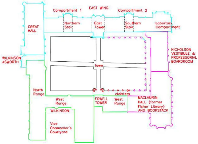
The Great Hall (Figure 4.1), located at the northern end of the Main Quadrangle of The University of Sydney (Figure 4.2), is a sandstone masonry structure designed in 1854 and completed in 1859 by Edmund Blacket, a British Colonial architect (Lawton and Steele 1981).
!
!
Figure 4.2. Main Quadrangle complex (HBO+EMTB Heritage Pty Ltd 2009) The building is composed of the following macro-elements:
• A symmetric front and back façades (Figures 4.3 and 4.4), dominated by a large window with mullions. The back façade is restrained by a horizontal roof.
Figures 4.3, 4.4. Front and back façades
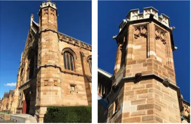
Figures 4.5, 4.6. Corner octagonal stair turret
• The church-like right side wall, characterised by six traceried windows divided by buttresses (Figure 4.7) and terminated with a projecting bay (Figures 4.8 and 4.9).
Figures 4.7, 4.8, 4.9. Buttresses and projecting bay on the right side wall
• The left side wall (Figures 4.10 and 4.11), restrained by the walls of the adjacent perpendicular building and buttresses (as the right side wall).
• The timber battens and the welsh slate roof is sustained by six ironbark timber trusses covered by ornamented cedar wood (Figures 4.12 and 4.13).
Figures 4.12, 4.13. timber trusses
A geometric survey has been conducted in order to determine the building dimensions. In the Appendix, the following tables are available:
• Plan of the Great Hall;
• Plan views of the front/back façades and left/right side walls; • Plan showing the thicknesses of the masonry elements;
• Representation of the timber trusses with indication of the elements’ thickness.
4.1.2. Material Survey
This section contains the specifications regarding the materials composing the analysed building (Tables 4.1, 4.2, 4.3, 4.4, 4.5).
Table 4.1. Masonry properties
Type: Sydney Basin Hawkesbury Sandstone (known as Sydney Sandstone or Yellow-block), a sedimentary rock named after the Hawkesbury River (Bertuzzi 2014).
f’m = kh · f’mb = 8.2 MPa
Characteristic compression strength of masonry calculated in accordance with Clause 3.3.2 AS 3700-2011, assuming:
-
kh = 1.3 assumed joint thickness factor-
f’mb = km √f’uc = 6.3 MPa• km = 1.4 assumed compressive strength factor
• f’uc = 20 MPa assumed characteristic unconfined
compressive strength
f’mt = 1 MPa Characteristic flexural tensile strength of masonry,
assumed in accordance with Clause 3.3.3 AS 3700-2011 f’ms = 0.3 MPa Characteristic shear strength of the masonry, assumed in
accordance with Clause 3.3.4 AS 3700-2011
E = 8000 MPa Elastic modulus (Bertuzzi 2014)
G = 3200 MPa Shear modulus (Bertuzzi 2014)
ν = 0.25 Poisson ratio (Bertuzzi 2014)
γm = 2446.48 kg/m3 = 24 kN/m3 Unit weight (Bertuzzi 2014)
Table 4.2. Timber trusses properties
Type: Broad-leaved red ironbark has been used for the structural members of the trusses. The cedar wood has been used as a decorative casing about the hardwood (Gamble 1999).
SD1 Strength group (seasoned), assumed in accordance with
AS/NZS 2878:2000
Bending Strength = 150 MPa Assumed in accordance with AS/NZS 2878:2000
E = 21500 MPa Elastic modulus, assumed in accordance with AS/NZS 2878:2000
G = 3200 MPa Shear modulus, assumed in accordance with AS/NZS 2878:2000
γ = 1100 kg/m3 = 10.79 kN/m3 Unit weight, assumed in accordance with AS/NZS
4.1.3. Construction History
The construction of the Great Hall began in 1854. The architecture style proposed by Blacket, whose project was inspired by the banqueting hall at Hampton Court Palace, the London Guildhall and the Westminster Hall of the Palace of Westminster in London, evokes the architecture of the late Gothic period, in order to link the new University of Sydney with the heritage of Cambridge and Oxford (Lawton and Steele 1981).
By May 1855, the foundations of the building were laid. After several revisions in the design, the Great Hall opened officially in 1859. Below are reported some photograph of the Great Hall under construction (Figures 4.14 and 4.15) and the exterior and interior views of the Great Hall (Figures 4.16 and 4.17).
Figures 4.14, 4.15. View of the Great Hall under construction (1856-1859) and portrait of Edmund Blacket and his daughter outside the Great Hall under construction (1857)
(Photographer: Professor John Smith; Publisher: University of Sydney Archives) Table 4.3. Timber battens properties
Type: Oregon wood F8 75x25 mm (HBO+EMTB Heritage Pty Ltd 2009) γ = 550 kg/m3 = 5.40 kN/m3 Unit weight
Gbattens = 0.27 kN/m2 Load per square metre
Table 4.4. Vapour underlay properties
Gvu = 0.24 kg/m2 = 0.00235 kN/m2 Load per square metre
Table 4.5. Slate roofing properties
Type: Welsh Slate from Penrhyn Quarry (Welsh Slate 2013).
t = 6 mm Thickness
Figures 4.16, 4.17. Exterior (1870) and interior (1896) views of the Great Hall (Publisher: University of Sydney Archives)
The Great Hall has required several repairs over the years. The most significant stages of the construction history are reported below.
1874 The Senate asked the architect to account for the condition of the roof. Although not at Blacket’s recommendation, it was decided to remove the two metre high stone angel that stood on a pinnacle above the front gable (HBO+EMTB Heritage Pty Ltd 2009).
1918 The Government Architect proposed to cover the deteriorated stones with timber paneling. However, the panels were never applied: instead, the stonework was treated and the pinnacles have been repaired (HBO+EMTB Heritage Pty Ltd 2009). 1951 The embers remaining after a plumber’s blowtorch were fanned into flame by an
evening breeze. Fortunately, the roof was saved: only the board roof-linings and some rafters were damaged (Gamble 1999). Over $7,000 were spent in order to repair the damage caused by the fire (HBO+EMTB Heritage Pty Ltd 2009).
1977 It was considered to remove the entire top section of the stonework at both gable ends due to the advanced deterioration of the sandstone. However, the work was not executed due to the prohibitive cost ($35,000) (HBO+EMTB Heritage Pty Ltd 2009).
1995 A Conservation Plan for the Main Quadrangle has been prepared by Orwell and Peter Phillips Architects and Wendy Thorpe, with a supplementary Conservation Plan Advice prepared by Barry MacGregor Architects Pty Ltd. Conservation works have been carried out (HBO+EMTB Heritage Pty Ltd 2009).
2001 Investigations about the stones (particularly in the right side wall), the timber trusses (checking for rot and termite damages) and the drainage and rising damp were carried out. A program to arrest the further deterioration and repointing the stones was carried out (HBO+EMTB Heritage Pty Ltd 2009).
4.1.4. Cracking State
The conservation project of 2011-2012 has successfully repaired and replaced the stonework, as no damage traces or cracking patterns are currently visible.
The most important problem for the structural safety and stability of the Great Hall, highlighted by the structural inspection of 2009, is the outward displacement of the front and back gables. The following image (Figure 4.18) represents the movement of the front gable.
2008 A further survey was conducted in order to identify and record the stones that need to be repaired or replaced within the university’s heritage maintenance program (Traditional Stonemasonry Company 2008).
2009 Structural inspections of the façades and the inside of the Great Hall were undertaken in order to assess the condition of the stone units and their integrity (Shreeji Consultant 2009). The following problems came to light:
• Some stone units have advanced weathering and salt activity. These units were cracking, exfoliating and loosing parts of the stones.
• The pinnacles were slender and unstable under seismic loads.
• The gables were falling out continuously and required stabilisation. The front gable has leaned out by 200 mm and cracks have opened up at the junction with the lateral walls.
An additional Conservation Management Plan for the Main Quadrangle has been produced by HBO+EMTB Heritage Pty Ltd in order to integrate the findings of the previous Conservation Plan with the updated information obtained from on site surveys and records of the work done since 1995. The scope of the Conservation Management Plan is to provide a guide to the future maintenance and conservation of the Main Quadrangle, in order to ensure that its significance is preserved.
2011- 2012
The last conservation project of the Great Hall was realised. This comprises: • The replacement of the damaged stones.
• The stabilisation of the gables.
• The replacement of the damaged and unstable pinnacles.
• The installation of a roofing system that satisfies the plumbing and drainage requirements.
!
As this displacement has occurred in static condition, it may be aggravated in dynamic condition, activating a hazardous overturning of the façade. For this reason, although the conservation project of 2011-2012 has accounted for this problem, periodic structural checks should be implemented in order to monitor and verify the reliability of the applied intervention.
4.1.5. Recent Interventions
The structural engineers that carried out the inspection in 2009 suggested the following interventions (Shreeji Consultant 2009):
• Urgently repair and replace the damaged stones in order to arrest the further deterioration and avoid the danger of stone pieces falling to ground and hurt the public.
• Arrest the gables movement by tying the front and back gables through ties in the roof structure.
• After the stabilisation and strengthen of the gables, reinstate the two metre high stone angel on top of the front gable.
• Stabilise the pinnacles for seismic loads, in order to avoid their collapse and the consequent possible damage to people or roof structure.
The last conservation project of 2011-2012 implemented the following interventions:
• Replacement of the damaged stones with fine to medium grained McCaffrey Pyrmont Yellowblock Sandstone, which closely matches the original sandstone of the Great Hall (Figures 4.19 and 4.20).
• Stabilisation of the gables. Steel plates 200x16 mm welded at the end and M20 bolts were used to connect the front and back gables to the roof structure at the purlins (Figures 4.21 and 4.22). Moreover, connection plates 200x16 mm and M20 bolts where installed at the intersection between the outer trusses and the upper purlins. Contrary to what has been suggested, the connection between the two gables through ties in the roof structure was not carried out.
Figures 4.21, 4.22. Steel plates 200x12 mm welded at the end and M20 bolts, used to connect the front and back gables to the roof structure at the purlins
• Replacement of the damaged and unstable pinnacles (Figures 4.23 and 4.24).
Figures 4.23, 4.24. Replacement of the damaged and unstable pinnacles
• Removal of the existing damaged state-work and battens (Figure 4.25) and installation of a new roofing system (Figures 4.26 and 4.27) that satisfies the plumbing and drainage requirements. The new system comprises:
-
Battens in two layers (75x25 mm F8 Oregon wood).-
Vapour permeable underlayFigures 4.25. Removal of the damaged battens
Figures 4.26, 4.27. Installation of a new roofing system
4.1.6. Historical and Artistic Goods
The Great Hall is recognised as having heritage significance and is listed on the State Heritage Register of the NSW Heritage Office. Therefore, all the retrofitting interventions shall be carried out considering the principles reported in paragraph 2.5.
Policy 69 of the Conservation Management Plan states:
“The Great Hall should be conserved in as near to its original form as possible and particular care should be taken to rejoin original details of floor tiles, stonework, joinery, painted finishes, fittings, stained glass, paintings, antiquities and busts. Missing or damaged original or early features in the Hall, including material, finishes and decorative schemes, should be restored and reconstructed.” (HBO+EMTB Heritage Pty Ltd 2009)
The following image (Figure 4.28) represents the historical-artistic goods included into the Great Hall.
!
4.2. Vulnerability Diagnosis
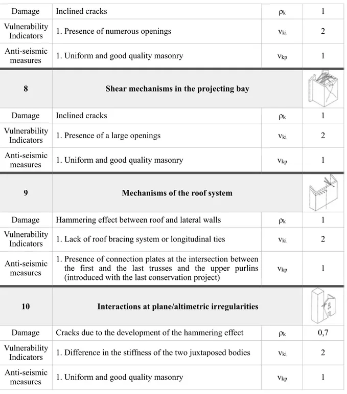
4.2.1. Vulnerability Survey and Computation of the Vulnerability Index
All the structural peculiarities playing a fundamental role in the seismic response of the Great Hall have been reported in the following table (Table 4.6) with the corresponding weight (ρk),
vulnerability and anti-seismic indicators (vki and vkp respectively). The purpose is computing
the vulnerability index (iv) (Table 4.7), which represents, on a statistical basis, the propensity
of the structure to be damaged by an earthquake. According to Clause 5.4.3 of the Italian Standard for the evaluation and reduction of the seismic risk of the cultural heritage (Direttiva PCM 2011), the vulnerability index is defined as the weighted average of the behaviour of the different structural elements:
!
where:
• ρk is the weight attributed to the k-mechanism (0.5 ≤ ρk ≤ 1), determined according to
Attachment C of the Italian Standard for the evaluation and reduction of the seismic risk of the cultural heritage (Direttiva PCM 2011);
• vki is the indicator of the degree of seriousness of the vulnerability (1 ≤ vki ≤ 3), determined
according to Table 5.1 of the Italian Standard for the evaluation and reduction of the seismic risk of the cultural heritage (Direttiva PCM 2011)
• vkp is the indicator of the degree of effectiveness of the anti-seismic measures already
implemented (1 ≤ vkp ≤ 3), determined according to Table 5.1 of the Italian Standard for the
evaluation and reduction of the seismic risk of the cultural heritage (Direttiva PCM 2011). iv= 1 6 ρk
(
vki− vkp)
1 k∑
ρk 1 k∑
+ 1 2 0≤ iv≤ 1Table 4.6. Vulnerability survey
1 Façade overturning (front façade)
Damage Detachment of the façade from the lateral walls ρk 1
Vulnerability Indicators
1. Evident gable movement
2. Lack of longitudinal ties or effective contrasting
elements vki 3
Anti-seismic
measures 1. Effective toothing façade-lateral walls vkp 1
Damage Detachment of the façade from the lateral walls ρk 1
Vulnerability
Indicators 1. Evident gable movement 2. Lack of longitudinal ties vki 3
Anti-seismic
measures 1. Effective toothing façade-lateral walls 2. Presence of a contrasting element (horizontal roof) vkp 2
3 Mechanisms of the gable (front/back façades)
Damage Overturning of the gable ρk 1
Vulnerability Indicators
1. Evident gable movement 2. Presence of a large opening
3. Lack of roof bracing system vki 3
Anti-seismic
measures 1. Presence of punctual links with the roof system (introduced with the last conservation project) vkp 1
4 Mechanisms in the façade plane (front/back façades)
Damage Inclined cracks (shear) - Vertical or curved cracks (rotation) ρk 1
Vulnerability Indicators
1. Lack of transversal ties or effective lateral contrasting elements
2. Presence of a large opening vki 3
Anti-seismic
measures / vkp 0
5 Lateral wall overturning (right side)
Damage Rotation of the lateral wall ρk 1
Vulnerability
Indicators 1. Lack of transversal ties vki 2
Anti-seismic
measures 1. Presence of buttresses (the capacity of which has been computed in Paragraph 4.2.2) vkp 1
6 Lateral wall overturning (left side)
Damage Rotation of the lateral wall ρk 1
Vulnerability
Indicators 1. Lack of transversal ties vki 2
Anti-seismic measures
1. Presence of buttresses (the capacity of which has been computed in Paragraph 4.2.2)
2. Presence of a contrasting element (adjacent building) vkp 2


![Table 4.9. Areas and centroids Area [m 2 ] x [m] A 0,265 0,260 B 1,310 0,195 C 0,904 0,263 D 1,562 0,465 E 0,974 0,429 F 3,073 0,605](https://thumb-eu.123doks.com/thumbv2/123dokorg/7414939.98562/51.892.207.463.90.628/table-areas-centroids-area-b-c-d-e.webp)
