PoS(SPIN2018)112
transversely polarized targets
Marco Statera∗, INFN Sezione di Milano, LASA laboratory, 20090 Segrate, MI, Italy E-mail:[email protected]
I. Balossino, Università di Ferrara and INFN, 44122 Ferrara, Italy
E-mail:[email protected]
L. Barion, Università di Ferrara and INFN, 44122 Ferrara, Italy
E-mail:[email protected]
G. Ciullo, Università di Ferrara and INFN, 44122 Ferrara, Italy
E-mail:[email protected]
M. Contalbrigo, INFN Sezione di Ferrara, 44122 Ferrara, Italy
E-mail:[email protected]
L. Del Bianco, Università di Ferrara and INFN, 44122 Ferrara, Italy
E-mail:[email protected]
P. Lenisa, Università di Ferrara and INFN, 44122 Ferrara, Italy
E-mail:[email protected]
M. M. Lowry, Jefferson Laboratory, 12000 Jefferson Avenue, Newport News, VA 23606, USA E-mail:
A. M. Sandorfi, Jefferson Laboratory, 12000 Jefferson Avenue, Newport News, VA 23606, USA
E-mail:[email protected]
F. Spizzo, Università di Ferrara and INFN, 44122 Ferrara, Italy
E-mail:[email protected]
G. Tagliente, INFN Sezione di Bari, 70126 Bari, Italy
PoS(SPIN2018)112
field from a detector. A hollow bulk superconductor can trap a transverse field that is present whencooled through its transition temperature, and also shield its interior from any subsequent field changes. A feasibility study with a prototype bulk MgB2superconducting cylinder is described. Promising measurements taken of the interior field retention and exterior field exclusion, together with the corresponding long-term stability performance, are reported. In the context of an electron scattering experiment, such a solution minimizes beam deflection and the energy loss of reaction products, while also eliminating the heat load to the target cryostat from current leads that would be used with conventional electromagnets.
23rd International Spin Physics Symposium SPIN2018 -10-14 September, 2018
Ferrara, Italy
PoS(SPIN2018)112
1. IntroductionThe determination of the spin-dependent amplitudes in a reaction between non-zero spin parti-cles always requires measurements with different orientations of the target polarization. In the case of spectrometers that are not accompanied by large magnetic fields at the target, such as those incor-porating torodial magnets, elaborate changes to a cryostat are usually required to provide holding fields for different target spin orientations. For spectrometers with strong magnetic fields in the target region, changing the natural target spin alignment becomes a formidable problem. The latter arises in the study of transverse spin effects with an 11 GeV electron beam in Hall-B of Jefferson Laboratory, where a transversely polarized hydrogen target must be placed within the longitudinal field of the central solenoid of the CLAS12 detector system [2,3,4]. We describe here a novel solution to such problems.
A hollow bulk superconductor is able to provide a transverse holding field inside, while ad-justing its internal currents to shield any outside field [5, 6]. The latter feature is an important improvement with respect to a conventional coil-based magnetic solution. Additional advantages include minimal space needed to fit within the target cryostat, maximal field compactness to reduce electron beam deflection in the transverse field, the absence of cryogenic load from current leads and the ability to operate without a copper stabilizer, which reduces the energy–loss of particles traversing the material. The particular choice of MgB2for the superconducting material results in a
small mass and Z in the path of reaction products, which further minimizes their energy–loss. Polar-ized hydrogen targets inherently require low temperatures, and as a result, the cooling of an MgB2
cylinder to 4K can be readily incorporated within the target cryostat. Finally, for the planned set of transverse experiments with polarized HD in the CLAS12 detector, the necessary Þeld manipula-tion is straightforward to accommodate within the installamanipula-tion procedure of the HDice frozen-spin polarized target [7,8].
The choice of magnesium diboride as the superconductor is motivated by its high critical current, critical field and transition temperature (39 K), by its availability in suitable shapes, as well as by its low density and low average-Z [9,10]. Over the relevant temperature and field regime, it operates as a hard type–II superconductor, despite the presence of two coherence lengths.
The details of an apparatus to test the transverse magnetic behavior [8, 11] of MgB2
cylin-ders are given in Section2. The measurements are presented in Section3, while conclusions are summarized in Section4.
2. A test bed for an MgB2prototype cylinder
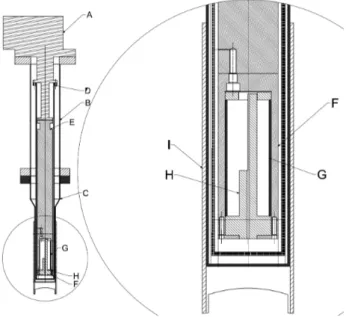
The design of the system has been described earlier [8], but additional details of the as-constructed setup are given here. Figs.1and2provides an overview.
2.1 Mechanical refrigerator
The superconducting cylinder is cooled by a cold head (Edwards 6/30). The lowest tempera-ture that has been reached is 11.1 ± 0.1 K. The sample temperatempera-ture is controlled by resistive heating of the cold head. The cold head, a thermocouple and a heater are all in a low field zone [8].
PoS(SPIN2018)112
2.2 External magnet
The magnetic field was provided by a VARIAN electromagnet (model V3603) with a max-imum current of 180 A. The magnet power supply (Agilent 6692A) was remotely controlled via GPIB. The maximum field generated at the center was about 980 mT, as measured by a Hall sensor (Arepoc HHP-NU). The Hall probe had an active area of 1.25 mm x 0.5 mm and was designed to operate with fields up to 5 T in the temperature range from 1.5 K to 350 K, with an additional correction [12] required at lower temperatures.
2.3 Vacuum system and thermal insulation
The vacuum system consist of two cylindrical chambers, a stainless steel top one, with all the vacuum penetrations, and an aluminum bottom one. The cold head is mounted on a CF100DN flange on the top of the upper chamber. A CF63DN flange holds a turbo pump (Agilent Turbo-V 81-M) backed by a scroll pump (Turbo-Varian SH110). Pressures are monitored by a Penning gauge (Pfeiffer PKR 251) placed at the front of the turbo and a Pirani gauge (Pfeiffer PRT81) at the exit. A CF40DN flange holds two sub-miniature D9 feedthroughs carrying three sets of 4–wire leads for the Hall probe and two sample temperature sensors, as well as two sets of 2-wire leads for the cold head thermocouple and the heater, to control the cold head temperature.
The MgB2 cylinder was fitted into the bore of a 380 mm long, 50 mm diameter sample can
- a copper rod, thermally connected to the second stage of the cold head (with 10 K nominal temperature). Surrounding this was a 3 mm thick copper thermal shield connected to the cold head’s first stage (77 K nominal temperature). Thin indium foils were used in all thermal joints. The aluminum chamber had an outer diameter of 70 mm and a wall thickness of 3 mm. Three layers of Myoflex sheet insulation (C7-110) [13] were wound around the 62 mm diameter thermal shield along the whole length of the aluminum vacuum chamber. Two bands of Myoflex foil, about 2 cm wide, were used as spacers at the bottom and the top of the sample can.
During the initial set of measurements (Figs. 3,4, and5), shaped epoxy spacers were used at the bottom of the thermal shield to define its position. In a subsequent improvement, the epoxy spacers were replaced with small (∼1 cm2) five-layer assemblies of myoflex, positioned at 120◦ intervals around the cylinder. This improved the insulation between the cooling arm and its shield and lowered the base temperature (Figs.6,7and8).
The pressure during test periods was below 10−8 mbar within the sample can and thermal shield. Nonetheless, the minimum temperature of the sample increased slowly over time. Since the base temperature could be recovered by warming up the system and pumping on the insulating vacuum, we attributed the slow temperature rise (eg. top panel of Fig. 5) to a buildup of frozen gas, which deteriorated the thermal isolation.
2.4 Temperature measurement
Two temperature sensors are placed on the bottom of the sample can, a Rhodium Iron (RhFe) calibrated sensor from Oxford Instruments, and a cryogenic linear temperature sensor (CLTS) from VISHAY. The CLTS is preferred above 30 K and the RhFe below. Accuracy of the measured temperature without magnetic field is about 10 mK, but increases to 50 mK with fields up to 1 T. Both sensors have high reproducibility: 5 mK at 4.2 K for the RhFe.
PoS(SPIN2018)112
Figure 1: An overview of the equipment [8] shows the iron yoke (1), the coils (2) and the iron poles (3). The aluminum chamber is inserted into a nylon support (4), which is fixed to the poles (3). The stainless steel (5A) and aluminum (5B) vacuum chambers are fixed to the coils (2) and the yoke (1). A cold head (6) is placed on top of the vacuum chamber (5); the turbomolecular pump (7) is connected to one side. Two additional flanges carry a pressure sensor (8), and electrical feedthroughs (9).
2.5 Data acquisition
LabView routines are used to 1) adjust the Oxford ITC-503S heater controller, 2) control and record the power supply settings of the external magnet, 3) readout and record pressure values from the Pfeiffer TPG256A, 4) acquire, interpret and store temperature sensor resistances measured by a Keithley scanner (199 System DMM/Scanner), and 5) readout and store data from the Hall probe controller (USB2AD by Arepco). The routines are synchronized to within ±0.5 seconds.
2.6 Thermal cycle
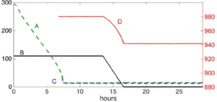
About 7.5 hours are required to cool from room temperature to near 13 K (see Fig. 3). Using the cold head heater at full power (65 W), it takes about one hour to heat the sample can to 60 K, which is done after each test to insure a complete transition before the next cool down and test. The trapped field disappears at a (CLTS) temperature of 38.8 K, close to the MgB2critical temperature
of 39 K. One and a half hours are needed to cool back to near 13 K.
3. Experimental Results
Measurements of the trapping and shielding of the transverse field from the external dipole were performed on a prototype MgB2 cylinder made by the Reactive Liquid Infiltration (RLI)
process [14], 86 mm long with a 39 mm outer diameter. While the nominal wall thickness was 2 mm, the material thinned to 1 mm in sections near the ends. This limited the maximum internal current, so that the thinned regions effectively dominated the performance at high field.
PoS(SPIN2018)112
Figure 2: A schematic drawing of the cold head and the inner parts of the chamber and the cylinder holder is shown with an expanded view on the right: the cold head (A), the stainless steel vacuum chamber (B), the aluminum vacuum chamber (C), the copper thermal shield connected to first stage of the cold head (D), the Copper rod connected to second stage of the cold head (E), the Copper chamber, which hosts the sample cylinder (F), the MgB2cylinder (G), a PFTE (C2F4, Teflon) Hall probe holder (H), and a PEEK (Polyether ether ketone) support (I).
A simulation tool is under development at JLAB [15], which calculates eddy currents in a material whose conductivity is continuously adjusted to reproduce the Bean–model critical state with the measured MgB2critical current density [10], as a function of field and temperature. Some
initial results are discussed in ref. [15] and a detailed comparison will be given elsewhere. Here we focus on the experimental performance.
3.1 Trapped field measurements i) Cooling and trapping:
The trapped field test is performed by field cooling (FC). With an external field applied, the sam-ple is cooled from room temperature to about 13 K. After the system stabilizes at the minimum temperature, the external field is ramped to zero while the residual field of the MgB2cylinder is
measured. A typical cycle is shown in figure3.
Note that there is no impact on the central field when the cylinder goes superconducting near 39 K, as expected of a hard Type–II superconductor. Furthermore, the granularity of the flux tube lattice penetrating the MgB2(∼150 nm) is not visible at this distance scale. The external field at a
current of 110 A, 980 mT, produces a trapped field of 942 ± 1 mT. The failure of the superconductor to fully replace the external field reflects the open ends of the cylinder, which prevent the induced super-currents from following an optimum path. As the ramp down proceeds, the critical current limitation forces the additional current to follow successively less–optimal paths, producing a faster than linear fall off.
PoS(SPIN2018)112
Figure 3: A field trapping cycle is shown, with the system starting at room temperature. The green–dashed (A) and blue–dashed (C) curves are the sample temperatures, in Kelvin with their scale on the left, as recorded with the CLTS and RhFe sensors, respectively. The external magnet current (B), in Amps with the left-hand scale, is shown in solid black. The field at the center of the MgB2cylinder (D), in mT with scale on the right, is shown as the solid–red curve.
Figure 4: Typical trapped field results are plotted for an 170 hour test period. The external magnet current, in Amps with the left-hand scale, is shown as the blue curve. The solid-black curves give the temperature, in Kelvin with the left-hand scale. The field in the center of the cylinder is shown as the solid red curves, in mT with their scale on the right. The temperature and central field are shown with an expanded scale on the top.
ii) Long term stability:
Long term trapped field measurements have been performed for different externally applied fields. A stability test performed at a current of 70 A (producing 664 mT) is shown in Fig.4. The trapped field is 644 mT, and both temperature and field show an extremely stable behavior out to 170 hours. (The oscillations of the magnetic field are artifacts from the readout, while the shorts spikes in the temperature are produced by the cold-head cycle.)
Extended stability measurements at a higher field are reported in Fig.5, where the trapped field and temperature have been tracked for about one month. During the FC, the current of the power supply is 110 A (producing 980 mT). After ramping down the external magnet, the internal MgB2
PoS(SPIN2018)112
field is 943 mT. We believe that the measured field decay of about 1.5 mT is due to the temperature increase of about 1 K over this extended period. In the lower panel of Fig.5, the first 135 hours are expanded in order to compare the behavior with the lower field measurements of Fig.4. Once again, the temperature and field are very stable. The simulated values of trapped fields at 70 A and 110 A are 637 mT and 938 mT, respectively, in good agreement with these measurements [15].
Following improvements in the thermal isolation of the sample region (Section 2.3), another FC study has been performed a year later (and after tens of thermal cycles), using the same external field. This has yielded similarly consistent values, as shown in Fig. 6. (Here, the trapped field appears slightly lower than that of Fig. 5(b), despite the lower temperature; this reflects small variations in positioning the Hall probe.) A reliably consistent level of performance in trapping fields following FC is evident.
Figure 5: (a) Trapped field measurements are logged here, out to 800 hours. The MgB2temperature and central field are shown as black and red curves, with scales on the left and right, respectively. The external field is zeroed at 15 hours. (Gaps in the top panel result from data recording failure.) The field drift of about 1.5 mT is due to the temperature drift. (b) The bottom panel shows the first 140 hours with an expanded scale.
Figure 6: The MgB2temperature and central field are shown here, with the same representation as in figure
5. These data were collected a year and tens of thermal cycles after those of figure5following improvements in thermal isolation, which led to the lower base temperature.
PoS(SPIN2018)112
3.2 Shielding field measurements
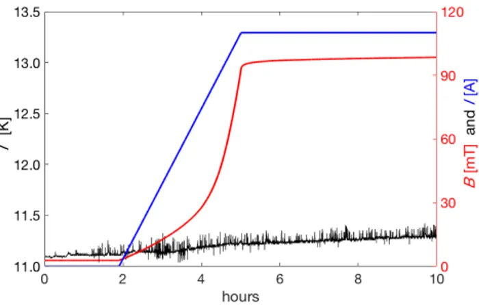
Transverse shielding measurements have been performed by powering the external magnet after zero field cooling (ZFC). A typical cycle for this measurement is shown in Fig. 7. The cylinder shields most of the field generated by the external magnet (980 mT), with only a small residual magnetic field penetrating the volume inside the cylinder.
The maximum critical current that can be sustained in MgB2is a strong function of temperature
[10], and as a result its effectiveness in shielding an external field is temperature dependent. This is confirmed in Fig.8, where the leakage field clearly tracks the temperature measured by the RhFe sensor. The residual field at the center of the cylinder is 120 ± 5 mT when the MgB2temperature
is in the range of 13.0 ± 0.5 K. (The simulated level of the leakage field is 71 mT at 13 K, in qualitatively good agreement with these observed results [15].)
While these studies were limited to 11 K, the trend in Fig.8projects very small residual fields within an MgB2shell operated at 4 K.
3.3 Moving the MgB2cylinder
The planned scheme for using an MgB2 shell requires that it be cooled in a transverse field
to trap transverse flux, after which a solid polarized target of HDice would be inserted vertically into the target cryostat. Next, the target cryostat would be rotated horizontal and wheeled into the bore of the CLAS12 solenoid. At that point the field of that solenoid would be ramped up for data taking. This process would subject the cylinder to unavoidable shocks and vibrations. Its ability to withstand this must be tested.
For a trial move, the vacuum chamber containing the MgB2 cylinder was extracted from the
external magnet by a crane. (The system remained connected to the vacuum pumps, and the cold head remained powered during the test.) A trapped field of 564.7 mT was maintained during removal and return with no detectable field loss.
Figure 7: A typical shielding cycle is shown, with the magnet energized after the system is cold. The external magnet current (in blue) in Amps, and the field at the center of the cylinder (in red) in mT, are plotted with their scales on the right. The temperature (in black) is shown versus time with its scale on the left. The temperature (RhFe) is 11.1 K at the starting point.
PoS(SPIN2018)112
Figure 8: The temperature and magnetic field penetration during shielding measurements is plotted over a20–day period. The temperature is 11.2 K after 6 h from the starting point of figure7and it ends at 13.2 K. The field penetration is visible and it tracks the temperature (RhFe sensor).
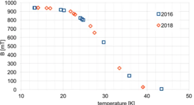
Figure 9: Preliminary results of the measurements of trapped field versus temperature performed in 2016 and 2018.
Figure 10: Preliminary results of the measurements of shielded field versus temperature performed in 2016 and 2018.
3.4 Repeatability
PoS(SPIN2018)112
repeatability of the measurements, given by the reproducibility of the temperature system, mechan-ics and the data acquisition system, and the reproducibility of the behaviour of the MgB2cylinder.
The preliminary results are shown in figures9and10, the datasets show very good reproducibility both in the low temperature and higher temperature measured performance. The 2018 measure-ment completes the 2016 in the trapped or shielded field region between 10 K and the critical temperature, the superconducting cylinder shows a good reproducibility also in this temperature range. These results are promising for the integration of these device in an experiment, where reproducibility of the field is and important feature.
4. Conclusion
A novel solution for the challenging magnetic problem of placing a transversely polarized target in a longitudinal field has undergone an initial feasibility study in an apparatus assembled for that purpose.
Several tests of trapping and shielding of a transverse field were performed on an MgB2
cylin-der at working temperatures between 11 and 13 K. The maximum trapped field at the center of the cylinder was 942 mT, limited by an available external field of 980 mT. During shielding studies, the same external field was reduced by an order of magnitude within the cylinder, with yet smaller values expected at temperatures near 4K. The trapped field was monitored for up to 800 hours, with only minor losses due to temperature drift, and the cylinder did not show any loss of trapped field due to vibration or movement of the assembly.
This feasibility study has demonstrated that a MgB2cylinder has the features essential for the
installation of a transversely polarized target into the CLAS12 detector at Jefferson Lab.
Potentially, this use of superconducting shells to manage local fields could have a variety of applications, such as providing the capability of easily switching spin orientations in a fixed-target cryostat, orienting spins in polarized gas targets internal to storage rings [16], or enabling the use of transverse fields in close proximity to the beam of a storage ring [17,18]. An advantage of the particular solution described here is the use of a relatively simple cryo-cooler to reach temperatures that are sufficient to support internal currents within the superconductor that can maintain or cancel up to 1 T fields.
Acknowledgements
We would like to thank Dr. G. Giunchi, materials consultant, Via Teodosio 8, Milano Italy, for useful discussions and for supplying the MgB2prototype cylinder used in this study.
This work was supported by the Istituto Nazionale di Fisica Nucleare, Italy, and by the US Department of Energy, Office of Nuclear Physics Division, contract DE-AC05-06OR23177 under which Jefferson Science Associates operate Jefferson Laboratory.
References
[1] pippo
[2] H. Avakian et al., (The CLAS Collaboration), JLab experiment C12-11-111 (2012), Transverse spin effects in SIDIS at 11 GeV with a transversely polarized target using the CLAS12 detector
PoS(SPIN2018)112
[3] H. Avakian et al., (The CLAS Collaboration), JLab experiment C12-12-009 (2012), Measurements oftransversity with dihardon production in SIDIS with a transversely polarized target
[4] H. Avakian et al., (The CLAS Collaboration) JLab experiment C12-12-010 (2012), Deeply Virtual Compton Scattering at 11 GeV with a transversely polarized target using the CLAS12 Detector [5] D. Frankel, Model for flux trapping and shielding by tubular superconducting samples in transverse
fields, IEEE Trans. Magn. 15 (1979) 1349.
[6] J. F. Fagnard et al., Magnetic shielding properties of a superconducting hollow cylinder containing slits: modeling and experiment, Supercond. Sci. Technol. 25 (2012) 104006.
[7] C. D. Bass et al., A portable cryostat for the cold transfer of polarized solid HD targets: HDice-I, Nucl. Instrum. Meth. Phys. Res. A 737 (2014) 107.
[8] M. Statera et al., A bulk superconducting magnetic system for the CLAS12 target at Jefferson Lab, IEEE Trans. Appl. Supercond. 115 (2015) art. n. 4501004.
[9] K. Vinod, R. G. Abhilash Kumar and U. Syamaprasad, Prospects for MgB2superconductors for magnet application, Supercond. Sci. Technol. 20 (2007) R1.
[10] J.J. Rabbers et al., Magnetic shielding capability of MgB2cylindersâ Supercond. Sci. Technol. 23 (2010) art. n. 125003.
[11] M. Statera et al, Magnetic System for the CLAS12 Proposalâ IEEE Trans. Appl. Supercond. 23 (2013) art. n. 3800304.
[12] Lubo Kopera, AREPOC s.r.o., private communication.
[13] Oxford Instruments Directâ Cryospares; www.cryospares.co.uk.
[14] G. Giunchi, High density MgB2 obtained by reactive liquid Mg infiltration, Int. Jour. of Mod. Phys. B17, (2003).
[15] M. M. Lowry et al., Magnesium diboride: A novel solution for a transversely polarized target holding field in CLAS12, in 22nd International Spin Symposium (Spin’16), Urbana, IL, Sep 25-30, 2016 [16] A. Dbeyssi et al., Superconducting Shielding for a Transversely Polarized Target at PANDA, in DPG
spring meeting (2017), Münster
[17] K. Capobianco-Hogan et al., A Magnetic Field Cloak For Charged Particle Beamssubmitted to Nucl. Instrum. Meth. Phys. Res. A; arXiv:1707.02361.
[18] G. Giunchi et al., Creep and relaxation phenomena in a long MgB2 tube subjected to transverse magnetic field, at 4.2 K, submitted to IEEE Trans. Appl. Supercond. 28 (2018) art. n. 6801705.
![Figure 1: An overview of the equipment [ 8 ] shows the iron yoke (1), the coils (2) and the iron poles (3)](https://thumb-eu.123doks.com/thumbv2/123dokorg/4704503.44973/5.892.334.560.139.450/figure-overview-equipment-shows-iron-yoke-coils-poles.webp)


