2017
Publication Year
2020-07-24T11:58:04Z
Acceptance in OA@INAF
An afocal telescope configuration for the ESA Ariel mission
Title
Da Deppo, V.; Middleton, K.; FOCARDI, MAURO; MORGANTE, GIANLUCA; Pace,
E.; et al.
Authors
10.1117/12.2296108
DOI
http://hdl.handle.net/20.500.12386/26629
Handle
PROCEEDINGS OF SPIE
Series
10562
Number
PROCEEDINGS OF SPIE
SPIEDigitalLibrary.org/conference-proceedings-of-spieAn afocal telescope configuration for
the ESA Ariel mission
V. Da Deppo
K. Middleton
M. Focardi
G. Morgante
E. Pace
R. Claudi
G. Micela
31. ente Biarritz, France on Space Optics 18-21 October www.icso2016.com
ICSO 2016
International Conference on Space Optics
Biarritz, France
18–21 October 2016
Edited by Bruno Cugny, Nikos Karafolas and Zoran Sodnik
An afocal telescope configuration for the ESA Ariel mission
V. Da Deppo
K. Middleton
M. Focardi
G. Morgante
et al.
International Conference on Space Optics 2016, edited by Bruno Cugny, Nikos Karafolas, Zoran Sodnik, Proc. of SPIE Vol. 10562, 105624W · © 2016 ESA and CNES
ICSO 2016 Biarritz, France International Conference on Space Optics 18 - 21 October 2016
AN AFOCAL TELESCOPE CONFIGURATION FOR THE ESA ARIEL MISSION
V. Da Deppo1,2, K. Middleton3, M. Focardi4, G. Morgante5, E. Pace6, R. Claudi2, G. Micela7
1CNR-IFN Padova, Via Trasea 7, 35131 Padova, Italy .2INAF-Osservatorio Astronomico di Padova, Vicolo
dell’Osservatorio 5, 35122 Padova, Italy. 3RAL Space-STFC Rutherford Appleton Laboratory, Harwell Campus, Didcot OX11 0QX, UK. 4INAF-Osservatorio Astrofisico di Arcetri, Largo E. Fermi 5, 50125 Firenze, Italy. 5INAF-IASF Bologna, Area della Ricerca, Via Piero Gobetti 101, 40129 Bologna, Italy. 6Dept. of Physics and Astronomy-Università degli Studi di Firenze, Largo E. Fermi 2, 50125 Firenze, Italy. 7INAF-Osservatorio
Astronomico di Palermo, Piazza del Parlamento 1, 90134 Palermo, Italy.
ABSTRACT
ARIEL (Atmospheric Remote-sensing Infrared Exoplanet Large-survey) is one of the three candidates for the next ESA medium-class science mission (M4) expected to be launched in 2026. This mission will be devoted to observing spectroscopically in the infrared (IR) a large population of known transiting planets in the neighborhood of the Solar System, opening a new discovery space in the field of extrasolar planets and enabling the understanding of the physics and chemistry of these far away worlds.
ARIEL is based on a 1-m class telescope ahead of two spectrometer channels covering the band 1.95 to 7.8 microns. In addition there are four photometric channels: two wide band, also used as fine guidance sensors, and two narrow band. During its 3.5 years of operations from L2 orbit, ARIEL will continuously observe exoplanets transiting their host star.
The ARIEL optical design is conceived as a fore-module common afocal telescope that will feed the spectrometer and photometric channels. The telescope optical design is composed of an off-axis portion of a two-mirror classic Cassegrain coupled to a tertiary off-axis paraboloidal mirror.
The telescope and optical bench operating temperatures, as well as those of some subsystems, will be monitored and fine tuned/stabilised mainly by means of a thermal control subsystem (TCU-Telescope Control Unit) working in closed-loop feedback and hosted by the main Payload electronics unit, the Instrument Control Unit (ICU). Another important function of the TCU will be to monitor the telescope and optical bench thermistors when the Payload decontamination heaters will be switched on (when operating the instrument in Decontamination Mode) during the Commissioning Phase and cyclically, if required. Then the thermistors data will be sent by the ICU to the On Board Computer by means of a proper formatted telemetry. The latter (OBC) will be in charge of switching on and off the decontamination heaters on the basis of the thermistors readout values.
I. INTRODUCTION
ARIEL (Atmospheric Remote-Sensing Infrared Exoplanet Large-survey) is one of the M4 proposed missions in the framework of the ESA Cosmic vision program [1]. It is a mission conceived to study the atmospheres of exoplanets orbiting close to nearby stars. The aim is to measure the atmospheric composition and structure of hundred(s) of exoplanet atmospheres, using spectroscopy in the infrared wavelength. This will allow to explore the nature of exoplanet atmospheres and interiors and study the key factors affecting the formation and evolution of planetary systems.
ARIEL will provide spectroscopic information on the atmospheres of a large selected sample of exoplanets (~500) allowing the compositions, temperature (profile), size and variability to be determined at a level never previously attempted [2].
ARIEL will measure the reflected/emitted/transmitted spectra of a sample of exoplanetary atmospheres over the visible to the thermal IR wavelength range. Planets under study will extend from gas giants, i.e. Jupiter-like planets, to Neptune-like and super-Earths [3].
For its ambitious scientific program, ARIEL is designed as a dedicated survey mission for transit and eclipse spectroscopy, capable of observing a large and well-defined planet sample within its 3.5-year mission lifetime. Using the knowledge of the planetary ephemerides, transit and eclipse spectroscopy methods allow to differentiate the signals coming from the planet and the host star. This enables to measure atmospheric signals from the planet at levels of at least 10-4 relative to the star and, given the bright nature of targets, also permits more sophisticated techniques, such as phase curve analysis and eclipse mapping, to give a deeper insight into the nature of the atmosphere. This requires a specifically designed, stable payload and satellite platform with broad, instantaneous wavelength coverage to detect many molecular species, probe the thermal structure, identify clouds and monitor the stellar activity as well.
Transit spectroscopy means that no angular resolution is required and detailed performance studies show that a telescope collecting area of 0.64 m2 is sufficient to achieve the necessary observations on all the ARIEL targets within the mission lifetime. ARIEL will carry a single, passively-cooled, highly capable and stable spectrometer
Optical bench with focal plane instruments and
radiator Telescope baffle Secondary mhor (M2) with refocusing mechanism V-Grooves Servic. Module (SVM)
Cold Payload Units (PLM)
M2& Reform
Mech
Telescope & Baffle
NU
Optical Bench & Metering Structure
FGS / NIRPhot (Inc. Detector & CFEEI
Common Optics MS&
nPRR
Meth.
IRSpectrometer (Inc.
Detector & CFEE)
3 o-, nlIhrJ Support Structure Cooler Compressor
ICSO 2016 Biarritz, France
International Conference on Space Optics 18 - 21 October 2016
covering 1.95–7.80 µm with a resolving power of about 200 mounted on a single optical bench with the telescope, and a Fine Guidance Sensor (FGS) that provides closed-loop feedback to the high stability pointing of the spacecraft and simultaneous information on the photometric stability of the target stars.
ARIEL is complementary to other international facilities (such as TESS [4], to be launched in 2018) and will build on the success of ESA exoplanet missions such as Cheops [5] and PLATO [6], which will provide an optimized target list prior to launch.
II. SPACECRAFT AND SCIENCE PAYLOAD
A. Spacecraft architecture
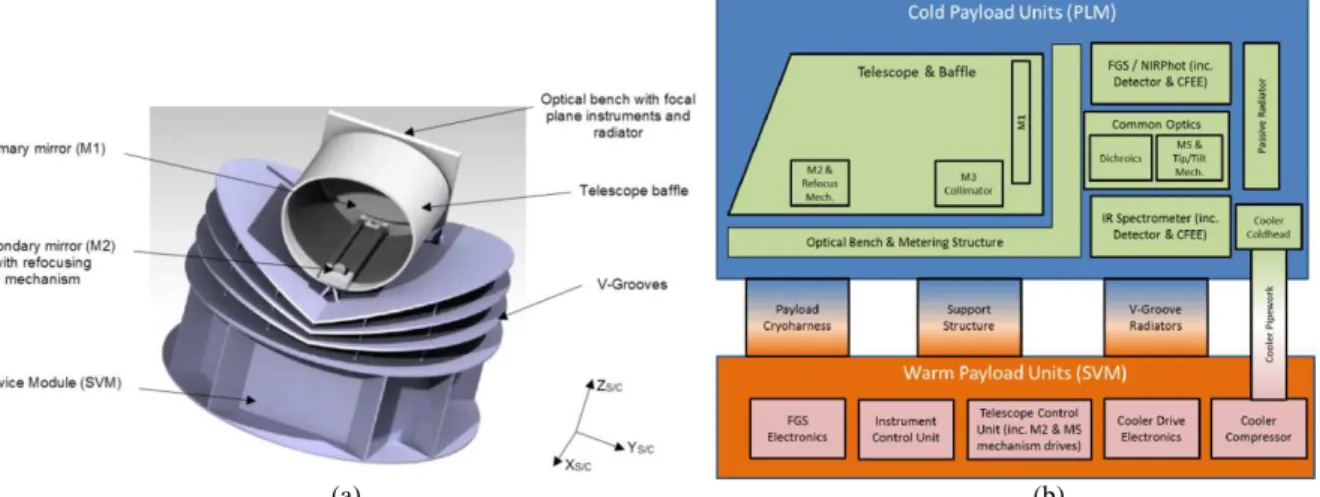
A horizontal configuration has been adopted as baseline (see Fig. 1a). The X axis of the ARIEL reference system corresponds with the telescope pointing axis, the Z one is the launch vehicle symmetry axis (vertical) and Y completes the right-handed triad. The instrument boxes are accommodated on the optical bench behind M1, enabling a direct view to deep space to provide direct radiative cooling for critical elements such as NIRPhot detectors (see par. IIE). The Sun is located below the platform. The V-Grooves and volumes are designed to accommodate a ±25° angle and a ±5° angle clearance respectively around the X-axis and Y-axis wrt the Sun vector.
To achieve the required photometric stability, a good pointing stability needs to be provided by the spacecraft during one observation. For this purpose, the FGS looking to the target star in parallel to the spectrometer will be accommodated on the payload and used by the AOCS, this module will also house the NIR photometer channels.
The spacecraft can be considered as composed of a cold Payload module (PLM), containing the telescope and the instruments with their thermo-mechanical hardware, and a warm Service module (SVM) that includes all mission supporting systems together with the PLM and cryogenic control units.
B. Payload module architecture
The ARIEL PLM consists of an integrated suite of telescope, spectrometer and FGS/photometer along with the necessary supporting hardware and services (such as optical bench, harnesses thermal control etc). The mission carries a single dedicated payload for its primary mission objectives; this payload will be developed and delivered by the ARIEL payload consortium [7]. A block diagram of the payload architecture is shown in Fig. 1b.
The ARIEL afocal telescope is an off-axis configuration and consists of 3 mirrors (M1, M2 and M3). There will be a baffle around M1 to control the out-of-field scattered straylight. The telescope is followed by a fixed plane mirror M4 and a tip/tilt M5 mirror with a fine steering mechanism, which closes the loop from the FGS and AOCS and minimizes the effect of the reaction wheel spikes. Then a number of plane dichroic mirrors split the light to redirect it toward the fine guidance and spectrometer modules.
Since calibration requirements are still TBC, additional hardware might be added within the instrument volume. An IR calibration source based on the heritage of the JWST MIRI calibration system [8] and injected in the center of the M5 mirror has been considered as the first possible solution.
The PLM will interface to the SVM via a set of thermally isolating support struts, or bi-pods, and will be radiatively shielded from the SVM and the solar input loads by a set of 3 V-Grooves (VGs). The isolating supports and VGs are proposed to fall under the responsibility of the spacecraft prime contractor, all hardware fully in the cold zone of the spacecraft will be provided by the consortium.
(a) (b)
Fig. 1. In (a) schematics of ARIEL spacecraft baseline configuration: main components and S/C reference
ICSO 2016 Biarritz, France International Conference on Space Optics 18 - 21 October 2016
This enables a completely aligned and verified payload to be delivered to spacecraft level, thereby minimizing the complexity (and risks) associated with the full spacecraft AIV program and allowing the best possible calibration of the payload without the complexity associated with a full S/C test. An active cooler is baselined for the detectors of the spectrometer that require an operating temperature ≤ 40 K.
The baseline design of the PLM includes two active mechanisms in the payload. The first is the refocusing mechanism on the telescope M2 mirror, which is used to ensure that the alignment and image quality of the telescope system are good after launch and cooldown. The second is the tip-tilt mechanism on M5 used as part of the AOCS system to close the loop from the FGS.
The ARIEL cold units are optically coupled via a common optics module and all referenced to the common optical bench. The units are thermally isolated by the S/C-provided VG shields and the detectors are cooled by a dedicated radiator and the active cooler cold end, integrated on the OB.
The baseline architecture splits the payload into two major sections, the cold payload module (PLM) and the items of the payload that are mounted within the spacecraft service module (SVM) [9].
C. Service module architecture
The ARIEL warm units are integrated in the SVM. These include the payload electronics, which consists of three boxes that act as Remote Terminal Units (RTUs) via Spacewire to the S/C Command and Data Management System (CDMS). All high level commands, operational sequencing and data storage are within the S/C CDMS.
D. PLM mechanical design
The main mechanical units composing the PLM are:
• the V-Grooves,
• the bipods and supporting struts,
• the Telescope Assembly (mirrors, struts and baffle),
• the Optical Bench,
• the Instrument Box (RTU modules, common optics, radiator).
The VGs are high efficiency, passive radiant coolers, providing the first stage of the PLM cooling system. The Planck mission has definitely demonstrated their efficiency as passive cooling systems [10]. Parasitic heat from warmer sections of the S/C is intercepted by the VGs and radiated to space after multiple reflections between the adjacent shields. To achieve this, VGs surfaces must have a very low emittance coating, i.e. a high reflection/mirroring material needed to reflect heat radiation. Only the upper surface of the last VG (VG3), exposed to the sky, is black coated with a high emissivity material to maximize the radiative coupling, and so heat rejection to deep space. The ARIEL VG system consists of a set of three specular shields, composed of six half circles arranged in a “V-shaped” configuration, angled along the diameter parallel to the S/C X axis (see Fig. 1). A constant angle of 7° has been assumed as the inclination between VGs, resulting in a set of 7°-14°-21° for the three shields, separated by a gap of 100 mm at the vertices. VGs are mechanically designed as a simple sandwich of Aluminum alloy (series 1000 or 6000) layers.
The PLM is supported by three bipods mounted onto the PLM/SVM interface plate. One bipod is at the front of the telescope baffle in central position. The other two are on the rear side of the Telescope Assembly, supporting the OB and the baffle on two points. The VGs are also mechanically and thermally attached to the three bipods plus the extra support provided by eight auxiliary struts (TBC). The need for these extra supports and their thermo-mechanical design will be investigated in the next phase of the analysis. Bipods preliminary thermo-mechanical configuration is based on the Planck design. They are assumed as hollow cylinders made of GFRP (R-Glass + Epoxy), a low conductive material with good structural properties. To increase their mechanical stiffness the inner volume of the cylinders is filled with low thermally conductive rigid foam. The eight extra supporting struts for the VGs are positioned in the outer boundary part of the PLM in order to support the radiators’ edges. They are designed as hollow GFRP cylinders extending from the SVM/PLM interface to the lower surface of the last VG.
E. FGS and its objectives
The Fine Guidance System (FGS) main task is to ensure the centering, focusing and guiding of the satellite, but it will also provide high precision astrometry and photometry of the target for complementary science. In particular, the data from the FGS will be used for de-trending and data analysis on ground. The sensor uses star light coming through the optical path of the telescope to determine the changes in the line of sight of the ARIEL instrument. The attitude measurement is then fused with the information from the star tracker, and used as input for the control loop stabilizing the spacecraft through the high performance gyros.
To meet the goals for guiding and photometry, four spectral bands are defined:
• FGS – Prime: 0.8–1.0 µm,
• FGS – Redundant: 1.8–1.9 µm,
ICSO 2016 Biarritz, France International Conference on Space Optics 18 - 21 October 2016
• NIR-Phot1: 0.50–0.55 µm,
• NIR-Phot2: 1.65–1.70 µm.
The information from all the channels is used as a stellar monitor and to provide photometric information to constrain the VIS/NIR portion of the exoplanet spectra. The information from FGS prime channel will be used as the nominal FGS information to feed into the AOCS. In case of failure in the system then the information from the other channels can be used instead. The spectral bands are selected from the incoming light using dichroic filters (see Fig. 2a).
The main requirement of the FGS is the centroiding performance of 10 milli-arcsec at 10 Hz. The FGS could also be used for focusing the main telescope and support this activity through a dedicated imaging mode. For the best support of the operating modes, several centroiding and data extraction algorithms will be implemented, fully configurable by parameter and command.
This system may also be used during the commissioning of the payload to iterate and optimize the telescope focus and spherical aberrations by an iterative loop (with ground control) feeding into the M2 mirror mechanism.
F. ARIEL IR Spectrometer (AIRS)
The prime science payload for ARIEL is a broadband, low resolution NIR spectrometer operating between 1.95 µm and 7.8 µm. The IR spectrometer can be split into multiple channels but not at wavelength with key spectral features. This spectrometer is mounted on an Optical Bench hosting also the FGS and the interface to the telescope, amongst which the field of view is shared between different wavelength ranges.
The baseline design foresees two spectrometers with independent optical channels: the first one covering the shorter waveband (1.95–3.9 µ m), the second the longer waveband (3.9–7.8 µm). The design has evolved considerably since the start of the proposal, with the original grating solution being replaced with a prism [11]. The spectrometer detector (or detectors in case the spectrometer is subdivided in multiple channels) is expected to require active cooling, with a nominal operating temperature of ~35 K, to provide the goal performance with the chosen baseline detector.
III. TELESCOPE OPTICAL DESIGN
A. Telescope design requirements
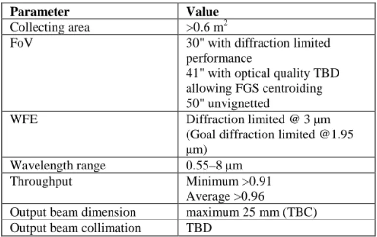
The telescope optical layout has been designed in order to provide the optical requirements reported in Tab. 1. The requirement on the collecting area of 0.6 m2 implies an entrance pupil of the order of 1 m in diameter. The collecting area is related with the minimum intensity (magnitude) of the observable target.
Tab. 1. Summary of the telescope optical requirements.
Parameter Value
Collecting area >0.6 m2
FoV 30" with diffraction limited performance
41" with optical quality TBD allowing FGS centroiding 50" unvignetted
WFE Diffraction limited @ 3 µm (Goal diffraction limited @1.95
µm)
Wavelength range 0.55–8 µm Throughput Minimum >0.91
Average >0.96
Output beam dimension maximum 25 mm (TBC) Output beam collimation TBD
The design performance is driven by the requirement that the as-built quality of the telescope system has to be diffraction limited at 3 µ m over a FoV of 30", i.e. equivalent to an RMS WFE of 220 nm.
To guarantee the required throughput without increasing the size of the primary mirror, that is the entrance pupil of the telescope, the optical design has to be unobscured. The unobstructed solution also assures the energy in the PSF is primarily contained inside the first Airy disk and not spread towards the secondary rings.
The wavelength coverage and the global FoV of the telescope are determined by the requirements on the instruments following the telescope, i.e. the FGS and the AIRS.
B. Telescope FoV determination
In the determination of the FoV for the telescope, there are three aspects to consider: the FoV required for the FGS, the FoV required for the IR spectrometer (AIRS) and the FoV required for the telescope itself.
D5 R<1Jym Tal.9um D3 R<LOym T>IAym DI Rc1.9Rm T>1.95ym To AIRS 1.95 tom to >7.8 pm
ICSO 2016 Biarritz, France
International Conference on Space Optics 18 - 21 October 2016
(a) (b)
Fig. 2. In (a) scheme of the FGS channels and dichroics system. In (b) Final telescope FoV; all dimensions are
to scale.
For each of these not only the nominal scientific FoV has to be taken into account but also the extended FoV needed for accounting for misalignment (alignment pointing error (APE)) or for channel calibration. For example, in the spatial direction of the IR spectrometer an extended FoV is needed for monitoring the background (i.e. zodiacal and thermal background but also detector dark current). FGS has to be able to acquire the source also in the coarse alignment mode, when the feedback with the M5 mirror is not active, which implies a larger FoV for the telescope.
Moreover an additional FoV requirement of 10" is intended to allow for off-movements of the telescope with respect to the instrument optical bench (for example due to launch loads, settling of the structure post-launch and dimensional changes on cool-down).
A 26.4" diffraction limited telescope FoV is required to ensure there is a well resolved PSF at the center of the slit. A larger 37" telescope FoV is required to allow the FGS to acquire a star and center it on the slit. The image quality level over this 37" annulus is TBD but it can be of lower quality, sufficient to allow the star centroid to be well enough resolved to be initially located and then brought to the center of the FGS FoV, where the telescope image quality is better. We refer to this annulus as the ‘FGS acquisition’ FoV. A still larger telescope FoV, extending to 46", is required to capture the slit background. There are no image quality requirements over this additional FoV; the only real requirement is for the FoV to be unvignetted so that background photons reach the slit. We refer to this annulus as the ‘background’ FoV.
However, this situation does not allow any margin for misalignment of the FGS and AIRS. They must be co-aligned to better than ±5" in any case, or else the PSF cannot be located on the center of the slit and in the FGS FoV at the same time. We also need to allow some margin for the fact that the telescope to OB alignment will be set to some datum on the optical bench, and there may be some residual misalignment between that datum and the individual FGS and AIRS instruments. It is reasonable to suppose that these misalignments will be small in comparison to the offset between telescope and OB, given that AIRS and FGS will be integrated on a single optical bench.
For the moment we assume that both the FGS and AIRS will be aligned to a datum on the instrument optical bench (for example an optical reference cube) to within ±2", implying a maximum co-alignment error between the two of 4". We then assume that this reference cube is the datum to which the telescope is aligned. This implies that we must add a 4" margin on all of the telescope FoVs to allow for these alignment errors. This gives the final telescope FoVs shown in Fig. 2b and summarized in Tab. 2.
Tab. 2.Summary of FoV requirements. Telescope FoV values are rounded to the nearest arcsec.
Designation FoV (arcsec)
AIRS 6.4 x 26.4
FGS 17
Telescope: Diffraction limited 30 Telescope: FGS acquisition 41 Telescope: Background 50
C. Telescope design characteristics
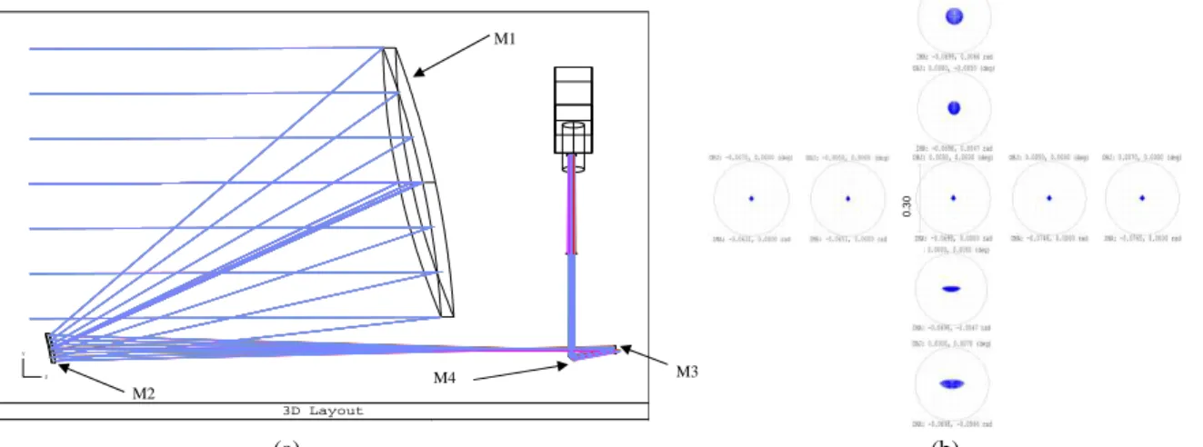
The baseline telescope design is an afocal unobscured off-axis Cassegrain telescope (M1 and M2) with a recollimating off-axis parabolic tertiary mirror (M3) (see Fig. 3a). All the mirrors share the same optical axis.
ICSO 2016 Biarritz, France International Conference on Space Optics 18 - 21 October 2016
3D Layout X
Y
Z
(a) (b)
Fig. 3. In (a) scale drawing of the telescope – view in Y-Z plane. In (b) Spot diagrams for the telescope in afocal
image space (units are mrad). The spot diagrams are compared with the Airy disk calculated at the nominal telescope diffraction limited wavelength of 3 µ m.
Note that the optical reference system (shown in Fig. 3a) is different from the S/C one. The telescope is accommodated horizontally with its optical axis (Z) along the S/C X axis.
The system aperture stop/entrance aperture is located at the M1 surface. M1 aperture is an ellipse with major axis dimensions of 1100 mm x 730 mm. The complete characteristics of the optical design are summarized in Tab. 3a.
In Tab. 3b the parameters (radius of curvature, conic constant, off-axis, etc) of the telescope mirrors are described.
Tab. 3. (a) Summary of the telescope optical design characteristics. (b) Mirrors parameters description.
(a) (b) Optical element M1 M2 M3 R (mm) -2314.3 -229.9 -493.9 k -1 -1.4 -1 Off-axis (mm) (y direction) 500 51 47 Clear Aperture Radius (mm) Elliptical, 550 (x) by 365 (y) Elliptical, 56 (x) by 40 (y) Elliptical, 15 (x) by 11 (y) Type Concave mirror Convex mirror Concave mirror
D. Telescope optical performance
The raytracing analysis and design optimization have been done by means of the raytracing software Zemax. To assess the quality of the telescope and determine the optical performance, since the telescope is afocal, the spot diagrams can be given using an ideal focusing paraxial lens with an on purpose focal length, or using the afocal image space option appropriate for systems with collimated output. The spot diagrams obtained with this second method are reported in Fig. 3b; note that units in this case are radiants. In the figure, the spot diagrams calculated over a FoV of 37", corresponding to the nominal ‘FGS acquisition FoV’, are compared with the Airy disk diameter calculated at a wavelength of 3 µ m, i.e. 0.37 mrad.
IV. TELESCOPE THERMAL CONTROL
The telescope is passively cooled to ≤70 K and thermal control is based on a passive/active approach. A preliminary telescope mechanical configuration and a high level scheme of the telescope assembly are shown respectively in Fig. 4a and Fig. 4b.
The telescope baffle provides a large radiator area with a good view to deep space; this gives sufficient radiative cooling to dump the parasitic loads from the PLM support struts, cryo-harnesses and radiative load from the final VG. Temperature control of the mirrors is achieved by partial thermal decoupling from PLM units: each mirror is mounted on its supporting structure by insulating struts with a total conductance of less than 0.01 W/K.
Parameter Values
Optical concept
Off-axis Cassegrain plus off-axis parabolic mirror
Afocal design Focal length 12.1 m
Pupil size Ellipse with major axis 1.1 m x 0.73 m Focal ratio 11 (or 16.5) Angular magnification -43 Scale @ telescope focus 58 µm/" 0 .3 0 M1 M2 M3 M4
Refocusing Meth Telescope
Ni
Beam M2 Baffle NOMINAL SECTION SP W. +28V TM/TC DSU GPIO I I AIRSSingle or redundant detector /CFEE
cPCI SPI or Power WFEE v-1 . DPU SCU
TC-_
(6U) (3U) (311) ! (3FPGA MUX MUX
ADC I ADC
Met, Dac ¡ Dac SPI or
SOW Powe
Secondary Power (MAIN)
REDUNDANT SECTION T TM/I C +28V DSUA cPCI WEEP FPGA GPIO I I
Secondary Power (RED) Back Panel
ARIEL ICU: 4 boards + 1 BP
TCS mmsnr. ICS neYr. PLA1 T1rtm11M PLAA TCS TCU U
ICSO 2016 Biarritz, France
International Conference on Space Optics 18 - 21 October 2016
(a) (b)
Fig. 4. (a) ARIEL telescope mechanical configuration. (b) Simple scheme of the Telescope Assembly thermal
configuration.
This configuration will help in filtering out all potential instabilities with periods of the order of 10–100 s originated in the PLM.
For the primary mirror, the high thermal capacitance, due to its mass, will allow a higher level of passive filtering, damping instabilities at lower frequencies (with periods of the order of few hours). The slower fluctuations (with periods of the order of several hours or longer) that could be transmitted to the optics will be smoothed by the active control system based on a PID type feed-back loop.
The telescope will also incorporate contamination control heaters on the M1 and M2 mirrors and on the PLM optical bench. These heaters will be active during the early orbit operations to ensure that the sensitive optical surfaces remain warmer than the support structure through the critical parts of cooldown. A temperature delta of ~40 K will be maintained between the baffle (which will act as a contamination getter for water and other contaminants being off-gassed by the PLM) and the optical surfaces. An initial calculation of the power required to maintain this temperature gradient shows that approximately 100 W of heater power is required during this phase. This would hold the sensitive surfaces at 200 K while the baffle cools below 160 K where the H2O will freeze out.
V. TELESCOPE CONTROL UNIT
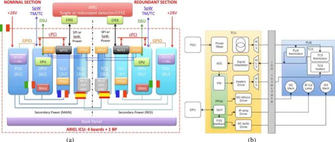
The telescope and optical bench operating temperatures, as well as those of some subsystems, will be monitored and fine tuned/stabilized mainly by means of the thermal control subsystem Telescope Control Unit (TCU) working in feedback closed-loop and hosted by the main Payload electronics unit, i.e. the Instrument Control Unit (ICU) [12].
The ICU baseline electrical architecture foresees four electronics boards, as illustrated in Fig. 5a.
(a) (b)
Fig. 5. In (a) ICU baseline electrical architecture showing the main present national responsibilities. In (b) TCU
baseline electrical architecture (courtesy IEEC-CSIC).
In order to accomplish the TCU requirements, the board hosts the PLM thermal monitoring logic, the thermal control logic and the drivers of: M2 refocusing mechanism, M5 tip/tilt mechanism and IR calibration lamp. It
ICSO 2016 Biarritz, France International Conference on Space Optics 18 - 21 October 2016
will also host a power stage to feed all subsystems, a communication link to ICU’s DPU and a feedback loop control from FGS for M5 driver logic (as shown in Fig. 5b).
For the thermal monitoring of the PLM, 50 thermistors will be powered by a stable current source and readout one by one with an ADC by means of a multiplexing stage. The redundant thermistors will be read by the redundant TCU board in order to avoid cross-strapping and reduce the overall complexity. The relevant thermal data will be sent to ICU’s DPU for housekeeping telemetry formatting towards the S/C, through the communication link.
The thermal control of the TCS (see Fig. 5b) subsystems (which are placed between critical detectors/mirrors and their thermal sink) will be carried out by monitoring their temperature, as explained previously, and activating their heaters once the correction has been calculated by the FPGA logic (a PID control loop). The heaters power will be supplied by its driver stage with a Pulse Width Modulator (PWM), if the power budget from ICUs permits it.
The M2 and M5 mechanisms and IR lamp are in an early stage of design. Each one will be controlled by the FPGA dedicated logic and powered by its driver stage, assuming that the power budget from ICU is enough. It is not foreseen any feedback loop for these subsystems except for M5. It requires data from FGS in order to operate, which will come through the ICU’s DPU, using a proper communication link (TBC).
VI. CONCLUSIONS
In this paper the main characteristics of the ARIEL telescope have been presented. An introduction on the mission design and goals has been given together with a description of the various elements composing the spacecraft and payload.
The afocal telescope layout solution has been described and the different requirements and characteristics have been discussed. In particular the requirements on the FoV of the telescope related to the spectrometer and field guidance channels have been illustrated in detail.
The theoretical performance of the baseline telescope layout, an off-axis Cassegrain plus a collimating off-axis paraboloidal mirror, has been shown.
A preliminary study on the passive/active thermal control of the instrument has been given. The telescope is passively cooled at an operating temperature less than 70 K.
The Instrument Control Unit (ICU) baseline electrical architecture together with that of the Telescope Control Unit (TCU) have been described. The optical bench operating temperatures, as well as those of some subsystems, will be monitored and fine tuned/stabilized mainly by means of the thermal control subsystem working in feedback closed-loop.
ACKNOWLEDGMENTS
This activity has been realized under the Agenzia Spaziale Italiana (ASI) contract to the Istituto Nazionale di Astrofisica (INAF) (ARIEL 2015-038-R.0).
REFERENCES
[1] L. Puig, G. L. Pilbratt, A. Heske, I. Escudero Sanz, and P.-E. Crouze, “ARIEL: an ESA M4 mission candidate”, Proc. SPIE, vol. 9904, 99041W, 2016.
[2] G. Tinetti, et al., “The science of ARIEL (Atmospheric Remote-sensing Infrared Exoplanet Large-survey)”, Proc. SPIE 9904, vol. 9904, 99041X, 2016.
[3] ARIEL SST, “ARIEL Science Requirements Document”, ESA-ARIEL-EST-SCI-RS-001, 2015. [4] G. R. Ricker, et al., “The Transiting Exoplanet Survey Satellite”, Proc. SPIE, vol. 9904, 99042B, 2016. [5] A. Fortier, et al., “CHEOPS: a space telescope for ultra-high precision photometry of exoplanet transits”,
Proc. SPIE, vol. 9143, 91432J, 2014.
[6] Ragazzoni, R., et al., “PLATO: a multiple telescope spacecraft for exo-planets hunting”, Proc. SPIE, vol. 9904, 990428, 2016.
[7] P. Eccleston, et al., “An integrated payload design for the Atmospheric Remote-sensing Infrared Exoplanet Large-survey (ARIEL)”, Proc. SPIE, vol. 9904, 990433, 2016.
[8] G. S. Wright, et al., “The Mid-Infrared Instrument for JWST, II: Design and Build”, Publications of the
Astronomical Society of Pacific, vol. 127 (953), pp. 595-611, 2015.
[9] V. Da Deppo, et al., “Design of an afocal telescope for the ARIEL mission”, Proc. SPIE, vol. 9904, 990434, 2016.
[10] B. Collaudin, and T. Passvogel, “FIRST/Planck mission cryogenic systems: current status”, Proc. SPIE, vol. 3356, Space Telescopes and Instruments V, 1998.
[11] J. Amiaux, “AIRS optical design trade-off analysis”, ARIEL-CEA-INST-DD-001, 2016.
[12] M. Focardi, et al., “The Atmospheric Remote-sensing Infrared Exoplanets Large-survey (ARIEL) payload electronic subsystems”, Proc. SPIE, vol. 9904, 990436, 2016.