EFFICIENCY CALIBRATION OF NAI(TL)
DETECTOR FOR
16N BY POINT SOURCE AND
DYNAMIC ISOTOPIC FLOW SYSTEM GENERATED
IN A NUCLEAR REACTOR
ANTIOCO FRANCO SEDDA,GABRIELE ROSSI Fusion and Technology for Nuclear Safety
and Security Department Casaccia Research Centre, Rome
RT/2017/15/ENEA
ITALIAN NATIONAL AGENCY FOR NEW TECHNOLOGIES, ENERGY AND SUSTAINABLE ECONOMIC DEVELOPMENT
ANTIOCO FRANCO SEDDA, GABRIELE ROSSI
Fusion and Technology for Nuclear Safety and Security Department Casaccia Research Centre, Rome
EFFICIENCY CALIBRATION OF NAI(TL)
DETECTOR FOR
16N BY POINT SOURCE AND
DYNAMIC ISOTOPIC FLOW SYSTEM GENERATED
IN A NUCLEAR REACTOR
RT/2017/15/ENEA
ITALIAN NATIONAL AGENCY FOR NEW TECHNOLOGIES, ENERGY AND SUSTAINABLE ECONOMIC DEVELOPMENT
I rapporti tecnici sono scaricabili in formato pdf dal sito web ENEA alla pagina http://www.enea.it/it/produzione-scientifica/rapporti-tecnici
I contenuti tecnico-scientifici dei rapporti tecnici dell’ENEA rispecchiano l’opinione degli autori e non necessariamente quella dell’Agenzia
The technical and scientific contents of these reports express the opinion of the authors but not necessarily the opinion of ENEA.
EFFICIENCY CALIBRATION OF NAI(TL) DETECTOR FOR 16N BY POINT SOURCE AND
DYNAMIC ISOTOPIC FLOW SYSTEM GENERATED IN A NUCLEAR REACTOR Antioco Franco Sedda, Gabriele Rossi
Abstract
In nuclear power plants the detection of leakages from the primary cooling circuit in the secondary circuit is considered of the utmost importance to early detect and correct any developing deviation from normal operation. The leakage detection from pressurized systems is required because small leaks may develop into larger leaks and thus cause ruptures. One of the most affordable methods to on-line detect a coolant leakage from the prirnary circuit is based on the determination of the 16N,
generated by neutron activation of water in the primary circuit, according to the reaction 160 + n --> 16N + p, which can accidently flow in the secondary steam circuit, where can be revealed by gamma
spectroscopy. In order to make a quantitative evaluation of sensitivityfo 16N leak activity, an
abso-lute efficiency calibration of a sodium iodide detector was performed, by using a point source and a dynamic flow preparation of 16N by use of an irradiation loop in a nuclear reactor.
Key words:16N, calibration, NaI detector, primary coolant leakage, nuclear reactor Riassunto
Nelle centrali nucleari la rilevazione delle perdite dal circuito primario di raffreddamento nel circuito secondario è considerata di fondamentale importanza per identificare e correggere tempestivamente qualsiasi deviazione dal normale funzionamento. Il rilevamento delle perdite dai sistemi pressurizzati è necessaria perché le piccole perdite possono svilupparsi in perdite più gravi e causare così rotture dei circuiti. Uno dei metodi più convenienti per rilevare on-line una perdita di refrigerante dal circuito primario si basa sulla determinazione di 16N, generato dalla attivazione neutronica dell'acqua nel
cir-cuito primario, secondo la reazione 160 + n --> 16N + p, che può accidentalmente fluire nel circuito di
vapore secondario, dove può essere rilevato mediante spettroscopia gamma. Al fine di effettuare una valutazione quantitativa ddella sensibilità nella rivelazione di 16N, è stata eseguita una taratura della
efficienza assoluta di un rivelatore a ioduro di sodio, utilizzando sia una sorgente puntiforme che una preparazione in flusso dinamico di 16N mediante l'uso di un circuito di irraggiamento in un reattore
nucleare.
Introduction
Material, methods and procedures
Geometry of the detector
Efficiency characterization before and after annealing
238Pu/13C source
Dynamic flow preparation of 16N by use of a nuclear reactor Results and discussion
Effects of the annealing test Efficiency calibration test Model A Model B Conclusions References 7 11 11 12 13 15 17 17 17 20 22 23 25
INDEX
7
Introduction
The principle diagram of a pressurized water nuclear reactor possess basically two cooling circuits. This concept is favorable in terms of preventing the dispersing of radioactive substances, as there is no mixing of water from the two circuits (Figure 1). The entire primary circuit equipment is installed in pressurized compartments, where, by suction ventilation systems, the pressure value is maintained below the atmospheric one. Thus, the possibility of uncontrolled flowing of contaminated air to the other plant compartments and the environment is prevented.
Figure 1
The primary circuit is used for removing the heat, generated in the reactor core, and transferring it to the secondary circuit. The primary circuit most significant components are the reactor, main coolant loops, pressurizer, relief tank and pressurizer safety valves. The nuclear fuel, in the form of fuel assemblies, is placed in the reactor core. The primary circuit water circulates among the assemblies and removes the thermal power generated during the nuclear reaction.
The secondary circuit, which is nonradioactive, is designed to take the thermal power from the primary circuit and to transform it into kinetic power of the steam turbine rotation. This energy is converted into electricity in the generator, thus the high effectiveness of the process being provided. By means of a switch-gear, the electricity is transferred through the grid to the consumers.
8
In nuclear power plants the detection of leakages from the primary circuit equipment in the containment of radioactivity is considered of the utmost importance for operative safety. The aim is early detection of developing deviation from normal operation. The leakage detection from pressurized systems is needed because small leaks may develop into larger leaks and thus cause ruptures. An early detection of small cracks before pipe breaks or element rupture could avoid a loss of coolant accident (LOCA). All leaks from cracks should be strictly monitored; by using leakage monitoring systems the risk of contamination due to fluid leak from the flange joints and valves can be strongly minimized. The leakage can induce a depletion of the water inventory and a depressurization of the Steam Generator circuit, the magnitude of which depends on the size of the break.
Early indications of a primary-to-secondary leak can be obtained from several different locations, including the condenser off-gas radiation monitors, main steam line radiation monitors and chemistry samples from the secondary side of the steam generator.
One possible method for early detection of "through-wall" cracks is to measure and monitor the humidity levels in the confinement atmosphere; however, this method can detect a leakage only as a general location of the leak source.
Another method for leak detection is monitoring the changes of the water level in the Steam Generator collecting tanks, but the sensitivity of the method is rather low.
Two common methods for determining primary-to-secondary leak rates with high sensitivity are (1) sampling the secondary side of the steam generator for radioactive iodine presence and (2) sampling feedwater for tritium presence. Limitations associated with these methods include hideout of the iodine within the steam generator, sample dilution by incoming feedwater, changes to blowdown rate, and unaccounted tritium losses in the secondary system. Using tritium to calculate primary-to-secondary leak rates involves a simple mass balance of tritium in the primary-to-secondary plant; difficulties arise when significant tritium loss mechanisms are either not accounted for, or are not well understood.
Another useful method for detecting primary-to-secondary steam generator tube leakage is through the use of on-line condenser off-gas monitors. When such monitors are in service, they respond very rapidly to radiation from noble gases associated with primary-to-secondary steam generator leaks. The response of off-gas monitors can be continuously observed and their alarm setpoints can be set to quickly respond even for small leaks, allowing operators to respond to the alarm and take appropriate
9 corrective actions. The common choice of isotope for this method is 133Xe, and the accuracy of this method is generally unaffected by the limitations that affect the other methods.
The leakage detection by monitoring the activity of radioactive aerosols and radioactive gases in the confinement atmosphere plays at the same time the role of technological control for leak detection from primary circuit equipment.
One of the most affordable methods to on-line detect a coolant leakage from the prirnary circuit is based on the determination of the 16N, generated by neutron activation of water, according to the reaction 160 + n --> 16N + p, in the primary circuit, which can accidently flow in the secondary steam circuit. Main steam line monitors designed for detecting 16N are able to discriminate between 16N and other radiations, and respond almost in real time to a steam generator tube leak. These monitors also have a continuous readout in the control room, making it possible to track and trend the monitor response. As international operating experience shows that the timeliness of operator response is a crucial factor in limiting the severity of a steam generator leakage, in order to detect precursors of tube rupture, the operator needs to be able to carry out permanent monitoring of primary to secondary leaks.
The 16N detectors should follow close monitoring criteria, which enable both fast and slow developing defects to be managed, and allows detection of very small tube leaks. It as been extimated that with this method a leak of 0.5 L/h (0.0001 kg/s) can be conveniently measured 1. The 16N detection can be efficiently realized by a NaI (TI activated) scintillation detector, properly positioned near the secondary circuit, and calibrated to reveal the possible presence in the gamma spectrum of the characteristic 6.13 Me V gamma line of 16N (see Table 1).
10
For radioactivity monitoring, the sensitivity and response time depend from location and construction of the sampling system, mixing in the containment, radiation detector characteristics, ambient radiation background and concentration of the detectable isotopes in the coolant and in the confinement atmosphere. The quantitative measurement of the coolant leakage is possible by this method, but requires comprehensive information about the coolant radioisotopes inventory and a computer system for calculations and interpretation of the monitored data. Beside this, an accurate calibration of the detector must be assured 2.
Due to our specific competences, ENEA laboratories were involved in the characterizaation and calibration of a 16N detector, produced by the company Silena(Italy), that had to be used as a leakage detector in the Bulgarian power plant of Kozloduy; this is the only nuclear power plant in Bulgaria and the main electricity generating plant providing more than one third of the total annual electricity output of the country. 6 units were constructed on Kozloduy NPP site of pressurized water reactorsRussian design with total electricity generation of 3760 MW.
The secondary circuit, includes: steam generators (steam generating section), main steam lines, turbine generators (two of 220 MW for each WWER 440 unit and one for the WWER 1000 units), condensers and condensate heating systems. The water from the Danube river is used to cool down the condensers, runs through a third coolant circuit and has no contact with the water from the primary circuit.
Accrodingly to the request, a complete efficiency calibration of the detector was conveniently compppleted in our laboratory, by using two different experimental protocols.
Materials, methods and procedures
Geometry of the detector
In order to make a quantitative evaluation of a possible 16N leak activity, an absolute efficiency calibration of the sodium iodide detector is needed, in the range of the gamma line at 6.13 MeV. The active element of the detector assembly in the present case is made by a 3"x 3" Nal(Tl) crystal, previously annealed in order to stabilize the characteristics of the detector and eliminate any electronic drift of the signal. Due to their sensitivity, NaI detectors are heavily affected by the background, and the detector assembly (Silena srl, Italy) was surrounded by a lead shield in the probe
11 housing, except for the anterior face, which represents the detection window, and faces the steam pipe to be monitored, as shown in Figure 2.
Figure 2
The position of the detector assembly in the secondary circuit is schematically shown in Figure 3 and Figure 4, and is referred to the position of the detector on the real nuclear power plant secondary water circuit.
12
Figure 4
Efficiency characterization before and after annealing
An efficiency curve on the detector under study, connected to a multichannel analyzer CICERO (Silena, Italy) has been measured with different gamma emitting source in order to cover an energy range useful for this kind of detectors. The nuclides used are listed below:
13
Isotope Half-Life Gamma Line(keV) Activity(kBq)
65Zn 243.6 d 1115 .5 420.5 60Co 5.4 y 1173 / 1332 251.8 24Na 15.0 h 1369 / 2754 98.2 24Na 15.0 h 1369 / 2754 499.0
Two sets of measurements were carried out, by using radioisotopic point source from concentrated liquid radioactive certified solutions of 60Co, 65Zn an 24Na. The first measures was intended to
characterize the efficiency curve of the detector, and for a first extimation of calibration factor for 16N.
In the second set of measurement a new efficiency curve was obtained, after the annealing of the detector crystal, in order to find the variation of parameters.
Beyond 3.5 MeV no radionuclide is available as reference gamma source, and the conventional isotopes used for the calibration at low energies cannot be used for a correct evaluation of efficiency. A methods is usually applied for such calibrations, i.e. the use of semi-empirical formulas allowing the extrapolation of the calibration curve
toward higher energies. This method present the disadvantage of not furnishing a real gamma spectrum, and cannot be accepted for an operative safety protocol in a nuclear power plant.
Moreover, it doesn't take into account the modification in efficiency introduced by the annealing process used to stabilize the characteristics ot the detector, and the effect of the lead shielding assembly.
In order to obtain a valuable operative calibration two methods have been employed in the present experimental calibration work, the use of a 238Pu/13C certified source, and the use of a dynamic flow preparation of 16N by use of a nuclear reactor.
238
Pu/13C source
The first method is the the use of a calibrated composite source of 238Pu and 13C; it emits by de-excitation of 16O a 6.13 MeV gamma ray, according to the nuclear reaction 13C (,n) 160 + (6.13 MeV).
A calibrated point source of 150 mCi 238Pu - 13C was used to generate spectra at various source to detector distance, and to evaluate the absolute efficiency detector response at 6.13 Me V. The source emission rate for the 6.13 MeV gamma line was 2.54 x 10³/ s at 4(with total uncertainty 8%). The Figure 5 shows the spectra of such a source, recorded by an an intrinsec Ge gamma detector; the 6.13
14
Me V gamma peak is accompained by two peaks (single and double annihilation escape) at 5.52 Me V and 5.11 Me V.
Figure 5
A tipical spectrurn recorded by the NaI detector assembly under testing is reported in Figure 6; a comparison with Figure 5 shows also in this spectrum the 6.13 Me V photopeak, and the single and double annihilation escape.
15
Dynamic flow preparation of 16N by use of a nuclear reactor
The second method used in the present work consists in the calibration of high energy gamma rays obtained from 16N produced in a nuclear reactors, according to the reaction 16O + n --> 16N +p.
This method is time consuming and cumbersome, and requires the accurate knowledge of the neutron activation cross sections, of the neutron energy distribution and an accurate minimization of systematic errors in the set up of a complex irradiation apparatus. In spite of this, the method provides a calibration in real operative conditions, and can be considered a system not only to bench-test the detectors under different operative conditions, but also to simulate the detector under conditions of simulated real primary circuit leakage.
The detector assembly measurements have have been performed by the use of the TAPIRO Research Reactor a CR Casaccia- ENEA, Rome, Italy.
The TAPIRO is a fast source reactor with a neutron fission spectrum flux. Neutron fluxes with different energetic spectra, in function of the used shielding/thermalizing material (iron, graphite, etc.) can also be obrtained. The core is made by a metal cylinder (stainless steel) of enriched uranium (93.5%) alloyed with Mo (1.5%). This cylinder is encircled by a copper cylindrical reflector that is encircled by a biological concrete bored shield. The control elements are made by some reflector's parts with a vertical movement for a fast extraction. The core has a helium refrigeration. The thermal power is removed by natural circulation of water, which is mantained at constant temperature by means of a suitable cooling circuit, equipped by heat exchangers and cooling towers.
The main features of the reactor are:
Maximum thermal power: Maximum neutron flux (5kW): lrradiation facilities: 5kW 1.3.1012n/cm2/s 5 orizontal channels
l vertical channel l thermal column
As above said, oxygen molecules can undergo, in the core, to neutronic capture reactions:
16
O + n --> 16N + p
17
O +n --> 17N + p
The second reaction is negligible since 17O abundance in natural oxygen is only 0.038%.
In order to produce and collect the 16N a suitable circuit has been designed and builded, in order to neutron irradiate a gaseous mixture into the reactor, and send it into a counting chamber.
16
Briefly, a copper tube, 5 mm i.d. was spiral-shaped, and inserted into an horizontal irradiation channel of the TAPIRO reactor (flux 3.0.1011 n/cm2/s). One side of the tube was connected to a precision volumetric pump and a fluximeter; the pump can inject into the tube a stream of air, or of a mixture air/oxygen, in variable ratios. The outlet of the tube was connected to a 6-liters stainless steel sphere. The irradiated gas entered into the sphere, then through a second pipe connected to the sphere was eliminated to the reactor chimney.
The sphere was faced to the detector, at distance variable from 15 to 100 cm. By taking into account the oxygen %, the flow value, the irradiation flux and time, the sphere volume, the amount of 16N in dinamic equilibrium into the sphere could be calculated. From the experimental spectra a rough efficiency was evaluated as ( experimental cps/absolute emission rate).
17 Figure 7 shows the configuration of the experimental apparatus with the irradiation loop inserted in the TAPIRO reactor, to produce the flux of 16N.
In a tipical dynamic production run the 16N production rate was of the order of 2.5 kBq/s (+ 10%), and the the total activity was 7.5 kBq/s (+ 10%), but the values can be increased and decreased simply by changing the operative parameters of the experimental setup, like flux and chemical composition of irradiated gas.
Results and discussion Effects of the annealing test
As above said, the detector has been thermally annealed in order to stabilize its characteristics and eliminate any electronic drift of the signal. The effects of the fatigue test program on the detector response have been estimated by measuring the photopeak efficiency of some gamma sources at various distances, before and after the annealing process. As a result of the annealing treatments, a net deterioration in the detector response bas been ascertained:
Variation as determined from
Gain -6.7% 60Co, point source at l0 cm
Resolution (FWHM) -7% 511 keV annihilation, MarineIli geometry -6.5% 60Co, 1173 point source at l0 cm
-4.3% 60Co, 1332 keV point source at 10 cm
Photopeak/total source -39% 16N, 6129 keV spherical geometry
Emission efficiency -37.3% 60Co, 1173 keV point source at 10 cmm
-40% 60Co, 1332 keV point source at l0 cm
Efficiency calibration
The values of the point intrinsic efficiency published by Grosjean and Bossaert 3 (the fraction of the total monochromatic isotropic radiation of a source with photon energy E incident on the crystal face, and which interacts to produce a measurable scintil1ation), tabulated for standard NaI(TI) detectors, were interpolated at the same distances of our experiment, and multiplied for the peak-to-total ratio of the photofraction (ratio of the area of the full energy peak to the area of the total spectrum of a monochromatic photon beam of energy E) as seen in Figure 8.
18
Figure 8
The experimental source full energy peak efficiency of the detector under examination, and the efficiency of the standard tabulated NaI detector of the same size are reported for comparison in Figure 9, for the 6.13 MeV peak.
19 From the experimental data a ratio (photopeak efficiency of detector)/(ideal photopeak efficiency) was evaluated. The determined value was 0.62 ± b 0.01, and this decrease is attributed to the effect of absorption from the aluminum and plastic in front of the detector, and to the effect of the degradation of efficiency due to the annealing process, necessary for the stabilization of the electronic drift of the apparatus ; it can be divided in two terms (0.62 = 0.93 x 0.67); the first (0.93) which accounts for absorption of the assembly and the second (0.67) which accounts for an annealing efficiency degradation. The value of the ratio (photopeak efficiency of detector)/(ideal photopeak efficiency), which is far from l, is a clear evidence that every detector has to be individually tested in order to evaluate the real efficiency.
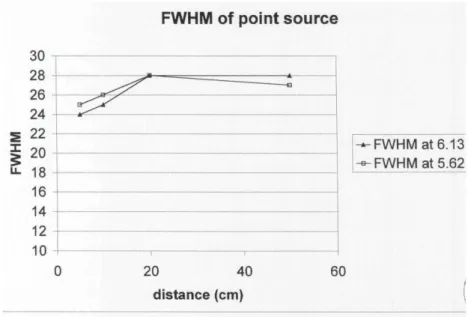
Figure 10 reports the Full Width Half Maximum (FWHM) experimental values measured for the 6.13 MeV photopeak and for the single annihilation escape peak.
The single and double annhilation escape can also be taken into account for the detection of 16N, due to the fact that they are an intrinsic characteristic of the photon detection process. The single escape in particular, as can be seen in Figure 6, is well resolved and can be efficiently used, in addition to the 6.13 Me V photopeak. For the detector under examination the experimentally determined ratio (area of photopeak)/(area of single escape) is 0.82 ± 0.1.
A measure of the total area under the double escape, single escape and photopeak was evaluated, and the value (area of three peaks)/(area of photopeak) was 4.95 + 0.6.
20
In order to transform the point source full energy peak efficiency into real efficiency for the detector assembly faced to the stearn pipe, a model for gamma detection from an extended object must be applied. In the present case two different simplified models (A and B) have been calculated.
Model A
Let us suppose that the gamma emission is detected only within a cone with apex in the center of the face opposed to the detection face, and with generatrix tangent to the circular border of the detector (see Figure 11).
Figure 11
The intersection of the cone with the secondary circuit steam pipe is an "intersection solid" with equation x2 –z2 -(z tg )2 –d2 -2dz – R2=0 (where d is the distance of the center of the pipe from the center of the detector, R the inner radius of the pipe, 2the apex angle of the cone), and is shown in Figure 12.
21 Figure 12
If we transform the "intersection solid" as a series of planes parallel to the detection face of the detector (Figure 11), we can apply to each of the planes the formula for the sodium iodide efficiency of a rectangular source 3, which is
E= Ep + L (a 2
+b2)/12r2 + M (a4+10/9 a2b2 + b4)/80 r4
Where E is source intrinsic efficiency at distance h on the detector axis, Ep is the isotropic point
source intrinsic efficiency at distance h on the detector axis, L and M are tabulated correction factors, r the radius of the detector, a is the lenght and b the width of the source.
The values Ep, L and M were interpolated for any computed distance, and a sum of each plane
efficiency was made. The calculation process was iteratively repeated increasing the number of intersection planes, so obtaining a numerical integration, up to the point in which two successive calculations gave a difference lower of l%.
The final source intrinsic efficiency was multiplied for the peak-to-total ratio of the photofraction at 6.13 Me V (see Figure 9) in order to obtain the source full energy
The total volume of the intersection solid was found 150.6 dm3, and the source full energy peak. efficiency was found to be 8.01.10-5 This efficiency must be multiplied for 0.62 (factor of real-to-ideal efficiency, see above), and must be rescaled for the absorption in the wall of the reactor pipe and in the glass wool insulating mantle. An evaluation of the absorption gave a value of 0.92 for glass wool and 0.68 for steel wall.
22
The absorption corrected efficiency is then 3.1. 10-5, and the expression for detected activity is
DA = TA.Y.3.1.10-5.150.6/TV = 4.7. 10-3 .TA/TV .Y
Where DA is the detected activity in cps, TA is the total activity in the secondary circuit (in Becquerel) Y is the yield of 6.13 MeV gamma line , TV is the total volume of the secondary circuit, in dm3.
Model B
Let us suppose that the gamma emission is produced from a linear source much longer than the distance from the detector to the center of the source.
Let us divide the lenght of the detector in a series of slices; each of the slice, due to the fact that is laterally shielded, can only detect a fraction of the total source (see Figure 13).
Figure 13
The efficiency for each slice is ESsi =K/aihi (arctan (ai/hi)), where hi is the distance of the slice i from
the center of the source, ai is the lenght of the source detected by the slice i, and K is a costant proportional to the activity per meter.
For a point source with the same activity, the efficiency for the slice i takes the form EPsi = K/hi 2
23 By performing the sum i ESsi and the sumi EPsi , and increasing the lenght of the source and the
number of summation steps up to reach a convergence within l% (source lenght 5.03 meters), we obtain for i ESsi the value 15.35 10
-2
and for i EPsi the value 0.875.
The ratio 15.35 10-2 /0.875= 0.175 represent the va1ue to multiply for the linear source lenght (5 .03 meters) after convergence, for obtaining the activity of an equivalent point source with the same efficiency.
The efficiency of a 3"x3" ideal detector from a point source is 8.6 l0-5, which must be multiplied , as with model A, for the real-to-ideal correction factor of 0.62, and for the absorption correction factors of 0.92 for glass wool and 0.68 for steel wall. The final efficiency gives the value of 3.3 10-5 and the expression for detected activity is
DA = 4.3. 10-3 .TA/TV .Y
where DA is the detected activity in cps, TA is the total activity in the secondary circuit, in Becquerel, Y is the yield of 6. I 3 MeV gamma line , TV is the total volume of the secondary circuit, in dm3 The obtained value is in excellent agreement with the Model A.
Conclusions
The uncertainty on the experimental obtained efficiency value is mainly dominated from the error in the reference 238Pu/13C source, and is estimated of ± 5%. The calibrated point source was particularly useful in the characterization of the annealing behaviour of the detector, and in the absolute quantification of the detector efficiency. Although the performance of the detector is lowered by the annealing process, this process was considered essential to stabilize the detector characteristics. Infact the stability of the detector is considered much more important than the absolute sensitivity for its use as leakage monitor.
The quantification of dynamic flow preparation of 16N by use of the nuclear reactor was affected by an uncertainty that was extimated to about ± 30%; for this reason the absolute value of efficiency obtained with the reactor method was rescaled with an empirical factor, by using the point source as "certified value". Many diffrent techniques have been developed and tested in order to increase the sensitivity of primary coolant leakage in nuclear power plants and consequntly the their operative safety 4-12 ; the monitoring of 16N is still considered one of the most affordable and precise methods to on-line detect a coolant leakage from the prirnary circuit.
24
In spite of the higher complexity and lesser precision, the dynamic flow preparation of 16N by use of the nuclear reactor provides a calibration in real operative conditions, including the radiation background. This method can also test the detector under conditions of simulated real primary circuit leakage.
As an example, a simulated low leakage was simulated with a low, constant air flux into the irradiation circuit; a break in the primary circuit was simulated by pumping an high pure O2 high flux,
and so on. A sudden variation of radioactive gas can also characterize the behaviour of the detector to radioactivity transients, and describe the time "readiness" of the whole detection apparatus.
As an example of obtainable sensitivity for the detector, by using B model, let us suppose for the pipe a total lenght of 100 m, a corresponding total volume of 1472 dm3 for the secondary loop, and a total activity of 1 Ci of 16N in the secondary pipe. In such very negligible leakage, by summing the area of photopeak and of single and double escape peaks, a count of 200 counts over background is reached in less than 8 minutes. with a statistical error at a confidence level of 95%. All the obtained certifications were fully accepted by the manufacturer of the detector that required the certification (Silena, Italy) and from the technical committee of the nuclear power plant, and the detector was regularly installed in the steam circuit.
The proposed protocol can also be used for testing the multichannel and/or other electronic instrumentation for nuclear industry, as it provides an "in-field" test in dynamic flow conditions, and the same operative concept can be proposed and extended to different isotopes monitoring and characterization.
Due to the modular characteristics of the irradiation loop, the same principle can be applied to different reactors (as an example, to TRIGA reactor), with different neutron energy and flux, in order to realize characterization circuit in different operative conditions, in different geometries, by using different gases, or by using water in the irradiation loop to realistically simulate primary steam circuit fluid dynamics.
25
References
1. System Design Manual – Plant Radiation Monitoring System [KRT] - EYTS/2007/FR/0042 rev B1
2. Applicability of the leak before break concept, IAEA-TECDOC-710, June 1993
3. Grosjean CC, Bossaert W, Table of absolute detection efficiencies of cylindrical scintillation gamma-ray detectors: including correction coefficients to take into account the finite extension of plane sources, Editore Computing Laboratory of the University of Ghent, 1965 4. Nathwani JS et al. Ontario Hydro's LBB Approach, Nuclear Engineering and Design 111
(1989), pp. 85-107
5. Orlenkov IS, Moskvin LN, Primary-to-secondary leak monitoring using information obtained from measurement of reference radionuclides in NPP water, Radiochemistry (2010) 52: 607 6. Kasai Y, Shimanskiy S, Naoi Y, Kanazawa Y, (2004) Leak Detection in the Primary Reactor
Coolant Piping of Nuclear Power Plant by Applying Beam-Microphone Technology, Journal of Nuclear Science and Technology, 41:3,359-366
7. Kussmaul K., German basic safety concept rules out possibility of catastrophic failure, Nucl. Eng. Int. (1984) 41-46
8. Redefining the large break LOCA: technical issues and its implications, Unclassified, NEA/CSNI/R(2003)17/Vol 2
9. Kukita K, Tasaka K, Asaka H, Yonomoto T, Kumama H, The effects of break location on PWR small break LOCA: Experimental study at the ROSA-IV LSTF, Nuclear Engineering and Design, 122:255–262, 1990
10. Incorporation of advanced accident analysis methodology into safety analysis reports. Technical report, International Atomic Energy Agency, IAEA-TECHDOC-1351, 2003. 11. Kim MC, Seong PH, A method for identifying instrument faults innuclear power plants
possibly leading to wrong situation assessment, Reliability Engineering and System Safety, 93:316–324, 2008
12. Lee PJ, Lambert MF, Simpson AR, Vítkovsk JP, Liggett J, Experimental verification of the frequency response method for pipeline leak detection, Journal of Hydraulic Research, (2006),, Vol. 44, No. 5, 693–707
ENEA
Servizio Promozione e Comunicazione
www.enea.it
Stampa: Laboratorio Tecnografico ENEA - C.R. Frascati maggio 2017