Journal of Physics G: Nuclear and Particle Physics
PAPER • OPEN ACCESS
Technical design report for the
Barrel DIRC
detector
*
To cite this article: B Singh et al 2019 J. Phys. G: Nucl. Part. Phys. 46 045001
View the article online for updates and enhancements.
Recent citations
Spectroscopic properties of D-meson using screened potential
Vikas Patel et al
-DIRC: Internally reflecting imaging Cherenkov detectors
B. Ratcliff and J. Va’vra
-Performance of the most recent MCP-PMTs
M. Böhm et al
-Technical design report for the PANDA
Barrel DIRC detector
*
B Singh
1, W Erni
2, B Krusche
2, M Steinacher
2, N Walford
2,
B Liu
3, H Liu
3, Z Liu
3, X Shen
3, C Wang
3, J Zhao
3,
M Albrecht
4, T Erlen
4, F Feldbauer
4, M Fink
4, M Fritsch
4,
J Haase
4, F H Heinsius
4, T Held
4, T Holtmann
4, I Keshk
4,
H Koch
4, B Kopf
4, M Kuhlmann
4, M Kümmel
4, S Leiber
4,
M Mikirtychyants
4, P Musiol
4, A Mustafa
4, M Pelizäus
4,
A Pitka
4, J Pychy
4, M Richter
4, C Schnier
4, T Schröder
4,
C Sowa
4, M Steinke
4, T Triffterer
4, U Wiedner
4, M Ball
5,
R Beck
5, C Hammann
5, B Ketzer
5, M Kube
5, P Mahlberg
5,
M Rossbach
5, C Schmidt
5, R Schmitz
5, U Thoma
5, M Urban
5,
D Walther
5, C Wendel
5, A Wilson
5, A Bianconi
6,
M Bragadireanu
7, D Pantea
7, B Patel
8, W Czyzycki
9,
M Domagala
9, G Filo
9, J Jaworowski
9, M Krawczyk
9,
E Lisowski
9, F Lisowski
9, M Micha
łek
9, P Pozna
ński
9,
J P
łażek
9, K Korcyl
10, A Kozela
10, P Kulessa
10,
P Lebiedowicz
10, K Pysz
10, W Schäfer
10, A Szczurek
10,
T Fiutowski
11, M Idzik
11, B Mindur
11, K Swientek
11,
J Biernat
12, B Kamys
12, S Kistryn
12, G Korcyl
12,
W Krzemien
12, A Magiera
12, P Moskal
12, A Pyszniak
12,
Z Rudy
12, P Salabura
12, J Smyrski
12, P Strzempek
12,
A Wronska
12, I Augustin
13, R Böhm
13, I Lehmann
13,
D Nicmorus Marinescu
13, L Schmitt
13, V Varentsov
13, A Ali
14,
M Al-Turany
14, A Belias
14, H Deppe
14, N Divani Veis
14,
R Dzhygadlo
14, H Flemming
14, A Gerhardt
14, K Götzen
14,
A Gromliuk
14, L Gruber
14, R Hohler
14, G Kalicy
14,
R Karabowicz
14, R Kliemt
14, M Krebs
14, U Kurilla
14,
D Lehmann
14, S Löchner
14, J Lühning
14, U Lynen
14,
F Nerling
14, H Orth
14, M Patsyuk
14, K Peters
14, T Saito
14,
G Schepers
14, C J Schmidt
14, C Schwarz
14,
J Schwiening
14,66, A Täschner
14, M Traxler
14, C Ugur
14,
B Voss
14, P Wieczorek
14, A Wilms
14, M Zühlsdorf
14,
V Abazov
15, G Alexeev
15, V A Are
fiev
15, V Astakhov
15,
M Yu Barabanov
15, B V Batyunya
15, Y Davydov
15,
V Kh Dodokhov
15, A Efremov
15, A Fechtchenko
15,
Journal of Physics G: Nuclear and Particle Physics J. Phys. G: Nucl. Part. Phys. 46(2019) 045001 (155pp) https://doi.org/10.1088/1361-6471/aade3d
* The use of registered names, trademarks, etc in this publication does not imply, even in the absence of specific statement, that such names are exempt from the relevant laws and regulations and therefore free for general use.
A G Fedunov
15, A Galoyan
15, S Grigoryan
15,
E K Koshurnikov
15, Y Yu Lobanov
15, V I Lobanov
15,
A F Makarov
15, L V Malinina
15, V Malyshev
15,
A G Olshevskiy
15, E Perevalova
15, A A Piskun
15,
T Pocheptsov
15, G Pontecorvo
15, V Rodionov
15, Y Rogov
15,
R Salmin
15, A Samartsev
15, M G Sapozhnikov
15,
G Shabratova
15, N B Skachkov
15, A N Skachkova
15,
E A Strokovsky
15, M Suleimanov
15, R Teshev
15,
V Tokmenin
15, V Uzhinsky
15, A Vodopianov
15,
S A Zaporozhets
15, N I Zhuravlev
15, A Zinchenko
15,
D Branford
16, D Glazier
16, D Watts
16, M Böhm
17, A Britting
17,
W Eyrich
17, A Lehmann
17, M Pfaf
finger
17, F Uhlig
17,
S Dobbs
18, K Seth
18, A Tomaradze
18, T Xiao
18, D Bettoni
19,
V Carassiti
19, A Cotta Ramusino
19, P Dalpiaz
19, A Drago
19,
E Fioravanti
19, I Garzia
19, M Savrie
19, V Akishina
20,
S Gorbunov
20, I Kisel
20, G Kozlov
20, M Pugach
20, M Zyzak
20,
P Gianotti
21, C Guaraldo
21, V Lucherini
21, A Bersani
22,
G Bracco
22, M Macri
22, R F Parodi
22, K Biguenko
23,
K T Brinkmann
23, V Di Pietro
23, S Diehl
23, V Dormenev
23,
M Düren
23, E Etzelmüller
23, K Föhl
23, M Galuska
23, E Gutz
23,
C Hahn
23, A Hayrapetyan
23, M Kesselkaul
23, K Kreutzfeldt
23,
W Kühn
23, T Kuske
23, J S Lange
23, Y Liang
23, V Metag
23,
M Moritz
23, M Nanova
23, R Novotny
23, T Quagli
23, S Reiter
23,
A Riccardi
23, J Rieke
23, C Rosenbaum
23, M Schmidt
23,
R Schnell
23, H Stenzel
23, U Thöring
23, M N Wagner
23,
T Wasem
23, B Wohlfahrt
23, H G Zaunick
23,
E Tomasi-Gustafsson
24, D Ireland
25, G Rosner
25, B Seitz
25,
P N Deepak
26, A Kulkarni
26, A Apostolou
27, M Babai
27,
M Kavatsyuk
27, P J Lemmens
27, M Lindemulder
27,
H Loehner
27, J Messchendorp
27, P Schakel
27, H Smit
27,
M Tiemens
27, J C van der Weele
27, R Veenstra
27, S Vejdani
27,
S Vejdani
27, K Dutta
28, K Kalita
28, A Kumar
29, A Roy
29,
H Sohlbach
30, M Bai
31, L Bianchi
31, M Büscher
31, L Cao
31,
A Cebulla
31, R Dosdall
31, A Erven
31, V Fracassi
31,
A Gillitzer
31, F Goldenbaum
31, D Grunwald
31, A Herten
31,
Q Hu
31, L Jokhovets
31, G Kemmerling
31, H Kleines
31, A Lai
31,
A Lehrach
31, R Nellen
31, H Ohm
31, S Orfanitski
31,
D Prasuhn
31, E Prencipe
31, J Pütz
31, J Ritman
31,
E Rosenthal
31, S Schadmand
31, T Sefzick
31, V Serdyuk
31,
G Sterzenbach
31, T Stockmanns
31, P Wintz
31, P Wüstner
31,
H Xu
31, S Li
32, Z Li
32, Z Sun
32, H Xu
32, V Rigato
33,
L Isaksson
34, P Achenbach
35, A Aycock
35, O Corell
35,
A Denig
35, M Distler
35, M Hoek
35, A Karavdina
35, W Lauth
35,
Z Liu
35, H Merkel
35, U Müller
35, J Pochodzalla
35, S Sanchez
35,
S Schlimme
35, C S
fienti
35, M Thiel
35, H Ahmadi
36,
S
Ahmed
36, S Bleser
36, L Capozza
36, M Cardinali
36,
A Dbeyssi
36, M Deiseroth
36, A Ehret
36, B Fröhlich
36,
D Kang
36, D Khaneft
36, R Klasen
36, H H Leithoff
36, D Lin
36,
F Maas
36, S Maldaner
36, M Martínez
36, M Michel
36,
M C Mora Espí, C Morales Morales
36, C Motzko
36, O Noll
36,
S P
flüger
36, D Rodríguez Piñeiro
36, A Sanchez-Lorente
36,
M Steinen
36, R Valente
36, M Zambrana
36, I Zimmermann
36,
A Fedorov
37, M Korjik
37, O Missevitch
37, A Balashoff
38,
A Boukharov
38, O Malyshev
38, I Marishev
38, P Balanutsa
39,
V Balanutsa
39, V Chernetsky
39, A Demekhin
39,
A Dolgolenko
39, P Fedorets
39, A Gerasimov
39,
V Goryachev
39, V Chandratre
40, V Datar
40, D Dutta
40, V Jha
40,
H Kumawat
40, A K Mohanty
40, A Parmar
40, A K Rai
40, B Roy
40,
G Sonika
40, C Fritzsch
41, S Grieser
41, A K Hergemöller
41,
B Hetz
41, N Hüsken
41, A Khoukaz
41, J P Wessels
41,
K Khosonthongkee
42, C Kobdaj
42, A Limphirat
42,
P Srisawad
42, Y Yan
42, E Antokhin
43, A Yu Barnyakov
43,
M Barnyakov
43, K Beloborodov
43, V E Blinov
43,
V S Bobrovnikov
43, I A Kuyanov
43, K Martin
43, A P Onuchin
43,
S Pivovarov
43, E Pyata
43, S Serednyakov
43, A Sokolov
43,
Y Tikhonov
43, A E Blinov
44, S Kononov
44, E A Kravchenko
44,
E Atomssa
45, R Kunne
45, D Marchand
45, B Ramstein
45,
J van de Wiele
45, Y Wang
45, G Boca
46, S Costanza
46,
P Genova
46, P Montagna
46, A Rotondi
46, M Bodlak
47,
M Finger
47, M Finger
47, A Nikolovova
47, M Pesek
47,
M Peskova
47, M Pfeffer
47, I Prochazka
47, M Slunecka
47,
P Gallus
48, V Jary
48, J Novy
48, M Tomasek
48, M Virius
48,
V Vrba
48, V Abramov
49, N Belikov
49, S Bukreeva
49,
A Davidenko
49, A Derevschikov
49, Y Goncharenko
49,
V Grishin
49, V Kachanov
49, V Kormilitsin
49, A Levin
49,
Y Melnik
49, N Minaev
49, V Mochalov
49, D Morozov
49,
L Nogach
49, S Poslavskiy
49, A Ryazantsev
49, S Ryzhikov
49,
P Semenov
49, I Shein
49, A Uzunian
49, A Vasiliev
49,
A Yakutin
49, U Roy
50, B Yabsley
51, S Belostotski
52,
G Gavrilov
52, A Izotov
52, S Manaenkov
52, O Miklukho
52,
D Veretennikov
52, A Zhdanov
52, K Makonyi
53, M Preston
53,
P E Tegner
53, D Wölbing
53, T Bäck
54, B Cederwall
54,
S Godre
55, F Balestra
56, F Iazzi
56, R Introzzi
56, A Lavagno
56,
J Olave
56, A Amoroso
57, M P Bussa
57, L Busso
57,
M Destefanis
57, L Fava
57, L Ferrero
57, M Greco
57, J Hu
57,
L Lavezzi
57, M Maggiora
57, G Maniscalco
57, S Marcello
57,
S Sosio
57, S Spataro
57, D Calvo
58, S Coli
58, P De Remigis
58,
A Filippi
58, G Giraudo
58, S Lusso
58, G Mazza
58, M Mignone
58,
A Rivetti
58, R Wheadon
58, R Birsa
59, F Bradamante
59,
A Bressan
59, A Martin
59, H Calen
60, W Ikegami Andersson
60,
T Johansson
60, A Kupsc
60, P Marciniewski
60,
M Papenbrock
60, J Pettersson
60, K Schönning
60, M Wolke
60,
B Galnander
61, J Diaz
62, V Pothodi Chackara
63, A Chlopik
64,
G Kesik
64, D Melnychuk
64, B Slowinski
64, A Trzcinski
64,
M Wojciechowski
64, S Wronka
64, B Zwieglinski
64, P Bühler
65,
J Marton
65, D Steinschaden
65, K Suzuki
65, E Widmann
65,
S Zimmermann
65and J Zmeskal
651
Aligarth Muslim University, Physics Department, Aligarth, India
2
Universität Basel, Basel, Switzerland
3
Institute of High Energy Physics, Chinese Academy of Sciences, Beijing, People’s Republic of China
4
Ruhr-Universität Bochum, Institut für Experimentalphysik I, Bochum, Germany
5Rheinische Friedrich-Wilhelms-Universität Bonn, Bonn, Germany 6
Universitá di Brescia, Brescia, Italy
7
Institutul National de C&D pentru Fizica si Inginerie Nucleara‘Horia Hulubei’, Bukarest-Magurele, Romania
8
P.D. Patel Institute of Applied Science, Department of Physical Sciences, Changa, India
9
University of Technology, Institute of Applied Informatics, Cracow, Poland
10
IFJ, Institute of Nuclear Physics PAN, Cracow, Poland
11
AGH, University of Science and Technology, Cracow, Poland
12
Instytut Fizyki, Uniwersytet Jagiellonski, Cracow, Poland
13
FAIR, Facility for Antiproton and Ion Research in Europe, Darmstadt, Germany
14
GSI Helmholtzzentrum für Schwerionenforschung GmbH, Darmstadt, Germany
15
Veksler-Baldin Laboratory of High Energies(VBLHE), Joint Institute for Nuclear Research, Dubna, Russia
16
University of Edinburgh, Edinburgh, United Kingdom
17
Friedrich Alexander Universität Erlangen-Nürnberg, Erlangen, Germany
18
Northwestern University, Evanston, United States of America
19
Universitá di Ferrara and INFN Sezione di Ferrara, Ferrara, Italy
20
Frankfurt Institute for Advanced Studies, Frankfurt, Germany
21
INFN Laboratori Nazionali di Frascati, Frascati, Italy
22
INFN Sezione di Genova, Genova, Italy
23
Justus Liebig-Universität Gießen II. Physikalisches Institut, Gießen, Germany
24
IRFU, CEA, Université Paris-Saclay, Gif-sur-Yvette Cedex, France
25
University of Glasgow, Glasgow, United Kingdom
26
Birla Institute of Technology and Science, Pilani, K K Birla Goa Campus, Goa, India
27KVI-Center for Advanced Radiation Technology(CART), University of Groningen,
Groningen, Netherlands
28
Gauhati University, Physics Department, Guwahati, India
29
Indian Institute of Technology Indore, School of Science, Indore, India
30
Fachhochschule Südwestfalen, Iserlohn, Germany
31
Forschungszentrum Jülich, Institut für Kernphysik, Jülich, Germany
32Chinese Academy of Science, Institute of Modern Physics, Lanzhou, People’s
Republic of China
33
INFN Laboratori Nazionali di Legnaro, Legnaro, Italy
34
Lunds Universitet, Department of Physics, Lund, Sweden
35
Johannes Gutenberg-Universität, Institut für Kernphysik, Mainz, Germany
36
Helmholtz-Institut Mainz, Mainz, Germany
37
Research Institute for Nuclear Problems, Belarus State University, Minsk, Belarus
38
39
Institute for Theoretical and Experimental Physics, Moscow, Russia
40
Nuclear Physics Division, Bhabha Atomic Research Centre, Mumbai, India
41
Westfälische Wilhelms-Universität Münster, Münster, Germany
42
Suranaree University of Technology, Nakhon Ratchasima, Thailand
43
Budker Institute of Nuclear Physics, Novosibirsk, Russia
44
Novosibirsk State University, Novosibirsk, Russia
45
Institut de Physique Nucléaire, CNRS-IN2P3, Univ. Sud, Université Paris-Saclay, F-91406, Orsay cedex, France
46
Dipartimento di Fisica, Universitá di Pavia, INFN Sezione di Pavia, Pavia, Italy
47
Charles University, Faculty of Mathematics and Physics, Prague, Czechia
48Czech Technical University, Faculty of Nuclear Sciences and Physical Engineering,
Prague, Czechia
49
Institute for High Energy Physics, Protvino, Russia
50
Sikaha-Bhavana, Visva-Bharati, WB, Santiniketan, India
51
University of Sidney, School of Physics, Sidney, Australia
52
National Research Centre‘Kurchatov Institute’ B. P. Konstantinov Petersburg Nuclear Physics Institute, Gatchina, St. Petersburg, Russia
53Stockholms Universitet, Stockholm, Sweden 54
Kungliga Tekniska Högskolan, Stockholm, Sweden
55
Veer Narmad South Gujarat University, Department of Physics, Surat, India
56
Politecnico di Torino and INFN Sezione di Torino, Torino, Italy
57
Universitá di Torino and INFN Sezione di Torino, Torino, Italy
58
INFN Sezione di Torino, Torino, Italy
59
Universitá di Trieste and INFN Sezione di Trieste, Trieste, Italy
60
Uppsala Universitet, Institutionen för fysik och astronomi, Uppsala, Sweden
61
The Svedberg Laboratory, Uppsala, Sweden
62Instituto de Física Corpuscular, Universidad de Valencia-CSIC, Valencia, Spain 63
Sardar Patel University, Physics Department, Vallabh Vidynagar, India
64
National Centre for Nuclear Research, Warsaw, Poland
65
Österreichische Akademie der Wissenschaften, Stefan Meyer Institut für Subatomare Physik, Wien, Austria
E-mail:[email protected]
Received 17 November 2017, revised 13 April 2018 Accepted for publication 31 August 2018
Published 28 February 2019 Abstract
ThePANDA(anti-Proton ANnihiliation at DArmstadt) experiment will be one of
the fourflagship experiments at the new international accelerator complex FAIR (Facility for Antiproton and Ion Research) in Darmstadt, Germany.PANDA will address fundamental questions of hadron physics and quantum chromodynamics using high-intensity cooled antiproton beams with momenta between 1.5 and 15 GeV/c and a design luminosity of up to 2× 1032cm−2s−1. Excellent particle identification (PID) is crucial to the success of the PANDA physics program. Hadronic PID in the barrel region of the target spectrometer will be performed by a 66
Author to whom any correspondence should be addresed.
Original content from this work may be used under the terms of theCreative Commons Attribution 3.0 licence. Any further distribution of this work must maintain attribution to the author(s) and the title of the work, journal citation and DOI.
fast and compact Cherenkov counter using the detection of internally reflected Cherenkov light(DIRC) technology. It is designed to cover the polar angle range from 22° to 140° and will provide at least 3standard deviations (s.d.) π/K separation up to 3.5 GeV/c, matching the expected upper limit of the final state kaon momentum distribution from simulation. This documents describes the technical design and the expected performance of the PANDA Barrel DIRC detector. The design is based on the successful BaBar DIRC with several key improvements. The performance and system cost were optimized in detailed detector simulations and validated with full system prototypes using particle beams at GSI and CERN. Thefinal design meets or exceeds the PID goal of clean π/K separation with at least 3 s.d. over the entire phase space of charged kaons in the Barrel DIRC.
Keywords: particle identification, ring imaging Cherenkov detector, DIRC counter, PANDA experiment, hadron physics
(Some figures may appear in colour only in the online journal) 1. Executive summary
1.1. The P̅ ANDA experiment
The PANDA experiment [1] will be one of the four flagship experiments at the new
inter-national accelerator complex FAIR(Facility for Antiproton and Ion Research) in Darmstadt, Germany.PANDAwill perform unique experiments using the high-quality antiproton beam with momenta in the range of 1.5 GeV/c to 15 GeV/c, stored in the HESR (High Energy Storage Ring), to explore fundamental questions of hadron physics in the charmed and multi-strange hadron sector and deliver decisive contributions to the open questions of quantum chromodynamics (QCD). The scientific program ofPANDA [2] includes hadron spectrosc-opy, properties of hadrons in matter, nucleon structure, and hypernuclei. The cooled anti-proton beam colliding with afixed proton or nuclear target will allow hadron production and formation experiments with a luminosity of up to 2×1032cm−2s−1. Excellent particle identification (PID) is crucial to the success of thePANDA physics program.
1.2. Particle identification in P̅ ANDA
ThePANDA PID system comprises a range of detectors using different technologies. Dedicated
PID devices, such as several time-of-flight (TOF) and Cherenkov counters and a Muon detection system[3], are combined with PID information delivered by the micro vertex detector [4] and the Straw Tube Tracker[5] as well as by the Electromagnetic Calorimeter (EMC) [6].
While the specific energy loss measurements from the PANDA tracking detectors, in combination with the TOF information, provideπ/K separation at low momentum, dedicated hadronic PID systems are required for the positive identification of kaons with higher momentum(p >1 GeV/c) and for the suppression of large pionic backgrounds. Two ring imaging Cherenkov (RICH) counters using the detection of internally reflected Cherenkov light(DIRC) principle [7–9] in the target spectrometer (TS) and an aerogel RICH counter in the forward spectrometer(FS) will provide this charged hadron PID.
The DIRC concept was introduced and successfully used by the BaBar experiment[10] where it provided excellentπ/K separation up to 4.2 GeV/c and proved to be robust and easy
to operate. In PANDA the Barrel DIRC, modeled after the BaBar DIRC, will surround the interaction point at a distance of about 50 cm and cover the central region of 22°<θ<140° while the novel Endcap Disc DIRC[11] will cover the smaller forward angles, 5°<θ<22° and 10°<θ<22° in the vertical and horizontal direction, respectively.
1.3. The P̅ ANDA Barrel DIRC
The Barrel DIRC design described in this report will provide a clean separation of charged pions and kaons with 3 standard deviations(s.d.) or more in the range of 0.5–3.5 GeV/c. The scientific merit of the Barrel DIRC is that the PID performance enables a wide range of physics measurements inPANDA with kaons in thefinal state, i.e. the study of light hadron reactions, charmed baryons, charmonium spectroscopy, and open charm events.
The design concept is based on the successful BaBar DIRC[10] and key results from the R&D for the SuperB FDIRC[12]. The main design difference compared to the BaBar DIRC, the replacement of the large water tank expansion volume(EV) by 16 compact prisms, is due to the fact that the plans for the magnet and the upstream endcap of thePANDAdetector did not allow the DIRC bars to penetrate the iron, requiring a small EV that can be placed inside the already crowdedPANDA detector volume. This compact EV in turn meant that focusing optics and smaller sensor pixels are needed to keep the Cherenkov angle resolution similar to the performance obtained by the BaBar DIRC.
In thePANDABarrel DIRC baseline design the circular cross section of the barrel part is approximated by a hexadecagon. Each of the 16 flat sections contains three fused silica radiator bars (17×53×2400 mm3). Cherenkov photons, produced along the charged par-ticle track in the bar, are guided inside the radiator via total internal reflection. A flat mirror is attached to the forward end of the bar to reflect photons towards the read out end, where they are focused by a multi-component spherical lens on the back of a 30 cm deep solid fused silica prism, serving as EV.
An array of lifetime-enhanced microchannel plate photomultiplier tubes (MCP-PMTs) [13], each with 8×8 pixels of about 6.5×6.5 mm2size, is used to detect the photons and measure their arrival time on a total of about 11 300 pixels with a precision of 100 ps or better in the magneticfield of approximately 1 T.
The sensors are read out by an updated version of the trigger and readout board(TRB) [14], developed for the high-acceptance dielectron spectrometer (HADES) experiment [15], in combination with the PADIWA front-end amplification and discrimination card [16], mounted directly on the MCP-PMTs. This FPGA-based system provides measurements of both the photon arrival time and time-over-threshold (TOT), which is related to the pulse height of the analog signal and can be used to monitor the sensor performance and to perform time-walk corrections to achieve the required precision of the photon timing.
The focusing optics has to produce aflat image to match the shape of the back surface of the fused silica prism. This is achieved by a combination of focusing and defocusing elements in a spherical triplet lens made from one layer of lanthanum crown glass(NLaK33, refractive index n=1.786 for λ=380 nm) between two layers of synthetic fused silica (n=1.473 for λ=380 nm). Such a 3-layer lens works without any air gaps, minimizing the photon loss that would otherwise occur at the transition from the lens to the EV.
The mechanical system is modular with components made of aluminum alloy and carbon-fiberreinforced polymer (CFRP). The optical components are placed in light-tight CFRP con-tainers that are installed in thePANDAdetector by sliding them on rails into slots in two rings which are attached to the main central support beams. Boil-off dry nitrogenflows through the CFRP containers to remove moisture and residue from outgassing. The entire readout unit,
comprising the prisms, sensors, and electronics, can be detached from thePANDAdetector to facilitate access to the tracking systems during scheduled extended shutdowns.
Industrial fabrication of the fused silica radiators remains a significant technological challenge, just as it was during the construction of the BaBar DIRC and the BelleII TOP [17]. An excellent surface polish with an RMS roughness of 10Å or better is needed for efficient photon transport since Cherenkov photons are internally reflected up to 400 times before exiting the bar. The radiator surfaces have to be perpendicular to each other within 0.25 mrad to preserve the magnitude of the Cherenkov angle during these reflections. Due to the tight optical and mechanical tolerances the price of radiator fabrication is, together with the price of the photon detectors, the dominant contribution to the Barrel DIRC construction cost.
A substantial reduction of the radiator fabrication cost is achieved by increasing the width of the fused silica bars by 50% compared to the BaBar DIRC.
A further significant cost reduction may be possible if the three radiator bars per section are replaced by one 16 cm wide plate since even fewer pieces would have to be produced. However, although a design with an even wider plate(with a width of 45 cm) is being built for the BelleII experiment, so far the PID performance of a Barrel DIRC design with wide plates has not been validated experimentally. Therefore, until such an experimental validation is achieved, the wide plates remain only as an alternative cost-saving design option to the narrow bar geometry baseline design.
The use of legacy detector components as a cost-saving measure was investigated in 2013 when the SLAC National Accelerator Laboratory issued a call for proposals for reuse of the BaBar DIRC bar boxes. ThePANDA collaboration submitted a letter of interest and detailed proposal for using three BaBar DIRC bar boxes, which, after disassembly, could have yielded all the narrow radiator bars needed for thePANDABarrel DIRC. The formal review by SLAC and US Department of Energy(DOE), Office of High Energy Physics (OHEP), decided in 2014 that the reuse of the BaBar DIRC bar boxes would only be granted to experiments that keep the bar boxes intact. This was not an option forPANDA since the length of the BaBar DIRC bar boxes is about 490 cm, twice the length of thePANDA Barrel DIRC.
1.4. Simulation and prototyping
A detailed physical simulation of the PANDA Barrel DIRC was developed in the PAN-DARoot framework[18,19], which uses the virtual Monte Carlo (VMC) approach to easily switch between Geant3 and Geant4 [20] for systematic studies. The simulation is tuned to include measured values for the sensor quantum and collection efficiency and the timing resolution[13]. It includes the coefficient of total internal reflection of DIRC radiator bars as a function of photon energy [21], the bulk transmission of bars, glue, and lenses, the wave-length-dependent refractive indices of fused silica, NLaK33, and the photocathode, as well as the reflectivity of the forward mirrors. Background from hadronic interaction and delta electrons is simulated as well as contributions from MCP-PMT dark noise and charge sharing between anode pads. Additional simulation tools employed during the R&D phase include Zemax[22], used primarily in the design of the focusing optics, and DircProp, a stand-alone ray-tracing package designed at GSI, for the development of prototype configurations.
For the purpose of design evaluation the single photon Cherenkov angle resolution(SPR) and the photon yield were selected as figures of merit. These two quantities allow a com-parison of different design options to the performance of prototypes in test beams and to published results for the BaBar DIRC and other RICH counters. A fast reconstruction method based on lookup-tables(LUT), similar to the approach used for the BaBar DIRC, was utilized to determine the SPR and photon yield for a wide range of particle angles and momenta for
each simulated design with narrow bars. For the evaluation of the design option with wide plates an alternative reconstruction algorithm was developed[23], the so-called time-based imaging method, similar to the approach used by the BelleII TOP [24].
In the process of optimizing the design of the PANDA Barrel DIRC for cost and performance many different design aspects were tested in simulations. These include the thickness and width of the radiators, the number of bars per sector, the material and shape of the focusing lenses, the material, shape, and size of the EV, and the sensor layout on the focal plane[25]. The SPR and photon yield were determined for each configuration and evaluated as a function of momentum, polar and azimuthal angle for the entire PANDA phase space. The simulation effort identified several designs that meet or exceed thePANDA PID per-formance requirements for the entire kaon phase space.
1.5. Design validation
A number of the most promising design elements were implemented in prototypes and tested under controlled conditions in a dedicated optics laboratory or with particle beams.
A total of more than 30 radiator prototypes, narrow bars as well as wide plates, were produced by eight manufacturers using different materials and fabrication processes. The goal was to identify companies capable of producing high-quality radiators for the full-scale
PANDA Barrel DIRC production. The radiator surface properties were measured by
internally reflecting laser beams of different wavelengths to determine the coefficient of internal reflection and to study subsurface damage effects. The bar angles were measured using an autocollimator. The results show that several of the prototype manufactures are able to produce high-quality bars or plates that meet the specifications.
A series of increasingly complexPANDABarrel DIRC system prototypes were tested in particle beams at GSI and CERN from 2011 to 2016 to determine the PID performance and to validate the simulation results. The prototypes all featured a dark box containing a radiator bar or plate coupled via optional focusing to an EV equipped with a photon detector array on the image plane. The sensors were read out by a TRB in combination with an amplification and discrimination card mounted directly on the MCP-PMTs.
During the two most recent prototype tests at the CERN PS, in 2015 and 2016, the experimental data obtained with the narrow bar and a 3-layer spherical lens and with the wide plate and a 2-layer cylindrical lens both showed good agreement of the Cherenkov hit patterns with simulation in the pixel space and in the photon hit time space.
A SPR of 10–12 mrad and a yield of 15–80 detected Cherenkov photons per particle, depending on the polar angle, were obtained for the narrow bar. These values are comparable to the performance of the BaBar DIRC, are consistent with the simulation of the experimental setup, and demonstrate that this design is technically feasible.
The observedπ/p separation power for a momentum of 7 GeV/c and a polar angle of 25°, corresponding to the most demanding region inPANDA, was 3.6s.d. for the narrow bar and 3.1s.d. for the wide plate. Simulation was used to extrapolate the prototype results to the expected PID performance of thePANDA Barrel DIRC. Both radiator geometries meet or exceed the PID goal for the entirefinal state kaon phase space, validating both as possible designs forPANDA. The PID performance of the narrow bar geometry was found to be superior to the design with the wide plate and to be significantly less sensitive to a deterioration of the timing precision and to provide a larger margin for error during the early phase ofPANDA operation.
Because of these advantages the geometry with the narrow bars and the 3-layer spherical lens was selected as the baseline design for thePANDA Barrel DIRC.
2. The PANDA experiment
2.1. The P̅ ANDA experiment
2.1.1. The scientific program. The PANDA (anti-Proton ANnihiliation at DArmstadt)
collaboration[1] envisages a physics core program [2] that comprises
• charmonium spectroscopy with precision measurements of mass, width, and decay branches;
• the investigation of states that are assumed to have more exotic configurations like multiquark states, charmed hybrids, and glueballs;
• spectroscopy of (multi-)strange and charmed baryons;
• the search for medium modifications of charmed hadrons in nuclear matter; • the γ-ray spectroscopy of hypernuclei, in particular double Λ states.
In the charmonium and open-charm regions, many new states have been observed in the last years, that do not match the patterns predicted in those regimes [26]. There are even several states unambiguously being of exotic nature, raising the question about the underlying mechanism to form such kind of states [27].
The production of charmonium and open-charm states in e+e− interactions is tofirst order restricted to initial spin-parities of JPC=1−−. This limits the possibility to precisely scan and investigate these resonances in formation reactions. The use of pp¯ annihilation does not suffer from this limitation. Combined with the excellent energy resolution of down to about 25 keV, these kind of reactions offer a unique opportunity to perform hadron and charmonium spectroscopy in that energy range.
Since the decay of charm quarks predominantly proceeds via strangeness production, the identification of kaons in the final state is mandatory to separate the signal events from the huge pionic background.
2.1.2. High energy storage ring. The combination of HESR andPANDAaims at both high reaction rates and high resolution to be able to study rare production processes and small branching ratios. A schematic view of the future FAIR layout and of the HESR and PANDA experimental area are shown in figure1 and 2, respectively. With a design value of 1011 stored antiprotons for beam momenta from 1.5 GeV/c to 15 GeV/c and high density targets the anticipated antiproton production rate of 2× 10⁷s−1governs the experiment interaction rate in the order of cycle-averaged 1× 10⁷s−1. The stored antiprotons do not have a bunch structure, and with 10%–20% allocated to a barrier bucket, the antiprotons are continuously spread over about 80% of the HESR circumference.
Two complementary operating modes are planned, named high luminosity mode and high resolution mode. The high luminosity mode withΔp/p=10−4, stochastic cooling and a pellet target density of 4 ´1015cm−2 will have an average luminosity of up to
L=1.6´1032cm−2s−1. For the high resolution modeDp p=5 ´10-5will be achieved
with stochastic cooling and will operate in conjunction with a cluster jet target to limit the energy broadening caused by the target. The cycle-averaged luminosity is expected to be L=1.6´1031cm−2s−1.
The values described here are the design values for the HESR and the PANDA
experiment.
In the modularized start version the recycled experimental storage ring(RESR) will not be available to accumulate the anti-protons. Instead, the accumulation process has to be done with the HESR itself. The absence of the dedicated RESR has the implication that, on one hand, the
maximum number of anti-protons is reduced by one order of magnitude to Nmax=1010compared to the high luminosity mode. On the other hand the accumulation process, which takes a finite time, cannot be performed in parallel but further worsens the duty cycle(for more detail see [28]). However, since the full version of FAIR is decided to be built, the requirements for detectors of the
PANDA experiment have to be set up regarding the original design values.
2.1.3. Targets. ThePANDATS is designed to allow the installation of different targets. For hydrogen as target material both Cluster Jet Targets and Pellet Targets are being prepared. One main technical challenge is the distance of 2m between the target injection point and the dumping region.
The cluster jet target has a constant thickness as a function of time whereas a pellet target with average velocities of around 50 m s−1 and average pellet spacing of 3 mm has pellet target density variations on the 10–100 μs timescale.
An extension of the targets to heavier gases such as deuterium, nitrogen, or argon is planned for complementary studies with nuclear targets. In addition wire or foil targets are used in a dedicated setup for the production of hypernuclei.
2.1.4. Luminosity considerations. The luminosity is linked to the number of stored antiprotons and the maximum luminosity depends on the antiproton production rate. Infirst approximation the cycle-averaged antiproton production and reaction rates should be equal. Due to injection time and possible dumping of beam particles at the end of a cycle the time-averaged reaction rate will be lower. Infigure3the beam preparation periods with target off and data taking periods with target on are depicted. The red curve showing the luminosity at constant target thickness is proportional to the decreasing number of antiprotons during data taking. In order to provide a constant luminosity, measures to implement a target density increasing with time are studied in order to achieve a constant luminosity.
Figure 1. Schematic of the future FAIR layout incorporating the current GSI installations on the left; on the right the future installations, the SIS100 synchrotron the storage and cooler ring complex including CR and HESR and the Super FRS experiment being some of the new parts. Reproduced from http://inspirehep.net/ record/1417556/export/hx. © The Author(s). 2015.CC-BY-3.0.
In the case of a pellet target, variations of the instantaneous luminosity will occur. These are depending on antiproton beam profile, pellet size, pellet trajectories and the spacing between pellets. In the case of an uncontrolled pellet sequence(the variation of pellet velocities can be at most in the order of 10%) target density fluctuations with up to 2–3 pellets in beam do occur during a timescale of 10–100 μs, the pellet transit time. Even if only one pellet was present in the beam at any given time, the maximum interaction rate of 32MHz [29] is still a factor of 3 above the average interaction rate of about 10MHz. The pellet high luminosity mode (PHL mode) features smaller droplet sizes, lower spreads in pellet relative velocity and average pellet distances. The latter being much smaller than the beam size. Here the high intensityfluctuations are reduced a lot.
2.2. The P̅ ANDA detector
Figure4shows thePANDA detector as a partial cut-out. As afixed target experiment, it is asymmetric having two parts, the TS and the FS. The antiproton beam is scattered off a pellet or cluster jet target(left side in figure4).PANDAwill measure pp¯ reactions comprehensively
Figure 3.Time dependent macroscopic luminosity profile L(t) in one operation cycle for constant(solid red) and increasing (green dotted) target density ρtarget. Reproduced
from[5] © The Author(s) 2013.CC BY NC NDlicence. Different measures for beam preparation are indicated. Pre-cooling is performed at 3.8 GeV/c. A maximum ramp of 25 mT s−1is specified for acceleration and deceleration of the beam.
Figure 2.The HESR ring with the PANDA experimental area at the bottom and the electron cooler installation at the top. Standard operation has the antiproton injection from RESR(during the modularized startup phase from CR) from the left, or protons at reversed field polarities. Reproduced from http://inspirehep.net/record/1189529/ export/hx.CC BY 3.0.
and exclusively, which requires simultaneous measurements of leptons and photons as well as charged and neutral hadrons, with high multiplicities.
The physics requirements for the detectors are: • to cover the full solid angle of the final state particles, • to detect momenta of the reaction products, and
• to identify particle types over the full range of momenta of the reaction products.
2.2.1. Target spectrometer. The TS, which is almost hermetically sealed to avoid solid angle gaps and which provides little spare space inside, consists of a solenoid magnet with afield of2 T and a set of detectors for the energy determination of neutral and charged particles as well as for the tracking and PID for charged tracks housed within the superconducting solenoid magnet: the silicon microvertex detector (MVD) closely abuts the beam pipe surrounding the target area and provides secondary vertex sensitivity for particles with decay lengths on the order of 100μm.
Surrounding the MVD the main tracker is a straw tube tracker (STT). There will be several tracking stations in the forward direction based on gaseous electron multiplier foils (GEM) as gas amplification stages in order to stand the high forward particle rates. The tracking detectors like MVD and STT also provide information on the specific energy loss in their data stream.
Two detectors for internally reflected Cherenkov light (DIRC) are to be located within the TS. Compared to other types of RICH counters the possibility of using thin radiators and placing the readout elements outside the acceptance favors the use of DIRC designs as Cherenkov imaging detectors for PID. The Barrel DIRC, which is the topic of this document,
Figure 4.Side view of PANDA with the target spectrometer(TS) on the left side, and the forward spectrometer(FS) starting with the dipole magnet center on the right. The antiproton beam enters from the left. Reproduced from R. Kliemt 2015 The PANDA experiment. © IOP Publishing Ltd.CC BY 3.0.
covers the polar angles θ from 22° to 140° inside thePANDA TS with at least a 3s.d. π-Kseparation up to 3.5 GeV/c. The Endcap Disc DIRC covers the polar angles θ from 10° to 22° in the horizontal plane and 5°–22° in the horizontal plane. For the analysis of the DIRC data the tracking information is needed, as the Cherenkov angle is measured between the Cherenkov photon direction and the momentum vector of the radiating particle. The track error of the measurement of the polar angle from the tracking system is expected to be 2–3 mrad.
The scintillation tile(SciTil) detector consisting of small scintillator tiles (3 cm × 3 cm), read out by silicon photomultipliers (SiPMs), and situated in the support frame outside the Barrel DIRC will have a time precision of 100 ps or less. In the absence of a start detector the SciTil will provide in combination with the forward TOF system a good relative timing and event start time.
The lead tungstate(PWO) crystals of the EMC are read out with avalanche photo diodes (APD) or vacuum tetrodes. Both the light output and the APD performance improve with lower temperature. Thus the plan is, to operate the EMC detectors at T=−25 °C. The EMC is subdivided into backward endcap, barrel and forward endcap, all housed within the solenoid magnet return yoke.
Besides the detection of photons, the EMC is also the most powerful detector for the identification of electrons. The identification and measurement of this particle species will play an essential role for the physics program ofPANDA.
The return yoke for the solenoid magnet in thePANDATS is laminated to accommodate layers of muon detectors. They form a range stack, with the inner muon layer being able to detect low energy muons and the cumulated iron layer thickness in front of the outer layers providing enough hadronic material to stop the high energy pions produced in PANDA.
2.2.2. Forward spectrometer. The FS angular acceptance has an ellipsoidal form with a maximum value of±10° horizontally and±5° vertically w.r.t. the beam direction.
The FS starts with a dipole magnet to provide bending power with a B-field perpendicular to the forward tracks. Most of the detector systems(except parts of the tracking sensors) are located downstream outside the dipole magnet.
An aerogel RICH detector will be located between the dipole magnet and the Forward EMC. A TOF wall covers the identification of slow particles below the Cherenkov light threshold.
In the FS, a Shashlyk-type EMC, consisting of 1512 channels of 55×55 mm2cell size, covers an area of 4.9×2.2m2. For the determination of the luminosity a detector based on four layers of monolithic active pixel sensors close to the beam pipe detects hits from the tracks of elastically scattered antiprotons.
2.2.3. The PID system. The charged PID will combine the information from the TOF, tracking, dE/dx, and calorimetry with the output from the Cherenkov detectors. The latter focus on positive identification of kaons.
The individualPANDA subsystems contributing to a global PID information have been reviewed in the report of aPANDA study group on PID[30] and are desribed in section3.
2.2.4. Data acquisition. The dataflow and processing is spatially separated into the front end electronics (FEE) part located on the actual detector subsystems and the data acquisition (DAQ), located off-detector in the counting room.
The FEE comprises analog electronics, digitization, low level pre-processing and optical data transmission to the DAQ system.
While each sub-detector implements detector specific FEE systems the DAQ features a common architecture and hardware for the completePANDA detector.
Operating thePANDAdetector at interaction rates of 2×10⁷s−1, typical event sizes of 4–20 kB lead to mean data rates of ∼200 GB s−1.
The PANDA DAQ design does not use fixed hardware based triggers but features a
continuously sampling system where the various subsystems are synchronized with a precision time stamp distribution system.
Event selection is based on real time feature extraction, filtering and high level correlations.
The main elements of thePANDADAQ are the data concentrators, the compute nodes, and high speed interconnecting networks. The data concentrators aggregate data via point-to-point links from the FEE and the compute nodes provide feature extraction, event building and physics driven event selection.
A data rate reduction of about 1000 is envisaged in order to write event data of interest to permanent storage.
Peak rates above the mean data rate of∼200 GB s−1and increased pile-up may occur due to antiproton beam time structure, target densityfluctuations (in case of pellet target) and luminosity variations during the HESR operation cycle.
FPGA-based compute nodes serve as basic building blocks for thePANDADAQ system exploiting parallel and pipelined processing to implement the various real-time tasks, while multiple high speed interconnects provide flexible scalability to meet the rate demands.
2.2.5. Infrastructure. The PANDA detector is located in an experimental hall, encased in smaller tunnel-like concrete structure for radiation protection. Most subsystems connect their FEE-components via cables and tubes placed in movable cable ducts to the installations in the counting house, where three levels are foreseen to accommodate cooling, gas supplies, power supplies, electronics, and worker places. Only subcomponents, where cables must be as short as possible, will place racks or crates directly on the outside of the TS.
3. Design of the Barrel DIRC
The main objectives of the design of a Barrel DIRC counter for thePANDAexperiment were to achieve clean separation of pions and kaons for momenta up to 3.5 GeV/c, to follow a conservative approach, inspired by the successful BaBar DIRC and optimized for the smaller
PANDA experiment, and to minimize the production cost.
3.1. Goals and requirements
The many different topics of thePANDA physics program and the large investigated center-of-mass energy range between 2.2 and 5.5 GeV require a rather wide phase space coverage with PID systems. Although afixed target experiment tends to produce tracks with rather low pt, pointing preferentially forward, many particles are emitted into the barrel region of the TS, defined as the polar angle range between 22° and 140°.
Since signal reactions, e.g. from open charm and charmonium decays, predominantly proceed via strangeness production from weak decays of the charm quarks, the fraction of kaons going into the barrel part of the TS is of particular interest. In order to quantify this fraction, the following 16 event types (M1–M16) with kaons in the final state, comprising
light hadron reactions, charmed baryons, charmonium and open charm events, were investigated: (M1) D D0¯0 (M9) D D s+ -sg (M2) D D0¯0g (M10) D*+D* -(M3) D D* *0¯ 0 (M11) ff (M4) D D0*¯0*g (M12) K+K−γ (M5) L L+ -c c (M13) ηcπ+π− (M6) D+D− (M14) ηcγ (M7) D+D−γ (M15) K+K−2π+2π− (M8) D Ds+ -s (M16) K K+ - + -p p .
All the reactions were generated with the EvtGen [31] event generator for anti-proton beam momenta between 4 and 15 GeV/c to study the kinematic distributions of the final state kaons. All possible decay channels were allowed for the generated particles.
As an example, the top plot offigure 5shows a superposition of the two-dimensional distributions of track momentum p versus track polar angleθ for the relevant channels at an antiproton beam momentum of 7 GeV/c, namely M1, M6, M11, M12, M13, M14, M15 and M16. In the polar angle region between 22° and 140°, corresponding to the PANDA TS barrel region, a large fraction of kaons have momenta below 3.5 GeV/c. Summed over these eight equally weighted channels, 43% of the kaons from 63% of the reactions withfinal state kaons fall into that region of the TS.
Investigations for all 16 event types (M1–M16) across the full beam momentum range are summarized in the two others plots offigure5. The center plot shows the fraction of kaons from the individual benchmark reactions within the Barrel DIRC phase space, defined as a momentum in the range 0.5–3.5 GeV/c and a polar angle of 22°–140°. For small and intermediate beam momenta below 7 GeV/c, about 30%–65% of the kaons have to be detected by the Barrel DIRC. While the fraction of kaons in the barrel is reduced for higher beam momenta, even at the highest beam momentum of pp¯ =15 GeV/c up to 40% of the kaons are emitted into the barrel part of the phase space, depending on the reaction.
The bottom plot offigure5shows the fraction of events from the individual benchmark reactions with kaons in thefinal state producing at least one kaon in the Barrel DIRC phase space. Between 50% and 90% of the light hadron reactions (M11, M12, M15, M16) are affected over the full beam momentum range. Furthermore, at least one third of various open charm (e.g. M1, M3) and charmonium reactions (M13, M14) require kaon identification in that region.
Given the fact that most of the hadrons produced in pp¯ annihilations are pions, the hadronic charged PID in the TS has to be able to cleanly separate pions from kaons for momenta up to 3.5 GeV/c. The figure of merit in that respect is chosen to be the separation power Nsep. For Gaussian likelihood distributions it is defined as the absolute value of the difference of the two mean values(μ1,μ2) in units of the average of the two s.d. (σ1,σ2):
N 0.5 . 3.1 sep 1 2 1 2 m m s s = -+ ∣ ∣ ( ) ( )
To ensure clean kaon identification, this quantity is required to be Nsep 3 s.d. over the full phase space 22°<θ<140° with0.5 GeV c<p <3.5 GeV/c. This corresponds to a mis-identification level of less than 4.3% at 90% efficiency.
Figure 5.Top: Phase space distributions of kaons emitted for pp¯=7 GeV/c for eight benchmark channels(for details, see text). The Barrel DIRC coverage is marked with the dashed rectangle. Center: Fractions of kaons within the Barrel DIRC phase space for 16 different reactions(see text for details) and beam momenta between 4 GeV/c and 15 GeV/c. Bottom: Fractions of events producing at least one kaon in the Barrel DIRC phase space for 16 different reactions and beam momenta between 4 GeV/c and 15 GeV/c.
Figure 6 shows the PID quality in terms of π/K separation power for a PANDA TS design without a dedicated PID system in the barrel region. For most of the phase space, the π/K separation is at the level of 1s.d. or less. While the tracking detectors provide a reasonable kaon identification via dE/dx measurements for momenta p<0.5 GeV/c, this is not the case for higher momenta. The only detector providing PID in that region is the electromagnetic calorimeter. It delivers a rather low hadron PID quality in the order of Nsep<1.
The planned TOF detector in the barrel region, a scintillator tile hodoscope(SciTil) with a radius of R=0.5 m, is not yet fully implemented in the PANDA software. However, assuming the time resolution to be σt≈100 ps on both the start and stop time, such a TOF system would only be able to contribute significantly to the identification of charged particles below 1 GeV/c.
A RICH counter using the DIRC principle[7–9] meets all the requirements for PID in the barrel region of the TS. The first, and so far only, DIRC counter for a large high-energy physics experiment was used successfully in the BaBar experiment [10] where it achieved more than 3s.d. π/K separation up to a momentum of 4.2 GeV/c. A DIRC counter has many attractive features. It is thin in comparison to other PID systems, both in radius and radiation length, making it possible to decrease the size of the solenoid and the outer detectors, in particular the EMC, leading to substantial overall cost savings. Due to the dual nature of the DIRC fused silica bars, serving both as Cherenkov radiators and as light guides, the photon detection and readout can be moved outside the densely populated active area of the central region of the PANDA detector. Modern sensors and electronics make it possible to detect single photons even in the magneticfield of about 1 T and at average interaction rates of about
Figure 6. Phase space map of the achievable π/K separation power in standard deviations without a dedicated Cherenkov detector in the TS region. The map is based on 5´106 single track kaon/pion events simulated and reconstructed with the
10–20MHz, making it possible to place the DIRC photon sensors and readout electronics inside the magnetic yoke.
3.2. DIRC principle
The basic principle of a DIRC counter is illustrated in figure 7. Cherenkov photons are produced by a charged particle passing through a solid radiator with the refractive index n if the velocity v is larger than the speed of light in that medium v( >c n). The photons are emitted on a cone with a half opening angle ofcosqC=1 (b ln( )), where, in a dispersive medium, θC, the so-called Cherenkov angle, is a function of the photon wavelengthλ.
The radiator for a DIRC counter is typically a highly-polished bar made of synthetic fused silica. The average Cherenkov angle for synthetic fused silica(n=1.473 at 380 nm) is shown as a function of the particle momentum in figure8(top). For a particle with β≈1 some of the photons will always be trapped inside the radiator due to total internal reflection and propagate towards the ends of the bar. A mirror is attached to the forward end of the bar to redirect the photons to the backward (readout) end. If the bar is rectangular and highly polished the magnitude of the Cherenkov angle will be conserved during the reflections until the photon exits the radiator via optional focusing optics into the EV. The Cherenkov ring expands in the EV to transform the position information of the photon at the end of the bar into a direction measurement by determining the positions on the detector plane. By com-bining the particle momentum measurements, provided by the tracking detectors, with the photon direction and propagation time obtained by the photon sensor pixel, the Cherenkov angle and the corresponding PID likelihoods are determined.
3.3. DIRC PID performance
The PID performance of a DIRC counter is driven by the Cherenkov track angle resolution σC, which can be written as
N , 3.2 C 2 C, 2 track 2 s =s g g +s ( )
where Nγis the number of detected photons andσC,γis the resolution of the Cherenkov angle measurement per photon(single photon resolution, SPR). σtrackis the uncertainty of the track direction within the DIRC, which is dominated by multiple scattering and the resolution of the
PANDA tracking detectors, which is expected to be about 2 mrad for high-momentum
particles in the barrel region.
Figure 7.Schematic of the basic DIRC principle.
The SPR is defined by a number of contributions, , 3.3 C, 2 det 2 bar 2 trans 2 chrom 2 s g =s +s +s +s ( )
whereσdetis the error due to the detector pixel size,σbaris the contribution from the size of the image of the bar, including optical aberration and imaging errors,σtransis the error due to plate imperfections, such as non-squareness, and σchrom is the uncertainty in the photon production angle due to the chromatic dispersion n(λ) of the fused silica material.
The track Cherenkov angle resolutionσCrequired to cleanly separate charged pions and kaons in the DIRC can be extracted from figure 8(bottom) where the Cherenkov angle difference between pions, kaons, and protons is shown as a function of the particle momentum. For the momentum of 3.5 GeV/c the π/K separation is only Δ(θC)=8.5 mrad. Therefore, the design goal for thePANDA Barrel DIRC isσC<2.8 mrad for the highest-momentum forward-going particles.
Figure 8.Top: Cherenkov angle as function of the particle momentum for charged particles in synthetic fused silica. Bottom: Cherenkov angle difference in synthetic fused silica for pions and kaons, kaons and protons, and for pions and protons.
3.4. The P̅ ANDA Barrel DIRC
The concept of a DIRC counter as barrel PID system was proven by BaBar, further advanced by the R&D for the SuperB FDIRC[12,32], and has been selected for the BelleII experiment [33]. The BaBar DIRC achieved a SPR of σC,γ≈10 mrad, a photon yield of Nγ=15–60 photons per particle, depending on the polar angle, a track Cherenkov angle resolution of σC=2.4 mrad, and clean π/K separation of 3s.d. or more for momenta up to 4.2 GeV/c.
Since the BaBar DIRC performance meets the PANDA PID requirements, the con-servative approach was to follow the BaBar DIRC design when possible and to modify and optimize it forPANDA when necessary.
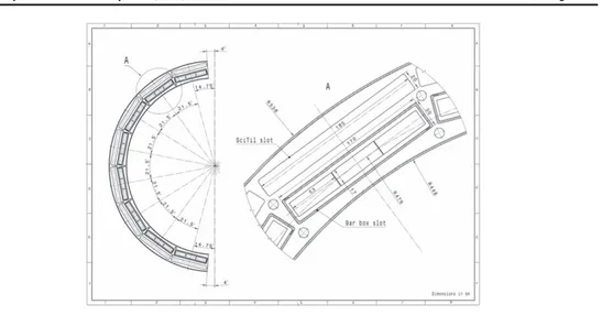
3.4.1. The PANDA Barrel DIRC baseline design. The baseline design of thePANDA Barrel DIRC detector is shown infigures9and10. 16 optically isolated sectors, each comprising a bar box and a solid fused silica prism, surround the beam line in a 16-sided polygonal barrel with a radius of 476 mm and cover the polar angle range of 22°–140°.
Each bar box contains three bars of 17 mm thickness, 53 mm width, and 2400 mm length (produced by gluing two 1200 mm long bars back-to-back using Epotek 301-2 [34]), placed side-by-side, separated by a small air gap. Aflat mirror is attached to the forward end of each bar to reflect photons towards the read-out end, where they are focused by a three-component spherical compound lens on the back of a 30 cm deep solid prism, made of synthetic fused silica, serving as EV. The location and arrival time of the photons are measured by an array of 11 lifetime-enhanced MCP-PMTs with a precision of about 2 mm and 100 ps, respectively. The MCP-PMTs are read out by an updated version of the HADES TRB[35] in combination with a front-end amplification and discrimination card mounted directly on the MCP-PMTs [36]. The sensors and readout electronics are located in the region close to the backward end-cap of the solenoid where the magnetic field strength is B≈1 T.
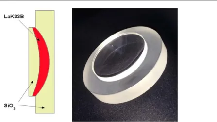
Since the image plane is located on the back surface of the prism, a complex multi-layer spherical compound lens is required to match the focal plane to this geometry using a combination of focusing and defocusing elements. A layer of lanthanum crown glass (NLaK33, refractive index n=1.786 for λ=380 nm) between two layers of synthetic fused
Figure 9.Schematic of the Barrel DIRC baseline design. Only one half of the detector is shown. Reproduced from 2017 JINST 12 C07006. © 2017 IOP Publishing Ltd and Sissa Medialab srl. All rights reserved.
silica(n=1.473 for λ=380 nm), creates two refracting surfaces. The transition from fused silica to NLaK33 is defocusing while the transition into fused silica focuses the photons. Due to the smaller refractive index differences the use of a high-refractive index material avoids the total internal reflection losses at the lens transitions that are associated with air gaps. The lens is glued to the bar with Epotek 301-2 and serves also as exit window of the bar box. The optical coupling between the bar box and the prism will be provided by a silicone cookie, made, for example, from Momentive TSE3032[37] material.
The components of the modular mechanical system are made of CFRP. The light-tight CFRP containers for the bars(bar boxes) slide into thePANDAdetector on rails that connect slots in two rings which are attached to the main support beams(see figure9). A cross section of the CFRP structure and a bar box can be seen infigure10. Similar CFRP containers house the prisms and front-end cards so that each sector is joined into one light-tight unit and optically isolated from all other sectors. To remove moisture and residue from outgassing of the bar box components as well as glue and silicone materials, the CFRP containers are constantly flushed by boil-off dry nitrogen. To facilitate access to the inner detectors of
PANDA, the modular design allows the entire frame holding the prisms, sensors, and
electronics to be detached from the barrel structure that holds the bar boxes during extended shutdowns periods. An additional advantage of the modular design is that the installation of bar boxes could be staged, in case of fabrication delays, with minimal impact on the neighboringPANDA subsystems.
A Geant simulation of the baseline design is shown infigure11. A kaon track(red line) produces Cherenkov photons(orange lines), which are detected on the MCP-PMT array. The accumulated histogram shows the distinctive hit pattern, typical for DIRC counters, where the conic section of the Cherenkov ring is projected on theflat detector plane after many internal reflections in the bar and prism.
3.4.1.1. Key design improvements. Since PANDA is smaller than the BaBar detector, several design modifications were required compared to the BaBar DIRC. Additional changes were the result of the optimization of cost versus performance. The main parameters of the DIRC counters for BaBar, BelleII, andPANDA are summarized in table 1.
Figure 10.Central cross section view of the nominal Barrel DIRC geometry, including the space for the SciTil detector.
• Radiator bar size. Due to the tight optical and mechanical specifications the fabrication of the radiator bars remains one of the dominant cost drivers for DIRC counters. A significant cost reduction is only possible if fewer pieces have to be polished. Detailed physical simulation studies(see section6and[25]) demonstrated that reducing the number of bars per bar box from 5 bars(32 mm width) to 3 bars (53 mm width) does not affect the PID performance since the lens system is able to correct for the increase in bar size.
• Compact fused silica prism as expansion volume. The overall design of the PANDA
experiment required that the large water tank used by the BaBar DIRC is replaced with a compact EV, placed inside the detector. Initial tests with a 30 cm deep tankfilled with mineral oil showed a good SPR. However, the use of mineral oil inside the detector caused concern for possible spills and the optical quality of the oil led to a loss of some 20%–30% of photons inside of the tank.
Figure 11.Geant simulation of the PANDA Barrel DIRC baseline design. The colored histogram at the bottom shows the accumulated hit pattern from 1000K+at 3.5 GeV/c and 25° polar angle, the red line shows the kaon trajectory. Reproduced from 2018 JINST 13 C03004. © 2018 IOP Publishing Ltd and Sissa Medialab srl. All rights reserved.
Fused silica as material and separated smaller units as EV were already favored by the SuperB FDIRC and the BelleII TOP. The superior optical quality increases the photon yield and the direct match of a bar box to a prism EV simplifies the alignment. The prism also allows a smaller EV opening angle compared to a larger tank since the image is folded within the EV after reflections off much higher-quality optical surfaces than a tank would provide. This reduces the photon detection area and, thus, the number of required MCP-PMTs, the other main cost driver for the Barrel DIRC. The additional reflections inside the prism are taken into account in the reconstruction software and do not cause any PID performance degradation.
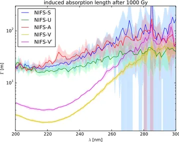
• Focusing optics. The larger bar size and the smaller EV make the use of focusing elements necessary. Initial tests, performed with a traditional spherical fused silica lens with an air gap showed sharp ring images but an almost complete loss of photon yield for track polar angles nearθ=90° due to total internal reflection at the air gap. This photon loss is avoided by using the high-refractive index material in the compound lens. Several iterations of 2-layer and 3-layer cylindrical and spherical lens designs were tested in prototypes in the optical lab and with particle beams. The latest 3-layer spherical lens achieves aflat focal surface, which is an excellent match to the prism geometry, as well as a consistently high photon yield for all polar angles. The radiation hardness of the NLaK33 material is a possible concern forPANDA and measurements of the radiation hardness in an x-ray source are currently ongoing.
• Compact multi-anode photon detectors. The smaller EV requires not only focusing optics to reduce the contribution from the bar size to the angular resolution but also smaller photodetector pixels. With a pixel size of 6.5 mm×6.5 mm MCP-PMTs meet the requirements for spatial resolution and provide a single photon timing resolution of 30–40 ps for a gain of about 106. They work in the magneticfield of 1 T and tolerate the expected photon hit rates of 200 kHz/pixel.
For many years the main challenge for the use of MCP-PMTs inPANDAwas the photon flux, expressed as the integrated anode charge. Recent improvements in the fabrication technique have increased the lifetime of MCP-PMTs to significantly more than the
Table 1.Comparison of Barrel DIRC design parameters.
BaBar BelleII TOP PANDA
Radiator geometry
Narrow bars(35 mm) Wide plates(450 mm) Wide bars(53 mm)
Barrel radius 845 mm 1150 mm 476 mm Bar length 4900 mm (4×1225 mm) 2500 mm (2×1250 mm) 2400 mm (2×1200 mm) Number of long bars
144(12×12 bars) 16(16×1 plate) 48(16×3 bars)
EV material Ultrapure water Fused silica Fused silica
EV depth 1100 mm 100 mm 300 mm
Focusing None(pinhole) Mirror Lens system
Photon detector ≈11k PMTs ≈8k MCP-PMT pixels ≈11k MCP-PMT pixels
Timing resolution
≈1.7ns ≈0.1ns ≈0.1ns
Pixel size 25 mm diameter 5.6 mm×5.6 mm 6.5 mm×6.5 mm
PID goal 3 s.d.π/K to 4 GeV/c 3 s.d.π/K to 4 GeV/c 3 s.d.π/K to 3.5 GeV/c Time line Operation 1999–2008 Installation 2016 Installation 2023
5 C cm−2integrated anode charge expected during 10 years of operating the Barrel DIRC at design luminosity.
The excellent photon timing provided by the MCP-PMTs, in combination with fast readout electronics, make it possible to measure the photon time of propagation with about 100 ps resolution. This fast timing is essential in the use of the time-based imaging, required for the wide plate design and helps in the reconstruction of the Cherenkov angle for the baseline design by suppressing ambiguities due to reflections in the bar and prism. Ultimately it may even make it possible to mitigate the influence of the chromatic dispersion of the Cherenkov angle(see equation (3.3)) and to further improve the PID performance[38].
3.4.2. The PANDA Barrel DIRC design option: wide radiator plates. A significant additional reduction of the cost of radiator fabrication would be possible if one wide plate per bar box would be used instead of 3 bars. The BelleII TOP counter demonstrated that high-quality wide plates can be fabricated by optical industry[39]. During thePANDABarrel R&D phase, two 160 mm wide prototype plates were produced by industry and found to meet the specifications.
Geant simulation and the implementation of a time-based likelihood reconstruction approach[23], inspired by the BelleII TOP, demonstrated that two designs with a wide plate, either with a cylindrical 3-layer lens or without any focusing, meet the PID requirements
forPANDA.
A Geant simulation of the design option with wide plates is shown infigure12. A pion track(red line) produces Cherenkov photons (orange lines), which are detected on the MCP-PMT array. The accumulated histogram shows the plate hit pattern which no longer exhibits the typical DIRC ring segments that were visible for the narrow bar design (figure11). The time-based reconstruction approach, however, is able to process this hit pattern to cleanly separate pions from kaons for the entire PANDA phase space.
Figure 12.Geant simulation of the PANDA Barrel DIRC design option with wide plates. The colored histogram shows the accumulated hit pattern from 1000π+ at
3.5 GeV/c momentum and 25° polar angle, the red line shows the pion trajectory.