1 INTRODUCTION
According to current seismic codes (D.M. 14/01/2008, EN 1998-1 2005), new construction de-sign is based on the capacity dede-sign, achieving a ductile structural behaviour. However, in Italy, a large number of existing r.c. buildings are designed for gravity loads only. Past earthquake effects have shown that, often, brittle mechanisms (thus more dangerous) cause severe damage or even the build-ing collapse. The beam-to-column joint failure, due to the exceeding of the joint shear strength or the bar bond slip, is comprised among these mechanisms.
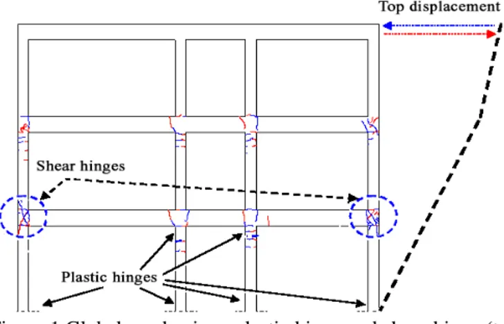
The test carried out by Calvi et al. (2001) on a r.c. frame, designed with typical details of Italian con-struction practice in the ‘60s-‘70s, showed a signifi-cant damage in the exterior joints between the first and second floor and the development of plastic hinges at the base of the columns at the ground floor. This behaviour has been also confirmed during the recent L’Aquila earthquake (2008). The develop-ment of a failure mechanism markedly different from that provided in the case of a rigid joint behav-iour, for which a soft floor mechanism would be ex-pected, was evident.
Despite the experimental evidence, typically in non-linear static and dynamic analyses, the deform-ability of the beam-column joints is commonly ne-glected: the nodal panel is assumed infinitely rigid and a verification of the strength of the joint is made
only a posteriori (Lima et al. 2010). In the last two decades different f.e. models have been proposed in order to evaluate the behavior of beam-column joints subjected to cyclic loads (Alath and Kunnath 1995; Biddah and Ghobarah 1999; Youssef and Ghobarah 2001; Pampanin et al. 2002; Lowes and Altoontash 2003; Favvata et al. 2008). Nevertheless, the com-plexity of these models has limited their application to the assessment of existing structures, without pro-viding a relatively simple tool for the study of seis-mic vulnerability of existing buildings.
Figure 1.Global mechanism: plastic hinge and shear hinge (top drift 1.6%) (Calvi et al. 2001).
This work proposes a simple f.e. model for the nodal region of external joints in concrete frames designed for gravity loads only, focusing on details of the Italian construction practice in the ‘60s-‘70s (hooked-end smooth bars, and no stirrups in the joint region).
A model for beam-column corner joints of existing r.c. frame under
cyclic loading
Paolo Riva, Consuelo Beschi
Department of Design and Technologies, University of Bergamo, viale Marconi 5, 24044 Dalmine (BG), Italy.
Giovanni Metelli, Francesco Messali
Department of Civil Engineering, Architecture, Land and Environment, University of Brescia, via Branze 43, 25123 Brescia, Italy.
ABSTRACT: Beam-to-column joints are commonly considered critic regions for r.c. frames subjected to high-magnitude earthquakes. When designed for gravity loads only, beam-to-column corner joints can not on-ly strongon-ly affect the global structural behaviour of a frame, but also be a cause of its collapse. In the paper a component-based f.e. model of external beam-to-column joints is presented. The joint deformation is mod-elled by means of two unrelated contributions, the shear deformation of the panel zone, and the rotation at the interface sections between the joint and the structural members, due to the reinforcing bars’slip within the joint core. The first part of this work focuses on the evaluation of the joint strength and stiffness. Finally, the component-based f.e. model is validated by experimental results of tests on beam-column corner joint realized according the construction practice of the 60’s-70’s, confirming the effectiveness of the presented model for the assessment of existing structures.
The proposed component based joint model al-lows to evaluate separately the shear deformation of the panel zone and the added rotation at the interface sections between the joint and the structural mem-bers converging in the joint, due to the reinforcing bars’ slip within the joint core. Furthermore, the model has been validated by the experimental results of tests carried out on full scale specimens, designed according to the Italian construction practice of the ‘60s-‘70s, with respect to both material and geomet-rical characteristics (Beschi, 2012).
2 AN ANALYTICAL MODEL FOR CORNER BEAM-COLUMN JOINTS
2.1 Joint shear strength
To evaluate the joint shear strength, for exterior r.c. beam-column joint without transverse reinforce-ment, two alternative criteria have been considered, chosen among those available in the literature be-cause of their simplicity and consistency.
The former, labelled in this work Principal Stress Limitation Model (PSLM), is based on the limitation of the tensile principal stress in the joint. The consis-tency of this model, studied specifically for joints without transverse reinforcement, with smooth hooked-ended bars, is verified in several works (Priestley 1996, Hakuto et al. 2000, Calvi et al. 2001, Masi et al. 2009).
The latter, labelled MSSTM (Modified Softened Strut-and-Tie Model), is based on the Softened Strut-and-Tie Model (SSTM) proposed by Hwang and Lee (1999) to study the behaviour of beam-column joints with transverse reinforcement. Some adjustments are herein proposed for joints designed with no transverse reinforcement and smooth bars. 2.1.1 PSLM (Principal Stress Limitation Model) For joints without transverse reinforcement, a possi-ble approach for the evaluation of the shear strength is based on the evaluation of the principal stresses in the concrete panel region (Priestley 1996; Hakuto et al. 2000; Calvi et al. 2001; Masi et al. 2009).
The principal stresses are evaluated according to the continuum mechanics equations.
The maximum tensile principal stress in the panel zone, corresponding to the development of the first diagonal crack during a first loading cycle, can be computed as follows:
p k f (1)
where fc’ is the average cylindrical compressive
strength of the concrete and k1 is a constant,
cali-brated on experimental results, with different values proposed in the literature. In this work, the value proposed for k1 is equal to 0.2, according to (Calvi et
al. 2001).
The maximum resistant shear stress, averaged in the panel zone, is defined as:
) ' /( 1 ' 1 1 c a c jh k f f k f v = + (2)
where fa is the mean compressive stress on the
col-umn section.
The joint panel maximum shear strength can be calculated as follows: j j j jh v b h V = (3)
where bj is the effective depth of the joint and hj is
the distance between the outer column reinforcing bars.
2.1.2 MSSTM (Modified Softened Strut and Tie
Model)
The proposed model is based on the Softened Strut-and-Tie Model (Hwang and Lee 1999), for which-three strut-and-tie mechanisms can be recognized in the joint region with transverse reinforcement (Fig. 2(a)). The struts consist ofun-cracked compressed concrete diagonals, whereas the ties consist ofthe stirrups and the vertical column reinforcement. In the SSTM model the ultimate joint shear strength is evaluated by using an iterative procedure where at each step the stress equilibrium, the strain compati-bility and the constitutive laws of materials are im-posed .
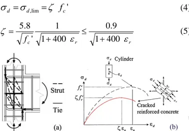
The shear strength of the joint is reached when-ever the compressive stress of the concrete diagonal strut is equal to the limit value given by the follow-ing expressions (Zhang and Hsu 1998):
' lim , c d d
σ
ζ
fσ
= = (4) r r c f ε ε ζ 400 1 9 . 0 400 1 1 ' 8 . 5 + ≤ + = (5)Figure 2. SSTM model: (a) struts and ties in the joint region; (b)softening of compressive stress-strain curve due to trans-verse tensile strain (Hwang and Lee 1999).
where σd is the average principal stress of concrete
in the d-direction; ζ is the softening coefficient (Fig. 2(b)); fc’ is the compressive strength of a standard
concrete cylinder (in units of MPa); εd and εr are the
average principal strains in the d- and r-directions (r normal to d), respectively.
The iterative procedure considers the two-dimensional compatibility condition relationships,
which relate the principal strains (εd and εr) with the
vertical and horizontal strains (εv and εh).
With respect to an exterior r.c. beam-column joint without transverse reinforcement, the only strut-and-tie working mechanism is based on a unique diago-nal concrete strut (Fig. 3).
Experimental evidence shows clearly a remark-able inclination of the strut, starting from the outside of the joint region (Fig. 3).
So, the inclination of the diagonal strut can be calculated with the following equation:
(
h /p bp)
arctan = θ (6) with: c h h hp = b + s − (7) 2 / c c p h a b = (8)where hb is the beam depth, hc is the depth of the
column section, hs is the distance between the first
stirrup outside the joint panel region for the column-joint interface section, c is the concrete cover, and
acis the depth of the compression zone in the
col-umn, defined as:
(
)
[
g c]
cc N A f h
a = 0.25+0.85 / ' (9)
where Ag is the column cross section.
The second change to the original SSTM concerns the strut depth within the panel region, which can be defined as: θ sin ' c c a a = (10)
Figure 3. Inclination of the diagonal strut: (a) experimental tests (Calvi et al. 2001); (b) SSTM (Hwang and Lee, 1999); (c) MSSTM.
2.1.3 Validations of the models
To verify the effectiveness of the two analytical criteria, PSLM and MSSTM, with the adjustments to the original SSTM, proposed by Hwang e Lee (1999), a comparison with the results of experimen-tal tests on joint specimens available in the literature is shown(Table 1).
All the specimens have smooth bars, unless the O7 specimen (Hakuto et al. 2000) characterized by
ribbed bars bent outside the joint core. However, as specified in Pampanin et al. (2003), the failure mechanism is similar to that exhibited by joints with smooth reinforcement and hooked ends.
As shown in Table 1, the PSLM, developed to study the behaviour of beam-column joints without transverse reinforcement and smooth bars, gives a reliable estimation if compared to the experimental results, while the original SSTM, developed to study the behaviour of beam-column joints with transverse reinforcement and deformed bars, widely overesti-mates the experimental values, proving to be unsuit-able to analyze joints with smooth bars and with no transverse reinfocements.
On the contrary, the proposed MSSTM, adapta-tion of the SSTM, gives a much better estimaadapta-tion of the experimental results.
Considering an average error at failure, the PSLM overestimates of about 5.6% the experimental strength, while MSSTM underestimates the experi-mental values of the same amount. It is possible to state that the adjustments made on the original SSTM allow a strut and tie method to be used also for beam-column joints without transverse rein-forcement and with smooth bars.
Table 1. Average percentage error in the evaluation of the shear strength. ERROR [%] JOINT PSLM SSTM MSSTM T1(Calvi et al 2001) +11.8 +49.3 -7.4 T23-1(Braga et al. 2001) +13.4 +27.4 -25.3 2DB(Akguzelet al., 2008) +12.7 +67.1 +4.9 2D-B(Kam et al. 2008) +3.9 +25.1 -24.6 O7(Hakuto et al., 2000) -13.6 +118 +24.6 MEAN ERROR [%] +5.6 +57.4 -5.6 2.2 Joint stiffness
The total deformation of a beam-column joint (Fig. 4(a)) is given by the sum of two contributions: the shear deformation of the panel zone (Fig. 4(b)) and the added rotation at the interface sections be-tween the joint and the structural members converg-ing in the joint, due to the slip of the reinforcconverg-ing bars within the joint core (Fig. 4(c)). It is assumed that this two phenomena are unrelated, so it is possible to deal with them separately.
Figure 4. (a) Total joint deformation; (b) Shear deformation of the panel zone; (c) rotations at the interfaces due to bond slip.
2.2.1 Joint panel shear deformation
The total rotation of the joint panel due to the shear acting in the joint is given by two contribu-tions, as shown in Figure 5:
V H jh γ γ
γ = + (11)
with γH and γV the horizontal and vertical rotations of
the joint panel sides, respectively.
Figure 5. Shear panel deformation: (a) PSLM; (b) MSSTM.
The value of γjh depends on the method adopted
for the joint shear strength calculation.By using the PSLM, the shear panel deformation can be calcu-lated according to continuum mechanics as ex-pressed by the following equation:
(
)
jh jh jh v E v G ν γ = 1 = 21+ (12)where vjh is the shear strength of the joint, calculated
with Equation 2.
By using the MSSTM, the evaluation of the shear panel deformation is related to the ultimate strength of the compressed concrete, since the joint shear strength depends on the diagonal strut compressive strength.
At collapse, the concrete compressive strain can be defined as:
0
ζε
εd = (13)
where ε0 is the strain corresponding to the peak
compressive strength fc’ and ζ is the softening
coef-ficient, calculated with Equation 5, used to consider the strength reduction due to the biaxial stress state in cracked concrete (Fig. 2(b)).
If ignoring the expansion of the joint panel nor-mally to the diagonal strut due to concrete diagonal cracking, simple trigonometric expressions give the rotation γjh:
(
θ θ)
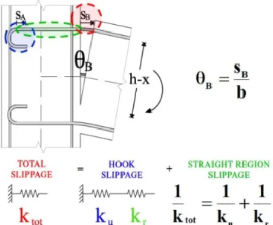
ε ζ γ γ γ tan 1/tan 2 1 0 + = + = H V jh (14)2.2.2 Joint panel deformation due to bond-slip For the evaluation of the added rotations at the inter-faces between the joint and the structural members, a slip estimation of the bar straight lengthand of the hooked-end is needed. Both the contributions are
modelled as two springs in series, whose stiffness determines the rotation θB (Fig. 6).
Figure 6. Contributions of bar slip to member-joint interface section rotation.
To determine the relation between the stress and the slip in the hook, the experimental curves illus-trated in Fabbrocino et al. (2002) are bi-linearized using the OLS (Ordinary Least Squares) method (Fig. 7).
Figure 7. Stress-slip experimental curves for hooked-end bars (Fabbrocino et al., 2002).
The bond stress along the bar within the joint is supposed to be uniform whether the reinforcement remains elastic (τE =0.3 fck0.5 – hot rolled bars, good
bond conditions) or it is loaded beyond yield (τy
=ΩτE), according to the NMC2010 draft (fib, 2010);
consequently, the bar stress varies linearly. For rein-forcing steel, a stress-strain relationship with harden-ing is adopted, with a post-elastic tangent stiffness
Eh equal to the 0.5% of the elastic modulus Es.
To evaluate the slip reinforcement along the straight region, the local equilibrium and compatibil-ity equations are integrated along the bond length. The boundary conditions depend on whether the re-inforcement remains elastic or it is loaded beyond yield, either the hook is loaded or it is not (Fig. 10). The integration allows to calculate the total slip at the interface section between the joint and the linked members.
This method can be applied to deformed bars too. Further details can be found in the report (Beschi et al. 2011). As example, Figure 8 shows the bar slip values (normalized with respect to the bar diameter) as the tensile bar stress (normalized with respect to the yielding stress) varies, and for different steel ty-pologies.
Figure 8. Normalized bar slip, with respect to the bar diameter for different steel strength.
3 COMPONENT-BASED JOINT MODEL
Over the last four decades, several approaches have been proposed for modelling the seismic response of r.c. beam–column joints, given the recognized im-portance of joint non-linearity on the overall struc-ture behaviour. These models are called “compo-nent-based models”, because they don’t represent the joint region as a continuum, but they are made ofone or more elements representing each mecha-nism which contributes to the joint global behaviour.
In the present research work an f.e. explicit model has been developed, being each non-linear mecha-nism governing the joint behaviour taken into ac-count, such as bar slip through the joint and shear failure in the joint core. The f.e. model has been ap-plied to an exterior beam-column joint of a frame sub-structure. This sub-structure is made of the parts of the beam and the column converging in the joint, being included among the inflection points of the structural elements belonging to a frame subjected to horizontal actions and conventionally placed at midspan of the beam and mid-height of the column.
Figure 3.Joint f.e. model.
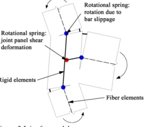
As shown in Figure 9, in the f.e. model, devel-oped with the software MIDAS/Gen (2010), the beam and the column are modelled with fiber ele-ments, with diffuse plasticity: the Kent & Park and the Menegotto-Pinto models have been used for the constitutive law of concrete and steel bar, respec-tively; the portions of the beam and the column
within the joint region are modelled with rigid ele-ments; to model the shear deformation of the joint panel region, a rotational spring is adopted, and also the deformations due to bond-slip are model with ro-tational springs: two springs for the column rein-forcement slip and one spring for the beam bars’ slip, placed at the interface between the joint and the elements converging in it.
The cyclic shear behaviour of the panel zone is modelled by a moment Mjh – shear deformation γih
spring adopting a hysteretic Takeda model, with a bilinear and non degrading skeleton curve to take into account the energy dissipation within the joint. The definition of the Mjh – γih curve requires the
evaluation of the bending moment Mjh acting in the
beam at the column-beam intersection node and cor-responding to the joint shear strength Vij which
gen-erates a shear deformation γih. The Mjh value is
ob-tained by:
(
b bn)
byjh L L M
M = / λ , (15)
where Lb and Lbn are the span between two adjacent
column axes, and the relative free span of the beam,
Mb,y the beam moment resistance at the bar yielding,
and λ is the fraction between the joint shear strength (Vjh) and the shear value which generates on the
beam the bending moment Mb,y, as defined by the
following equation: c y b bn b y s y jh L M L L f A V , , = − ⋅ (16)
where As is the longitudinal reinforcement cross
sec-tion, and fyis the bar yield strength.
Equations 15 and 16can be easily determined by applying the equilibrium equations on the modeled sub-structure (Fig. 10).
Figure 4.Forces on the modeled sub-structure.
Three rotational springs have been adopted to model the effects of the bar slip in the joint: two for column bars’ slip and one for beam bars’ slip, placed at the interfaces between the structural members and the joint. The model used to describe bond slip be-haviour is a slip bilinear type hysteresis model, as
zb C T = As fs bb L Lbn Lb Mb Vb Vjh Vjh VC VC
shown in Figure 12 Thus, the first yielding moment of the section of the beam at joint interface (Mb,y),
the rotation due to bond-slip of beam reinforcement when the stress in the bars is equal to the yield strength(θB,y), the spring elastic stiffness (kE) and the
stiffness after bar yielding (ky) must be evaluated.
Figure 5.Takeda bilinear type hysteresis model.
Figure 6.Slip bilinear type hysteresis model.
The rotation at beam-joint interface is supposed to be equal to the slip sB of the rebars divided by the
internal lever arm b taken equal to the difference be-tween the beam depth (d) and the position of the neutral axis (x), conventionally considered equal to
h/3 as shown in Figure 6.
4 VALIDATION OF THE F.E. MODEL
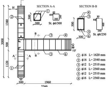
In this section the proposed model is applied to ana-lyze the exterior beam-column joint, specimen T1, tested in (Calvi et al 2001) as a part of a research on the seismic behaviour of RC beam-column joints de-signed for gravity loads, with the typical structural deficiencies of constructions built before the ‘70s (Fig. 13).
Figure 7.Geometrical characteristics and reinforcement details of specimen T1 (Calvi et al. 2001).
The mean concrete compressive strength was equal to 23.9 MPa, whereas the yielding and ulti-mate steel strength varied between 345 and 385 MPa, and between 403 and 458 MPa respectively, depending on the bar diameter.
Both the two criteria (PSLM and MSSTM) give a good evaluation of the joint strength, with differ-ences in the order of 7.3% for PSLM and 11% for MSSTM, remembering that the PSLM has been de-veloped properly for exterior beam-column joint with substandard details and calibrate on the base of the experimental results, while MSSTM is an adap-tation of a model born for confined joints. Further-more Figure 14 shows the importance of the bond-slip effects in the model to tune the numerical results to the experimental ones in term of joint stiffness and hysteretic behaviour (Tab. 2).
(a)
(b)
Figure 8.Comparison between experimental and numerical re-sults on specimen T1: (a) PSLM; (b) MSSTM.
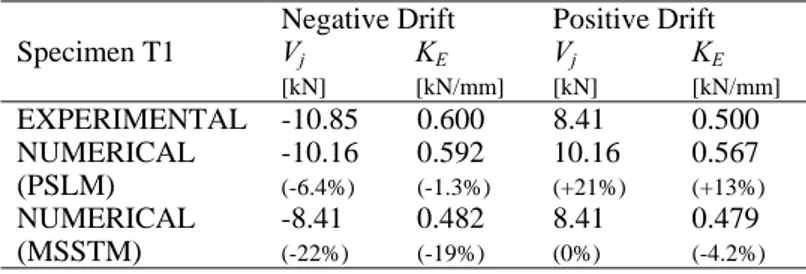
Table 2. Comparison between experimental and numerical re-sults on specimen T1.
Specimen T1
Negative Drift Positive Drift Vj [kN] KE [kN/mm] Vj [kN] KE [kN/mm] EXPERIMENTAL -10.85 0.600 8.41 0.500 NUMERICAL (PSLM) -10.16 (-6.4%) 0.592 (-1.3%) 10.16 (+21%) 0.567 (+13%) NUMERICAL (MSSTM) -8.41 (-22%) 0.482 (-19%) 8.41 (0%) 0.479 (-4.2%)
Vjis the horizontal shear value which causes the joint failure.
The proposed model has been also validated by further experiment tests on full scale corner joint of the first floor of a realistic building, designed ac-cording to the Italian construction practice of the ‘60s-‘70s, with respect to both material and
geo-metrical characteristics. The tests were carried at the University of Bergamo. A joint design was per-formed according to the codes provisions in force at the time of construction and the construction prac-tice (D.M., 1974; Santarella, 1947). The specimens (labelled CJ1 and CJ2) have been designed only for gravity loads: the columns carry a centred normal action and the beams are designed according to the scheme of continuous beam on multiple supports, with upper reinforcements at the beam ends to con-trol the crack width for service load. The column cross section is 30x30 cm, with 4 Ø16 mm longitu-dinal rebars and with Ø6@150 mm stirrups. The main spandrel beam is characterized by a 30x50 cm cross section,with smooth reinforcing bars with hooked-end anchorages. According to ‘60s-‘70s no transverse reinforcement were placed inside the joint (Fig. 15).Smooth steel bars, with mechanical proper-ties similar to those typically used in the ‘60s-‘70s, have been adopted for both longitudinal and trans-verse reinforcement. The yield strength fym of
longi-tudinal reinforcement was equal to 365 MPa or to 445 MPa for Ø12 mm and Ø16 mm diameter bar while it. The compressive concrete strength fym was
equal to 38 MPa.
During the test, at first the column was axially loaded and a pre-load was applied to the beam simu-lating the gravity loads, afterwards a cyclic gradual-ly increasing lateral displacement was applied to the column top.All the details of the test set up, test re-sults and the calculation of all the parameters which allow to define the strength and stiffness of the springs adopted in fem can be found in (Beschi, 2012). The present paper focuses only on the valida-tion of the proposed component-based f.e. model.
In Table 3 the comparison between the experi-mental and numerical results is shown: for the nega-tive direction the specimen collapse is due to the joint shear failure while in the positive direction the failure is governed by the plastic hinge in the beam, as expected by the two analytical models.
As the two specimens showed a similar trend, the results in terms of horizontal load versus displace-ment curve are plotted for the specimen CJ1 only and compared to the numerical simulation (Fig.15). For negative drift both the methods are in very good agreement with the experimental values: considering the peak load value at a drift equal to -1%, the PSLM under-estimates the experimental value of about 3.8% and 2.3% for specimen CJ1 and CJ2 re-spectively, while the MSSTM under-estimates it of about 1.6%.
In the positive direction both methods under-estimate the experimental results with a maximum error of 13.8% (specimen CJ2).
In the numerical analyses the pinching of the hys-teresis loops due to the slip of the reinforcing bars is captured, although for drift following the peak re-sistance, the shape of the cycles is not representative
of the real behavior, as the model does not take into account the strength degradation connected to the damage in the joint panel region.
Figure 9.Geometrical characteristics and reinforcement details of tested specimen.
Table 3.Comparison of experimental and numerical results
TEST RESULTS Error of the numerical evaluation [%] PSLM MSSTM Load direction + - + - + - Fmax [kN] CJ1 29.5 -36.0 -6.6 -3.8 -6.6 -1.6 CJ2 32.0 -35.4 -13.8 -2.3 -13.8 0.0 Kt [kN/mm] CJ1 1.19 -1.03 +4. 6 -6.1 -9.9 +3. 8 CJ2 1.19 -1.09 +4. 2 +1. 0 -10.3 -1.4
Figure 10.Comparison between numerical and experimental re-sults for the CJ1 specimen.
5 CONCLUSIONS
Nowadays, in RC frames designed before the ’70s it is widely recognized that beam-column joints
repre-‐40 ‐35 ‐30 ‐25 ‐20 ‐15 ‐10 ‐5 0 5 10 15 20 25 30 35 ‐3.5 ‐3.0 ‐2.5 ‐2.0 ‐1.5 ‐1.0 ‐0.5 0.0 0.5 1.0 1.5 2.0 2.5 3.0 3.5 Horizontal displacement [mm] Ho riz o nt al lo ad [k N ] ‐105 ‐90 ‐75 ‐60 ‐45 ‐30 ‐15 0 15 30 45 60 75 90 105 Drift [%] Experimental results CJ1 MSSTM f.e.m. results
sents critical regionsunder seismic loads (in particu-lar corner beam-column joints), influencing the re-sponse of the whole structural system, as demon-strated during recent earthquakes.
In the paper a component-based f.e. model to es-timate the structural behaviour of a corner beam-to-column joint of a frame designed for gravity loads only, according to ‘60s-‘70s design practice, is pre-sented.
The joint deformation is modelled by means of two unrelated contributions, which are the shear de-formation of the panel zone, and the added rotation at the interface sections between the joint and the structural members, due to the reinforcing bars’slip within the joint core.Two analytical method are pro-posed to calculate the joint shear strength (PSLM and MSSTM), based on the calculation of tensile principal stress in the panel joint and of the com-pressive strength of the strut within the joint, respec-tively.
Finally, the component-based f.e. model is vali-dated by experimental results of tests on beam-column corner joint realized according the construc-tion practice of the 60’s-70’s, thus confirming the ef-fectiveness of the presented model for the assess-ment of existing structures by the modelling of bar slip within the joint.
REFERENCE
Akguzel, U., Pampanin, S., 2008. Effects of variation of axial load and bi-directional loading on the FRP retrofit of exist-ing B-C-Joints, The 14th World Conference on Earthquake Engineering. Beijing, Cina.
Alath, S., Junnath, S. K., 1995. Modelling Inelastic Shear De-formation in RC Beam-Column Joints. Engineering Me-chanics: Proceedings of Tenth Conference, (pp. 822-825). University of Colorado.
Beschi, C., Messali, F., Metelli, G., Riva, P. 2011. Analisi di nodi trave-pilastro in calcestruzzo armato soggetti ad cicli-che. Technical Report n. 3, University of Brescia.
Beschi, C., 2012. Retrofitting of beam-column joints under sesimic loads, Ph.d Thesis, University of Brescia.
Biddah, A., & Ghobarah, A., 1999. Modelling of Shear Defor-mation and Bond Slip in Reinforced Concrete Joints. Struc-tural Engineering and Mechanics, 7 (4), 413-432.
Calvi, G. M., Magenes, G., Pampanin, S., 2001. Studio speri-mentale sulla risposta sismica di edifici a telaio in cemento armato per soli carichi da gravità. X Congresso Nazionale "L'Ingegneria Sismica in Italia". Potenza-Matera.
Decreto ministeriale 14 gennaio 2008, Norme tecniche per le costruzioni, G.U. n. 29 del 4 febbraio 2008
Decreto Ministeriale 30/05/1974, Norme tecniche per la esecu-zione delle opere in cemento armato normale e precompres-so e per strutture metalliche.
EN 1998-1 2005, Eurocode 8 Progettazione delle strutture per la resistenza sismica – Parte 1: Regole generali, azioni si-smiche e regole per edifici.
Fabbrocino, G., Verderame, G. M., Manfredi, G., Cosenza, E., 2002. Experimental response and behavioral modelling of anchored smooth bars in existing RC frames. Bond in Con-crete - from research to standars. Budapest.
Favvata, M. J., Izzudin, B., Karayannis, C. G., 2008. Modelling exterior beam-column jointsfor seismic analysis of RC frame structures. Earthquake Engineering and Structural Dynamics , 37, 1527-1548.
fib Bulletin 55, Model Code 2010 – First complete draft, Vol-ume 1 (chapters 1-6), 318 pages, ISBN 978-2-88394-95-6. Hwang, S. J., Lee, H. J., 1999. Analytical model for predicting
shear strengths of exterior reinforced concrete beam-column joints for seismic resistance, ACI Structural Journal , 96 (5), 846-858.
Hakuto, S., Park, R., & Tanaka, H., 2000. Seismic load tests on interior and exterior beam-column joints with substandard reinforcing details, ACI Structural Journal , 97 (1), 11-25. Kam, W. Y., Quintana Gallo, P., Akguzel, U., Pampanin, S.,
2008. Influence of Slab on the Seismic Response of sub-standard Detailed Exterior Reinforced Concrete Beam-Column Joints. Retrofit Solutions for NZ.
Lima, C., Martinelli, E., Macorini, L., Izzudin, A., 2010. Com-portamento non lineare di nodi esterni trave-colonna in c.a.: modelli locali di capacità ed influenza sulla risposta sismica globale. 18° Congresso C.T.E. (pp. 693-702). Brescia: Edi-zioni Imready.
Lowes, L. N., Altoontash, A., 2003. Modeling reinforced-concrete beam-column joints subjected to cyclic loading. Journal of Structural Engineering , 129 (12), 1686-1697. Masi, A. (2004). Valutazione della Resistenza Sismica di
Strut-ture Intelaiate in C.A. Progettate negli Anni '70.
Masi, A., Santarsiero, G., Verderame, G., Russo, G., Martinel-li, E., Pauletta, M., et al., 2009. Capacity models of beam-column joints: provisions of european and italian seismic codes and possible improvements. Eurocode 8: Perspective from the Italian standpoint Workshop (pp. 145-158). Napo-li: Doppiavoce.
Midas Gen. Gen 2010 On-line Manual. Midas Information Technology Co., Ldt. http://www.MidasUser.com.
Pampanin, S., Magenes, G., Carr, A., 2003. Modelling of shear hinge mechanism in poorly detailed RC beam-column joints. Procedings of the FIB 2003 Symposium May 6-8 2003, (pp. CD-ROM). Atene, Grecia.
Priestley, M. J., 1996. Displacement-based seismic assesment of reinforced concrete buildings. Journal of EarthquakeEn-gineering , 1 (1), 157-192.
Santarella, 1947Il Cemento Armato - Volume II - Le applica-zioni alle costruapplica-zioni civili ed industriali. Milano: Hoepli. Youssef, M., Ghobarah, A., 2001. Modelling of RC
Beam-Column Joints and Structural Walls. Journal of Earthquake Engineering , 5 (1), 93-111.
Zhang, L. X., & Hsu, T. T., 1998. Behavior and analysis of 100 MPa concrete membrane elements. Journal of Structural Engineering , 124 (1), 24-34.
ACKNOLEDGMENTS
The Authors are grateful to Master student Luca Bordoni for his assistance in carrying out the tests.
Daniele Di Marco of the Laboratory Test and Ma-terials of the University of Bergamo is also grate-fully acknowledged for his know-how and expertise in assembling the test specimens.
The support of Schnell spa, who provided the steel bars and manufactured the specimens, is grate-fully acknowledged as well as Calcestruzzi spa, who provided the concrete of the tested specimen.
![Table 1. Average percentage error in the evaluation of the shear strength. ERROR [%] JOINT PSLM SSTM MSSTM T1 (Calvi et al 2001) +11.8 +49.3 -7.4 T23-1 (Braga et al](https://thumb-eu.123doks.com/thumbv2/123dokorg/5520491.64321/3.892.56.412.669.940/table-average-percentage-evaluation-strength-error-calvi-braga.webp)