To you our gratitude for ever.
This book is dedicated to the memory of Piero Lunghi, creator of the European Fuel Cell Technology
and Applications Conference, dear friend and colleague, who prematurely passed away in a car
accident on damned November 9, 2007.
Piero made significant contributions in the field of fuel cells in the course of his too short career. He
was the leading figure in the formation of the fuel cell research group at the University of Perugia
and several activities and research projects initiated by him are still ongoing. This means that, thanks
to Piero, many young people are working in this exciting research field and are coming to Naples to
present their results. Therefore, Piero’s memory is in the conference name but Piero’s contribution
is still in the contents of this book.
The memory of our friend Piero, his great personal generosity and energy, survives in our hearts, his
contribution and his tenacity survive in the work of young people who carry on his vision throughout
the world.
This year three best paper awards have been established in memory of Piero Lunghi, following his
ideas and his actions “Plan as if you should live forever and work as if you should die tomorrow”.
The prize that has been made possible by his parents and his sister, Paola, aims to be a message to
young researchers everywhere: your ideas, your projects can change the world.
Give them your passion, your strength, and make all necessary effort to realize them. There is no
greater satisfaction than seeing one’s ideas become reality and become part of the future of our
EdiTEd by Viviana Cigolotti
Co-EdiTEd by
Chiara Barchiesi and Michela Chianella 2017
ENEA
ITALIAN NATIONAL AGENCY FOR NEW TECHNOLOGIES, ENERGY AND SUSTAINABLE ECONOMIC DEVELOPMENT
Lungotevere Thaon di Revel, 76 00196 ROME
LOCAL COMMITTEE
CHAIRMANAngelo MORENO
ENEA (Italian National Agency for New Technologies, Energy and Sustainable Economic Development) - Italy TECHNICAL PROGRAM MANAGER AND AUTHOR INFORMATION
Viviana CIGOLOTTI
ENEA (Italian National Agency for New Technologies, Energy and Sustainable Economic Development) - Italy
Stephen McPHAIL
ENEA (Italian National Agency for New Technologies, Energy and Sustainable Economic Development) - Italy
Elio JANNELLI
Dept. of Engineering - University of Naples “Parthenope” - ATENA Scarl Italy
Adele PIANESE
Dept. of Engineering - University of Naples “Parthenope” - ATENA Scarl Italy
Ludovica COSENTINO
ATENA Scarl, Italy
oRgANiziNg COMMITTEE
CHINA
Hongmei Yu, dalian institute of Chemical Physics
FiNLANd
Jari Kiviaho, VTT Technical Research Center of Finland
FRANCE
Laurent Antoni, CEA and President of the New European Research Grouping on fuel cells and Hydrogend
GERMANY
Detlef Stolten, Forschungszentrum Jülich (FZJ)
Christian Sattler, DLR - German Aerospace Center, Vice-President of N.ERGHY
Olaf Jedicke, Karlsruhe Institut of Technology (KIT)
iTALy
Alberto Ravagni, SOFCPower Spa
Gianni Bidini, Università degli Studi di Perugia
Stefano Ubertini, Università degli Studi della Tuscia
Marcello Baricco, Università degli Studi di Torino
Luigi Crema, Fondazione bruno Kessler
Salvatore Freni, director of CNR iTAE
JAPAN
Takao Watanabe, Central Research institute of Electric Power Industry (CRIEPI)
NETHERLANDS
Marc Steen, Head of Unit Cleaner Energy, Institute for Energy, Joint Research Centre, European Commission
ROMANIA
Eden Mamut, University of Costanza
SPAIN
Fernando Palacin, Director at the Foundation for Hydrogen in Aragon
Iñaki Azkarate, Tecnalia Corporación Tecnológica
SOUTH KOREA
Tae-Hoon Lim, Korea Institute of Science & Technology (KIST)
SWEDEN
Bengt Ridell, Sweco Energuide AB
USA
Subhash Singhal, Pacific Northwest National Laboratory (PNNL)
SCIENTIFIC COMMITTEE
TRACK MANAGER
BULGARIA
Daria Vladikova, IEES
CRoATiA
Frano Barbir, FESB - University of Split
DENMARK
John Bögild Hansen, Haldor Topsøe
FiNLANd
Tiina Koljonen, Technical Research Center of Finland (VTT)
FRANCE
Michel Cassir, Chimie Paris Tech (ENSCP)
Deborah Jones, Université Montpellier
GERMANY
Alexander Michaelis, Fraunhofer-institut für Keramische Technologien und Systeme - IKTS Dresden
Thomas Pfeifer, Fraunhofer-institut für Keramische Technologien und Systeme - IKTS Dresden
Ludwig Jörissen, Centrum für Sonnenenergie- und
Wasserstoff-Forschung Baden-Württemberg - ZSW
gREECE
Tsiakaras Panagiotis, University of Thessaly
Thanos Stubos, National Center for Scientific Research «demokritos»
iTALy
Mauro Scagliotti, R.S.E. Spa - Ricerca sul Sistema Energetico
Aristide Massardo, Università degli Studi di Genova
Maria Giovanna Minutillo, Università degli Studi di Napoli “Parthenope”
Alessandra Perna, Università degli Studi di Cassino
Umberto Desideri, Università degli Studi di Pisa Angelo Basile, ITM-CNR – Istituto per la Tecnologia delle Membrane del Consiglio Nazionale delle Ricerche
Sergio Ulgiati, Università degli Studi di Napoli “Parthenope”
Vincenzo Palma, Università degli Studi di Salerno
Cesare Pianese, Università degli Studi di Salerno
Barbara Bosio, Università degli Studi di Genova
Rodolfo Taccani, Università degli Studi di Trieste Pierluigi Leone, Politecnico di Torino
Nicola Massarotti, Università degli Studi di Napoli “Parthenope”
Luca Andreassi, Università degli Studi di Roma “Tor Vergata
Andrea Casalegno, Politecnico di Milano
Massimo Santarelli, Politecnico di Torino
Vito Di Noto, Università degli Studi di Padova
Domenico Borello, Università di Roma “La Sapienza”
Pierangela Cristiani, RSE - Ricerca sul Sistema Energetico S.P.A.
Linda Barelli, Università degli Studi di Perugia
Marcello Romagnoli, Università degli Studi di Modena e Reggio Emilia
Antonino Aricò, CNR iTAE
Gaetano Squarito, CNR iTAE
Stefano Campanari, Politecnico di Milano
JAPAN
Koichi Eguchi, Kyoto University
NETHERLANDS
Kas Hemmes, Delft University of Technology - TU Delft
P.V. Aravind, Delft University of Technology - TU Delft
PORTUGAL
Carmen Rangel, LNEg - National Laboratory of Energy and geology
ROMANIA
Vasile Stanciu, The National R-d institute for Cryogenics and isotopes Technologies - iCiT
Iordache Ioan, Institutul Naţional de Cercetare-Dezvoltare pentru Tehnologii Criogenice şi Izotopice – ICSI Rm. Vâlcea
SLOVENIA
Stanko Hocevar, National Institute of Chemistry of Slovenia
SOUTH KOREA
Suk Woo Nam, Korea Institute of Science & Technology (KIST)
Jonghee Han, Korea Institute of Science & Technology (KIST)
Sung Pil Yoon, Korea Institute of Science & Technology (KIST)
Jaeyoung Lee, GIST
SPAIN
Javier Brey Sanchez, H2B2
Garcìa Luis Alberto, Tecnalia Corporación Tecnológica
David Sanchez, University of Sevilla
Antonio García-Conde, Spanish Hydrogen Association - IEA HIA
SWEDEN
Bin Zhu, Royal institute of Technology
Carina Lagergren, KTH
SWITZERLAND
Olivier Bucheli, Solid Power
TURKEY
Cigdem Karadag, TUBITAK Marmara Research Center
Atilla Ersoz, TUBITAK Marmara Research Center
Isil Isik Gulsac, TUBITAK Marmara Research Center
Fehmi Akgun, TUBITAK Marmara Research Center
UK
Vladimir Molkow, University of Ulster
Robert Steinberger-Wilckens, University of Birmingham
Ioannis A. Ieropoulos, University of the West of England, Bristol
USA
Abdelkader Hilmi, Fuel Cell Energy
Whitney Colella, gaia Energy Research institute
J. Robert Selman, illinois institute of Technology
Martin Andersson Steven Beale Manuel Bianco Remi Costa Pierangela Cristiani Nicola Di Giulio Ioannis Ieropoulos Carina Lagergren Pierluigi Leone Stephen McPhail Mariagiovanna Minutillo Alessandra Perna Rodolfo Taccani Francesco Trasino Alberto Traverso
ExHIBITOR
SPONSOR
Located in the Science Park of the Swiss federal institute of technology (EPFL) in Lausanne, Fiaxell is manufacturing components for SOFC and SOEC research such as the Open Flanges test Set-Up™, short stack, gold, crofer 22H and nickel M_Grid™, Cell-Connex™ for current collection and gas diffusion. We are also retailer for H2 generator, potentiostat/galvanostat/EIS analyzer and mass flow controller.
The Institute for Advanced Energy Technologies “Nicola Giordano” (hereinafter ITAE) is an italian research centre founded in 1980 and belonging to the National Research Council (CNR) that is distributed all over Italy through a network of institutes aiming at promoting a wide diffusion of its competences throughout the national territory and at facilitating contacts and cooperation with local firms and organizations.
iTAE is one of European leading research centre in the fuel cells and renewable energy fields and a full member of the Fuel Cells and Hydrogen Joint Technology initiative of the European Community.
The research activity is organized in 4 sectors: 1 – Direct production of electric energy technologies 2 – Hydrogen and clean fuels production
3 – Energy transformation and storage technologies 4 – Integration of new energy technologies and renewable
beside these four lines of research, there are three support activities that cut across all research lines and are: socio-economic impact analysis of cutting-edge energy technologies; study about the regulations governing the application and use of energy technologies; technology transfer and exploitation of R&D results.
The institute is provided with 19 equipped laboratories for preparative and characterization of materials and components, energy systems and for the construction and testing of devices and prototypes.
These laboratories are located in a building which is on three levels with a total area of 4800 square meters, and includes laboratories, offices, a conference room, a library, a guest quarters and the canteen.
The Bioelectrochemical Society (BES) is an international scientific association founded by Giulio Milazzo in 1979 to promote understanding and cooperation among scientists interested in the application of electrochemical concepts and techniques to the fundamental or applied study of living systems.
BES is a non-profit making organization. The Society is composed of individuals and corporate members in the following categories: regular, honorary.
BES pursues its objective using various means, including: • organising scientific meetings;
• publishing scientific works in periodicals or other forms; • editing specialized periodicals;
• contributing to the development of a common language among scientists of the different disciplines involved in the (scientific, technical and applied) development of bioelectrochemistry, especially among the diverse groups interested in such aspects as energetics, pharmacology, medicine, etc.;
• stimulating the establishment, among its members, of co-operative programs on particular subjects, especially interdisciplinary, and, if the need arises, assuring the management of international programmes of study or research. • attributing awards in the field of the Bioelectrochemistry. BES is administered by a Council elected during BES biannual
The FCH JU programme is structured around
two research and innovation pillars dedicated
to Transportation and Energy Systems,
complemented by a set of Cross-Cutting
research activities.
ENERGY
TRANSPORT
CROSS-CUTTING ISSUES
(e.g. standards, consumer awareness,manufacturing methods, studies)
Road vehicles
Non-road mobile vehicles and machinery Refuelling infrastructure
Fuel cells for power and combined heat & power generation
Hydrogen production and distribution Hydrogen for renewable energy storage
(incl. blending in natural gas grid)
The Fuel Cells and Hydrogen Joint Undertaking (FCH JU) finances Research & Development (R&D) and Demonstration projects
on fuel cells and hydrogen. It is a unique public-private partnership between the European Commission, Europe’s fuel cell
and hydrogen industry and research organisations. A public-private partnership model works as an effective way for European
intervention to coordinate R&D activities by pooling financial resources together.
The European Union is committed to changing its transport and energy systems in pursuing a future low carbon economy.
Fuel Cells and Hydrogen (FCH) technologies hold great promise for energy and transport applications from the perspective of
meeting Europe’s energy, environmental and economic challenges.
Hydrogen can be produced using renewable energy sources, offering a clean fuel for road transportation. Moreover, hydrogen
offers the ability to store electricity, addressing the intermittent character of renewable energy. When coupled with highly
efficient, silent and clean fuel cells as energy convertors, hydrogen opens up new horizons for decreasing Europe’s dependency
on imported fossil fuels.
The aim of the FCH JU is to accelerate the market introduction of these technologies, realising their potential as
an instrument in achieving a carbon-lean energy system.
Established in 2008, the FCH JU has supported 169 projects to date. Its second phase was approved by the Council of the
European Union in May 2014 under the Horizon 2020 EU funding programme, with a total budget of €1.33 billion as FCH 2 JU.
This marks Europe’s continued confidence and support for fuel cells and hydrogen as key technologies for decarbonising our
energy system, and creating a secure sustainable energy supply capable of generating new jobs.
EFC17 EUROPEAN
HYDROGEN TOUR
from Brussels to Naples
The EFC17 European Hydrogen tour has two main goals.
We intend to let European citizens, but above all italian citizens, know that the electric Hydrogen and fuel cell vehicles are ready to enter the market. These vehicles together with battery electric ones and with all other electric vehicles based on the combination of battery and hydrogen fed fuel cells are the future of zero emissions transport. They are the answer to pollution problems and to improve the quality of our life. Another goal, which is more peculiar for italy, is to highlight how late italy is in the deployment of hydrogen infrastructures and in the promotion, in general, of the research and development
of hydrogen and fuel cells technologies . We would like to make italian politician aware of the importance of these technologies for our economy, for creation of new employments, for enhancing our competitiveness . During the first part of the trip two hydrogen cars , supplied by FCH-JU, a Hyundai Ix35 and a Toyota Mirai, will cross Belgium, Germany and Austria to reach Bolzano (Italy). In this case we won’t have any problem because we will be able to fill the cars with Hydrogen in public HRS we will find along the trip just using the application H2.Live in our Smartphone. We are going to face many problems in the second part of the tour, i.e. from Bolzano to Naples. There are no public HRS we will be obliged to refill hydrogen in facilities where Hydrogen is produce and/or stored.
Brussels Stuttgart Bozen Florence Rome Naples
MEDIA PARTNERS
Fuel Cell & Hydrogen Energy Association (FCHEA) is the trade association for the fuel cell and hydrogen energy industry, dedicated to the commercialization of fuel cells and hydrogen energy
technologies. FCHEA members represent the full global supply chain, including fuel cell materials, components and systems manufacturers, hydrogen producers and fuel distributors, government laboratories and agencies, trade associations, utilities, and other end users.
Fuel Cells Bullettin is the leading monthly newsletter dedicated to reporting and analysing business and technology developments in the global fuel cell sector. The newsletter – published as a Digital Edition - contains a mix of news on automotive and mobile, small and large stationary, portable and micro, hydrogen fuelling and energy storage, commercialisation and research activities and demonstrations. Each issue has a feature article on a specific company, project, technology or topic of interest, as well as an extensive summary of new US patents, and a comprehensive events calendar.
Renewable Energy Focus magazine and its website provide a forum for debate and dialogue between research, industry, financial organisations and government bodies worldwide. With in-depth coverage and incisive editorial on all areas of renewable energy, Renewable Energy Focus takes an objective look at bioenergy, energy efficiency, energy infrastructure, energy storage (including fuel cells), geothermal, green buildings, hydro power, photovoltaic (PV), solar heating and cooling, solar thermal, wave and tidal energy, and wind power.
Shmuel De-Leon Energy, Ltd. is a leading company in the field of power sources knowledge. The company provides comprehensive collection of power sources knowledge tools and services: • Consulting services
• Market research reports
• Batteries , Fuel cells and EV seminars and conferences • Batteries, FC & EV Weekly newsletter
• Energy Sources On-Line web DataBase (batteries, fuel cells, capacitors and more...)
• Power sources solutions
• Representing Energy Storage testing and research equipment companies in israel
MEDIA PARTNERS
The mission of The Electrochemical Society is to advance theory and practice at the forefront of electrochemical and solid state science and technology, and allied subjects.To encourage research, discussion, critical assessment, and dissemination of knowledge in these fields, the Society holds meetings, publishes scientific papers, fosters training and education of scientists and engineers, and cooperates with other organizations to promote science and technology in the public interest.The vision of ECS is to be recognized as the steward of electrochemical & solid state science and technology. By creating uninhibited availability of the science through open access, ECS can Free the Science, and accelerate scientific discovery and innovation, leading the community as the advocate, guardian, and facilitator of our technical domain.
American Elements is the world leader in the industrial application of materials science. it has also been a key source for academic and corporate research, advancement and new product development in SOFC and PEM fuel cell materials and has been a decade long participant in the materials development component of the U.S. Dept. of Energy’s SECA program. Our fundamental expertise in the properties, applications and cost-effective manufacturing of advanced and engineered materials, including ultra high purity refining (99,9999%) and nanotechnology (Mono Atomic Elements) scales allows us to meet the needs of thousands of global manufacturers (including over 30% of the Fortune 50), all U.S. and many foreign national laboratories, universities throughout the world, and our customers in a wide variety of industry groups, including energy, electronics, aerospace, defense, automotive, optics/photovoltaics, green technologies and pharma/cosmetics. The company provides both technical guidance and manufactured products in its 10,850 page online catalogue which includes over 3.000 elemental metal, metallic compound, ceramic and crystalline stock items. American Elements also produces numerous customer proprietary formulations from our network of production facilities strategically placed throughout the world.
Fast a not for profit private organization founded in 1897, represents 32 Italian scientific and technical associations covering the most important and priority European industrial sectors. Thanks to the competencies and expertise of the associations belonging to FAST network, the Federation is able to address significant stakeholders at regional and national level and to guarantee a permanent liaison with the most relevant EU industrial and research networks. FAST has a long standing relationship with different regional and local authorities providing them support in shaping and programming their policies with regards to innovation, research (FAST is a member of the Enterprise Europe Network, manages the Hyer secretariat -HyER - in Brussels), education and training and technical assistance to SMES.
H2IT is an independent and non-profit organization, launched in 2004 to formalize the activities of the working groups of the italian Hydrogen Taskforce and promote the creation of an infrastructure
December 12-15, 2017, Naples, Italy
EFC17001
TEMPERATURE INFLUENCE ON TWO LAYERS YTTRIA STABILIZED ZIRCONIA
MATRIX IMPREGNATED BY LITHIUM/POTASSIUM ELECTROLYTE FOR
MOLTEN CARBONATE FUEL CELLS
J. Milewski*, T. Wejrzanowski**, K-Z Fung***,
Ł. Szabłowski*, R. Baron**, J-Y. Tang***, A. Szczęśniak*,
and C-T. Ni***
*Faculty of Power and Aeronautical Engineering, Warsaw University of Technology, Institute of Heat Engineering, 21/25 Nowowiejska
Street, 00-665 Warsaw, (Poland)
**Faculty of Material Science Engineering, Warsaw University of Technology, 141 Wołoska Street, 02-507 Warsaw, (Poland) ***Department of Materials Science and Engineering, National
Cheng Kung University, Tainan, (Taiwan)
Abstract - In this paper, the testing results of a composite electrolyte layer based on Yttria Stabilized Zirconia and Lithium/Potassium carbonates for its electrochemical performance as a matrix for MCFC are presented. The voltage–current density curves were collected in a range of temperatures: 500–800°C.
The idea is to use a dual conductive composite electrolyte as a matrix for Molten Carbonate Fuel Cells. This results in an improvement in the performance of the MCFC, by, in particular, increasing ionic conductivity through additional O= conduction.
Index Terms – MCFC, composite electrolyte, dual conducting, YSZ.
I. INTRODUCTION
Fuel price inflation and a long-term increase in electricity consumption have provided added impetus to the search for ultra–effective power generation systems based on biofuels or hydrogen as a primary fuel as an alternative to the fossil fuels. In contrast to classic power sources, fuel cells generate power in electrochemical reactions with potentially ultra–high efficiency. High temperature fuel cells (mainly Solid Oxide Fuel Cell and Molten Carbonate Fuel Cell) are considered as future electricity sources. Additionally, electrochemical power sources offer a great deal flexibility in the design of energy systems. Presently, state-of–the–art hybrid systems including SOFC and MCFC are being built in the power range of 250 kW up to
predicted to result in an increase in the power of those kinds of systems in the future.
Molten Carbonate Fuel Cells (MCFCs) have developed rapidly in recent years due to their large scale capabilities, high efficiency with little pollution, and variety of fuel utilization. In contrast to low temperature fuel cells (e.g. Polymer Exchange Membrane Fuel Cell—PEMFC), the elevated temperature of MCFCs means nickel based catalysts can be used, which are cheaper than platinum.
Fig. 1. Schematic diagram of Molten Carbonate Fuel Cell layout
The MCFC layout is presented in Fig. 1. The powder–based matrix retains the molten electrolyte by capillary forces. The matrix material needs to fullfill several requirements to be a good support for molten carbonates, the most important being: chemical stability in lithium, potassium, and sodium carbonates and no electric conductivity. The material which fulfills those
requirements is lithium alumina (LiAlO2), which is still the favored matrix material for MCFC, but there are some problems which are difficult to solve for this material such as: poor mechanical strength of ceramic materials, the problem of cracking in the LiAlO2 matrix for MCFC appears when the cells are stacked and operated at high temperatures. This necessitates the application of quite a thick matrix of around 0.9 mm. A thick matrix results in a need for the same thickness of electrolyte, which increases the ionic resistance of the electrolyte layer and lowers fuel cell performance. Additionally, as there is a limited number of manufacturers of LiAlO2, it is quite expensive. 0 0.2 0.4 0.6 0.8 1 1.2 <0.001 0.029-0.03 0.058-0.059 0.084-0.085 0.115-0.116 0.137-0.138 0.178-0.179 Current density, A/cm²
Ce ll vo lt a ge , V 700°C 550°C 600°C 650°C 750°C
Fig. . he tem erature influence on t o layer ttria
Stabili ed irconia matri im regnated by ithium ota ium carbonate
II. MATRIX FABRICATION
The matrix for MCFC was fabricated by tape casting the ceramic/polymer slurry. Solsperse 20000 (Lubrizol) was used as dispersant, polyvinyl butyral – Mowital B 60 H (Kuraray) was used as binder, dibutyl phthalate – DBP (Chempur) as plasticizer, Agitan DF 311 M (Munzing Chemie) as defoamer. Ethyl alcohol (96%, Chempur) was used as solvent in all of the slurries. Ceramic powder used was 10YSZ (yttria-stabilized zirconia, 10% mol Y2O3, Tosoh).
Solid content in the slurries was kept at constant powder volume ratio to total volume of the slurry, based on densities of ceramic powders, in order to obtain the same thickness of green tapes. This assumption allows collating cell current (power density) measurements, as the membrane (matrix/electrolyte) thickness influences the overall cell performance. Slurries were prepared by high-energy milling selected ceramic powder in the solvent containing the dispersant for 1 h in Retsch RM400 planetary ball mill using sintered zirconia containers with 5 mm zirconia balls. Milling was conducted in order to obtain fine particle size for all three powders thus leading to smaller pore size of the matrix, necessary for proper operation of the cell (e.g. gas leak prevention) After first ball-milling, binder and remaining additives were added for another 3 hours of mixing and vacuum de-aired (0.1 bar, 30 seconds) in order to obtain homogeneous slurry for tape casting. Subsequently, green tapes of 8 cm width were casted on a polyethylene surface using a moving-blade tape caster device with doctor blade height set to 0.55 mm.
The influence of temperature on YSZ–based matrix MCFC
performance is shown in Fig. 2. The temperature varied in the range 550–750°C. There is a visible fuel cell performance improvement from 550 to 700°C, but then the performances of the fuel cells decrease themselves but still 750°C has higher voltage than 600°C. At the lowest applied temperature (550°C) the voltage is three times lower than for the most optimal temperature. In fact, usually fuel cell operation below 0.4 is restricted due to fast fuel cell degradation at such a low voltage; thus the curve data collected at this temperature should not be taken into consideration for further discussion.
0 0.01 0.02 0.03 0.04 0.05 0.06 0.07 0.08 <0.001 0.029-0.03 0.058-0.059 0.084-0.085 0.115-0.116 0.137-0.138 0.178-0.179 Current density, A/cm²
Po w e r d en si ty , W /c m ² 700°C 550°C 600°C 650°C 750°C
Fig. . em erature im act on o er den ity for layer S C matri a MCFC electrolyte It could be seen that the increase in temperature of the electrolyte brought about decreases in OC and increases in power density. The increase in temperature from 550 to 700°C significantly increased the maximum power density (up to almost 0.07 W/cm2 for manifolds made of 310 stainless steel )—see Fig. 2, probably due to the increase in ionic conductivity. Furthermore, the increase in temperature decreases Open Circuit oltages and this could also have an impact on the operation of the fuel cell. The lower OC s result from the Nernst equation as well as the rise in electric conductivity of the electrolyte layer together with ionic conductivity.
III. CONCLUSION
The paper presents alternative matrix material for LiAlO2 which is a very effective support for molten carbonates. However, since there is a limited number of manufacturers, it is very expensive. Excellent performance was obtained for the YSZ–carbonate composite and nanocomposite electrolytes prepared using eutectic carbonates with a mixture of Li2CO3/K2CO3.
In contrast to the theory, the increase in temperature does not improve fuel cell efficiency. Temperature above 700 C results in the higher performances as for 750 C, an issue which merits further investigation.
ACKNOWLEDGMENT
The project is co–financed by Polish National Center for Research and Development of Polish-Taiwanese/Taiwanese-Polish Joint Research Call granted by decision number DZP/PL-TWIII/16/2016.
December 12-15, 2017, Naples, Italy
EFC17004
KINETIC INVESTIGATION OF THE OXYGEN REDUCTION REACTION ON
LSCF-GDC COMPOSITE CATHODES FOR USE IN IT-SOFCS
M. Rahmanipour*, G. Cordaro**, A. Baricci*, M. Zago*, A. Donazzi*
*Dipartimento di Energia, Politecnico di Milano, via Lambruschini 4, 20156, Milano
**Dipartimento di Chimica, Materiali e Ingegneria Chimica, Politecnico di Milano, Piazza Leonardo da Vinci 32, 20133, Milano Abstract – A kinetic investigation of the Oxygen Reduction
Reaction (ORR) was performed on LSCF-GDC composites cathodes spanning a wide range of operating conditions. EIS tests were carried out on symmetric cells between 700°C and 550°C under OCV conditions, with O2/N2 mixtures at varying the O2 molar fraction (5-100%). A dynamic, one-dimensional and physically-based model of the LSCF-GDC cathode was applied to rationalize the experimental results. The model simulates the spectra by solving mass and charge conservation equations, including terms for gas diffusion inside the electrode pores and solid state transport of oxygen vacancies inside the bulk of LSCF and GDC. A detailed kinetic scheme was chosen to describe the ORR mechanism, which took into account steps for adsorption and desorption, first and second electronation at the gas/electrode interface, interfacial and lattice ion transfer. An advanced numerical approach allowed to cut the computational times. Novel insights supporting the 2PB reaction pathway were provided by means of a sensitivity analysis on the kinetic parameters.
Index Terms – LSCF, IT-SOFC, ORR, modeling I. INTRODUCTION
LSCF-GDC composites are state-of-the-art cathodes for applications based on Intermediate Temperature – Solid Oxide Fuel Cells (IT-SOFC). LSCF (La0.4Sr0.6Co0.2Fe0.8O3-δ) is a perovskite oxide with mixed ionic and electronic conductive (MIEC) properties, which confer this material the capability of supplying electrons to the adsorbed oxygen atoms and transfer the oxygen ions within the lattice structure. This multifunctional character allows to break the paradigm of an ORR mechanism exclusively based on the Three Phase Boundary (TPB) concept, and opens up an additional transport route wherein oxygen is activated and transferred in the cathodic phase, asking only for two active interfaces (2PB) [1]. Although LSCF can be used as a pure material, composite architectures in combination with GDC (Ce0.8Ga0.2O2) are preferential in applications, in order to provide increased electrolyte/electrode contact area and limit thermal expansion mismatch. The co-presence of the two phases also prompts a beneficial overlap between the TPB and the 2PB routes. Given the wide application, a quantitative understanding of the oxygen reduction mechanism is a requisite for further optimization of the material, both under a design viewpoint
an operational viewpoint (investigation and minimization of the degradation processes, material optimization). In this work, a physically-based electrode model with a multistep kinetic scheme is applied to rationalize impedance spectroscopy experiments performed on LSCF-GDC cathodes, covering a wide range of operating conditions in terms of temperature and composition. A kinetic insight in the 2PB mechanism is provided, with reference to the standard operating conditions.
II. MATERIALS AND METHODS
Symmetric LSCF-GDC/GDC/LSCF-GDC cells were tested. GDC electrolyte pellets (1 cm Ø, ~1 mm thick) were prepared by die-pressing. A LSCF-GDC ink (Fuel Cell Materials) with 50% weight fraction of LSCF was used to form the cathode. Granulometry analyses of the ink revealed that the particle size distribution was nearly unimodal, centered at 1 mm. The ink was mixed with graphite (0.2:0.8 graphite/ink ratio) and applied with blade coating on the two sides of the electrolyte. The layers were calcined in air (1000°C for 2 h) to reach adhesion: porous 20 μm thick LSCF-GDC cathodes were obtained. Ag meshes and paste were applied for the current collector. The EIS experiments (0.1 Hz – 100 kHz, 2 mV amplitude) were carried at OCV between 700°C and 550°C with O2/N2 mixtures. At each temperature, the amount of O2 was varied between 100% and 5% mol/mol. The tests were also repeated with O2/He mixtures to verify the impact of diffusive limitations. SEM micrographs allowed to access the morphologic characteristics of the cells.
The EIS experiments were analyzed with a one-dimensional, dynamic and heterogeneous model of the cathode. The model simulates impedance spectra and Bode plots by solving conservation equations of mass and charge in the electrode volume. The gas diffusion in the pores is described via the dusty gas approach, and a multistep kinetic scheme is adopted for the ORR. This scheme accounts for steps for O2 adsorption and desorption, first and second electronation of O adsorbed atoms, formation and transport of the oxygen vacancies within the bulk of the LSCF and GDC phases. When available, the kinetic parameters (pre-exponential factors and activation energies) and
the transport parameters (vacancies diffusion coefficients and ion conductivity) were assumed from literature correlations and reliable measurements. Only seven unknown parameters, among the kinetic coefficients and the capacitances (surface and bulk), were calculated by fitting the simulated curves on the measured spectra. The fitting was performed by minimization of the squared residuals on the imaginary part and the real part of the Nyquist plots. The adequacy of the parameters was verified with a χ2 analysis on the Bode plots [2]. The computational times were cut by linearization of the equations and solution in the frequency domain [3].
III. RESULTS AND DISCUSSION
The cells were first tested at 700°C at varying the amount of O2 (Fig. 1a). The round and flat shape of the arcs suggested the presence of more than one overlapped process, possibly related to ion transport and surface charging. A limited impact of mass diffusion was revealed only at 5% O2 by comparing the curves in N2 and He (Fig. 1b). An additional proof of the occurrence of mass diffusive limitations at 5% O2 was provided by the Bode plots, wherein the peak at low frequencies disappeared when switching from O2/N2 to O2/He mixtures. These results allowed for the unambiguous association of the small arc observed at low frequencies.
Figure 1 – EIS tests at T = 700°C, PO2 = 5 – 100%. A) O2/N2 mixtures. B) dilution effect.
At decreasing the temperature, a different situation emerged, with a progressive transition from round arcs toward Gerischer-type arcs, which were visible at 600°C and 550°C (Fig. 2). At these temperatures, no impact of mass diffusion was revealed, even at the lowest O2 partial pressures. The characteristic high-frequency linear slope was observed, although slightly depressed (33° instead of 45°), suggesting that inhomogeneity of the particles size and non-ideality of the reactive surface contributed to the final shape of the spectra.
The numerical analysis of the spectra was carried out to individuate the rate determining step (RDS) of the ORR at each temperature. The morphologic parameters and the effectiveness factors were derived based on the percolation theory and on the results of the characterization (SEM, granulometry). The LSCF
vacancy diffusion coefficient, and the ionic and electronic conductivities were taken from relevant literature works.
Figure 2 – EIS tests at PO2 = 5 – 21%. A) 600°C. B) 550°C. A good agreement was found in all the examined conditions, and the kinetic scheme was validated. The model results (an example is provided in Fig. 3a) showed that a close description of the real part of the spectra was achieved, accompanied by a moderate overestimation of the imaginary part, due to the non-ideality of the electrode microstructure. The sensitivity analysis allowed to highlight the RDS (Fig. 3b): at higher temperatures, the ORR was governed by the first electronation of the oxygen adatom, while at lower temperatures the vacancy diffusion in the LSCF structure prevailed. Once the determining steps were individuated, a reduced model analysis was performed to provide practical global rate equations for the main regimes.
Figure 3 – A) Simulations at 600°C. B) Sensitivity analysis. IV. CONCLUSION
A physically-based detailed model was applied to rationalize the impedance spectra of LSCF-GDC composite cathodes. A robust, multistep kinetic scheme was validated spanning a wide range of conditions. The controlling kinetic steps of the ORR process were individuated at each temperature.
REFERENCES
[1] S. Haile, Annu. Rev. Chem. Biomol. Eng., 3 (2012) 313 [2] T. Yang et al., ECS Transactions, 68 (2015) 2397-2411 [3] A.A. Kulikovsky, J. Electroanalytical Chem., 669 (2012) 28–34
December 12-15, 2017, Naples, Italy
EFC17005
EFFECT OF ACID LOSS ON HT-PEM FUEL CELL DEGRADATION
N. Pilinski*, P. Wagner* and A. Dyck*
* DLR Institute of Networked Energy Systems, Carl-von-Ossietzky-Str. 15, 26129 Oldenburg (Germany)
Abstract – This investigation will present the impact of phosphoric acid loss on fuel cell degradation. Therefore, degradation rates and acid loss rates in product water and MEAs will be shown. Four MEAs from different suppliers are compared. To obtain results in a short time period fuel cell operation at high current densities of 0.6 A/cm2and 1 A/cm2over 500 hours will be
used. That causes high water production resulting in higher acid loss rates. By investigating the different MEAs after operation it can be shown that the degradation rates depend on the begin of life acid doping levels which vary between the suppliers.
Accelerated Stress Testing, Degradation, HT-PEMFC, Phosphoric acid.
I. INTRODUCTION
Polybenzimidazole (PBI) based high temperature proton exchange membrane fuel cells (HT-PEMFC) exhibit significant advantages in comparison to fuel cell systems operating at lower temperature. The main advantages are improved tolerance to impurities, enhanced electrode kinetics as well as easier heat and water management. Nevertheless, associated with higher operating temperatures there are also several degradation effects of HT-PEMFCs that are still under investigation [1]. Major durability challenges are the physical degradation of the PBI membrane, leaching of phosphoric acid from the membrane as well as catalyst degradation effects and carbon support corrosion [2, 3].
In this work, the influence of phosphoric acid (PA) loss on fuel cell degradation and performance will be shown. Therefore, accelerated stress tests (AST) with PBI based membrane-electrolyte-assemblies (MEA) from different suppliers were performed. High load conditions at 0.6 A/cm2 and 1.0 A/cm2 during the experiments provoked increased removal of acid from the MEA causing high degradation in a shorter time period [4]. Within single cell fuel cell test bench operation, supported by electrochemical characterization (polarization curve, electrochemical impedance spectroscopy, cyclic and linear sweep voltammetry) degradation rates have
been determined. Water traps closely placed at fuel cell gas exhaust allowed an allocation of acid loss during fuel cell operation. The water samples were collected in defined time periods and analysed by analytical methods like ion chromatography (IC) and inductive coupled plasma mass spectroscopy (ICP-MS) to achieve an overall nearly closed balancing of the phosphoric acid content of the examined MEAs. In addition, remaining acid loadings of the MEAs after operation were determined by titration. The results of this investigation permitted the correlation of acid loss and degradation rate with different types of MEAs.
II. EXPERIMENTAL
A. Membrane Electrode Assembly (MEA)
The experiments were carried out with four MEAs from different suppliers. The nominal active surface area of the MEAs was ~25 cm2. The membrane polymer electrolyte consisted of phosphoric acid doped meta-PBI and para-PBI; the acid content varied between 11 and 23 mg/cm2. Table I gives an overview of the used MEAs.
TABLE I
MEMBRANE MATERIAL ANDPALOADING FOR THE DIFFERENT SUPPLIERS.
No Supplier Component MEA loading [mgH3PO4cm-2]
1 Supplier A p-PBI membrane 22.2 ± 4.5 2 Supplier B p-PBI membrane 22.9 ± 1.5 3 Supplier C m-PBI membrane 11.0 ± 0.6 4 Supplier D PBI membrane 15.4 ± 1.0
B. Fuel Cell Test Stations and Fuel Cell Test Procedure
During the experiments a commercially available cell compression unit (CCU) from balticFuelCells (Germany) with 5-fold serpentine flow field (SFF) geometry bipolar plates (BBP) and a constant contact compression of 0.75 MPa was used.
The CCU was operated with the fuel cell test stations Evaluator C50-LT and C1000-LT from FuelCon AG
Copyright © 2017 (Germany) and inhouse engineering (Germany) test benches.
During operation, performed over ~500 h, load cycling between current density of 1 A/cm2 for 16 minutes followed then by 4 minutes at 0.6 A/cm2were done.
C. Determination of acid loss
For investigation of acid loss in product water, water samples collected in defined time steps during fuel cell operation, were analysed by ion chromatography (850 Professional IC, Metrohm).
To determine the acid loss of the MEA after operation, titration method was used. Therefore, the samples were stirred in a solution of acetone/water over 30 minutes and titrated with sodium hydroxide.
The combination of electrochemical evaluation and determination of retained phosphoric acid within the MEA allowed the direct correlation between acid and performance loss.
III. RESULTS
In figure 1 the acid losses in product water and MEA as well as degradation rates after operation at high current densities are shown.
Fig. 1. Acid losses (product water and MEA) and
degradation rates after high current densities (0.6-1 A/cm2)
of four MEAs from different suppliers.
It can be seen that the results of the MEAs from supplier A and B, using the same type of membrane and similar PA loading, are different. The MEA from supplier B indicates an approx. 50% lower degradation rate after operation of 500 hours in comparison to supplier A. This is only partially supported by the acid losses through product water and from the MEA with supplier B. In general, the MEA of supplier C reveals the lowest acid loss in product water after operation but shows a higher degradation rate. Due to the lower PA doping levels at begin of life the acid release during operation will be less. In contrast, supplier D represents the lowest degradation rate with around -30 µV/h. The acid loss in product water is in
the same range like supplier B and C; the MEA also shows the lowest overall acid loss with 18 %.
Regarding the loss of phosphate in product water during operation time it can be seen that there is a linear trend over time with large losses on the cathode side as expected (figure 2). Here, supplier A shows the highest acid loss overall which can be attributed to the high doping level at begin of life.
Fig. 2. Phosphate collected in cathode and anode product water during operation with supplier A, B, C and D.
IV. CONCLUSION
The degradation rates and acid losses differ from different types of MEAs (four suppliers) regarding membrane and acid doping levels. The lowest acid loss in MEA and degradation rate has been determined with MEA from supplier D. But to better understand the correlation between acid loss and degradation, it is necessary to perform more detailed investigations in the future.
ACKNOWLEDGMENT
The authors would like to thank Vietja Tullius and Julian Büsselmann for the support at the test stations.
REFERENCES
[1] S. S. Araya, F. Zhou, V. Liso, S. L. Sahlin, J. R. Vang, S. Thomas, X. Gao, C. Jeppesen and S. K. Kaer, A comprehensive review of PBI-based high temperature PEM fuel cells, International Journal of Hydrogen Energy, Vol. 41, No. 46, 12 (2016), pp. 21310-21344.
[2] M. A. Haque, A. B. Sulong, K. S. Loh, E. H. Majlan, T. Husaini and R. E. Rosili, Acid doped polybenzimidazole based membrane electrode assembly for high temperature proton exchange membrane fuel cell: A review, International Journal of Hydrogen Energy (2016), http://dx.doi.org/10.1016/j.ijhydene.2016.03.086. [3] G. Liu, H. Zhang, J. Hu, Y. Zhai, D. Xu and Z. Shao, Studies of
performance degradation of a high temperature PEMFC based on H3PO4-doped PBI, Journal of Power Sources, 162 (2006), pp. 547-552.
[4] S. Yu, L. Xiao and B. C. Benicewicz, Durability studies of PBI-based High Temperature PEMFCs, Fuel Cells (Weinheim, Germany), 8 (2008), pp. 165-174.
December 12-15, 2017, Naples, Italy
EFC17006
A 90L PLUG-FLOW MULTI-ELECTRODE BIOELECTROCHEMICAL REACTOR FOR
TREATMENT OF EFFLUENT FROM BREWERY BASED ON CONTINUOUS PROCESS.
O.A Okpu1*, J. Andresen2**, and A. Harper3**
Institute of Mechanical, Process and Energy Engineering, Sustainable Engineering Group, Heriot Watt University, Edinburgh, EH14 4AS ([email protected])
Abstract – This work focused on a pilot scale-up MFC system for actual wastewater treatment, using a 90L plug-flow multi electrode bio-electrochemical reactor that has two independent sub-reactors consisting of eight anodes and eight cathodes facing each other in both sub-units. This reactor is operated under continuous mode for 120 days based on energy self-sufficiency. Effluent from a brewery distillery was used as substrate with a biomass granular as catalyst. The two identical sub-reactors were operated separately in order to strengthen performance of the electrodes. Average COD and TSS efficiency across both sub-reactor were 93% and 95%, respectively and a CE of 45.67%, over the 120 days showing that MFCs can be run on continuously.
Index Terms – Effluent, Influent, MFCs, Multi-Electrode Bio
electrochemical, Plug-flow
I. NOMENCLATURE
MFC1-2, 3-4 – Microbial Fuel Cell (1-2, 3-4); COD – Chemical Oxygen Demand; TSS – Total Suspended Solid
II. INTRODUCTION
Considering the decrease in cost and increase in performance, microbial fuel cells (MFCs) have been generally accepted by most researchers as a sustainable technique for wastewater treatment [1]. Microbial Fuel Cell technology give a particular leverage over other bioelectrochemical treatment methods, which include direct electricity generation, low carbon footprint, low sludge yield, and ease of operation [2]. So far, a great variety of MFC-centred hybrid systems have been proved to be capable of changing the position of various wastewater from “waste” to “fuel” for electricity generation, such as brewery wastewater, domestic wastewater, landfill leachate, dye wastewater etc. [3]. However, scaling-up and energy utilization still constitute a major issue in the application of MFCs. Engaging the use of comparatively-sized MFCs that has an independently anode design with a plug-flow multi electrodes bioelectrochemical rector is examined as most practicable or inevitable way of MFCs scaling-up. Therefore developing this kind of system remains a key challenge for construction of pilot scaling-up [4]. Therefore developing this kind of system remains a key challenge for construction of pilot scaling-up. Recent invention of construction of MFCs system is encountering difficulties related to its configuration and electrode systems. In this work, a pilot 90L plug-flow multi electrode bio- electrochemical reactor that has two independent sub-reactors consisting of four anodes and four cathodes facing each other in both sub-units for actual energy self-reliance and wastewater treatment was designed and constructed. Wastewater from a brewery situated somewhere South of Scotland was used as feed on a continuous mode through the entire sub-units. The aim of this study was to investigate the operations of the rector: (a) determine viability of wastewater treatment; (b) formulate an energy balance which will estimate the ability of MFCs rector to be able in pumping its effluent ;(c) investigate the use of this system on the practicability of pilot-scale MFCs fabrication in the area of up-scaling, stabilization of operations under real conditions, and
maintenance at ease. For this reason, a practicable demonstration of pilot-scale MFCs for both wastewater treatment process and energy utilization is suggested based on the investigations.
III. METHODOLOGY
A. MFC configuration and operating conditions
Figure 1 shows the reactor that was divided into two subunits consisting of two anode and two cathodes with dual anode compartments surrounding a single cathode compartment with dual electrodes. The anodic compartments of each subunit were hydraulically connected in series, so that the effluent of the first chamber became the influent of the second. They were operated in continuous mode using anaerobic digestion liquid, with TCOD 1102 ± 515 mg COD/L, TSS 451.89 ± 301.47 mg/L, pH 7.77 ± 0.27 in constant feeding at 1.008L/h, corresponding to a hydraulic retention time of 4 days. In order to allow continuous feed two dual channel peristaltic pumps (Masterflex L/S Easyload II, USA) were used, along with Masterflex C-Flex silicon tubes with internal diameter ranging from 3.1 to 9.7mm. The units were operated at ambient temperature 22.60 ± 1.71 oC. Worth mentioning, that the units were not subjected at any artificial temperature fluctuations which could possibly affect their performance as the main purpose of this work was to observe their performance under real conditions.
Figure 1: DrawingDrawing of the Multi-electrode MFC unit showing the anode, cathode and effluent collection compartments. A) Influent input point for
MFC(1-2), B). Influent input point for MFC(3-4), C). Effluent output point, D).
Sampling port for MFC(1-2), E). Sampling for MFC(3-4).
B. Measurement, analyses and calculations
Samples of the influent and the effluent of the subunits were taken daily except from the days when polarization tests were taken place, as due to the different external resistance applied the samples would not be representative of the performance of the MFCs. Total Chemical Oxygen Demand (TCOD), Total Suspended Solids (TSS), pH in wastewater influent and effluent were measured according to standard methods [5].
Copyright © 2017
C. Electrochemical Measurement
All the individual cells were continuously monitored and the voltage were recorded in volts against time using a 20 channel multifunction data acquisition system (midi LOGGER GL820, GRAPHTEC) with one hour sample rate. All voltage measurements
were also manually monitored and verified daily using a digital multimeter. Constant resistance discharge method was used to determine the polarization curves of each individual reactor (MFC-1, MFC-2, MFC-3, MFC-4) as described by [6]. In order to obtain the polarization and the power density curves, initially, each individual
cell was kept in an open circuit mode without connecting any external resistance. Coulombic efficiency (CE) is used to express the amount of substrate that is converted into electricity and is estimated from the ratio of the output charge by a microbial fuel cell or other battery to the input of charge and is obtained in percentage according to [6-8]. The energy stored in the capacitor during a charging and discharging cycle was calculated using [9], while the electrical energy consumption of the pump was estimated using [10].
IV. RESULT AND DISCUSSION
A. Treatment of wastewater from a distillery
COD of effluent from a distillery was monitored for 120 days during this experiment. The behavior of the reactors were examined for wastewater treatment. At MFC1-2, the sub-reactor achieved a COD removal efficiency of 93% at an approximate removal rate of 0.28kg/(m3.d ), with effluent having COD of 76.23±18.92 mg/L. For MFC3-4, the reactor achieved a COD removal efficiency of 91.75% at an approximate removal rate of 0.28kg/ (m3.d), with its effluent having COD of 85.76 ± 26.44 mg/L. This is represented on Figure 2. The total suspended solid (TSS) constitute a vital parameter in biological wastewater treatment. During operation at MFC1-2, the reactor had an effluent content of 10.94 ± 4.78 mg/L of TSS, which gives 97.38% of TSS removal at a removal rate of 0.752kg/m3.d. For the corresponding TSS and removal value of MFC3-4, it was observed that the sub-unit had a TSS removal value of 30.66± 14 mg/L that represents 92.21% of the TSS removed at same removal rate. The overall average TSS value of the reactor is 20.8 ± 9.39mg/L which is approximately 95% of the TSS removal from the sub-reactor as shows in Figure 2.
This results shows the representation of various influent concentration at different days.
Figure 2: Water waste treatment for MFC(1-2) and MFC(3-4).
Furthermore, the TSS removal in this pilot design of MFCs can be said to have occur due to the two major different sectors that
includes the particulate to soluble substrate, interference by the anode materials, and settling of suspended solids in the sub-units.
Also, a further study was conducted in investigating the pH and conductivity of the wastewater. This is considered as vital parameter for stability of waste water treatment using MFCs. There was seemingly changes in the pH over the influent and effluent for the both MFC1-2 and MFC4-5. The various average pH values are 7.78 ± 0.27, 7.91 ± 0.25, and 7.8 ± 0.21 respectively. For the conductivities, the average value for the influent, and the effluent for both MFC1-2 and MCF3-4 are represented as follows, 1418.30 ± 184.74µS/cm, 1460.05 ± 186.80µS/cm, and 1756.74 ± 213.34µS/cm Table 1.
To evaluate the viability of energy generation, the power output was studied throughout the whole demonstration duration. A relative potential of each sub-unit was investigated, with an average maximum power density of 180.90 ± 120.41 mW/m3 before external capacitors were introduced to the reactors for self-sufficient operation. At day 15-60 of operations, the average maximum power density was 38.53 ± 28.96 mW/m3 with a corresponding current density of 56.68 ± 30.63 mA/m3. At the end of day 61-120, an approximate increase of 8% of the average maximum power density (291.06 ± 73.26 mW/m3) was experienced. This has a corresponding average maximum current density of 666.84 ± 252.88 mA/m3 as represented in Fig. 3.
Table 1: Changes in conductivities, pHs and CEs.
Figure 3: Polarization curve and Power Density for four sub-MFCs over 120
days of operation.
The energy generated and consumed were represented as kilo watt hour per cubic meter of the wastewater influent (kW/m3). In this study, energy consumption was resolved to be the pumping process of feed into the reactor. The capacitor oriented system produces a maximum voltage of 0.92 ± 0.015V at both the influent concentration. The average energy generated by the overall system is 0.64±0.13kWh/m3, the energy generated consumed by the pump is 0.0036 kWh/m3, and the positive energy balance is 0.6367±0.13 kWh/m3.
V. CONCLUSION
A 90L plug-flow multi-electrode biochemical dual MFCs was designed for the treatment of brewery spend wash in continuous operation mode that is energy self-sufficient at ambient temperature. The COD and TSS removal efficiency were 93% and approximately 95% respectively when fed with untreated wastewater. The overall maximum power and current density shows a reduction during operation on day 15-60, and rapid increase in day 61-120 after a partial maintenance operation was conducted. On this pilot scale-up study, treatment of wastewater and utilization of energy was looked into within respect to our discoveries. In all, this study considered appropriate parts that are promising for energy self-sufficiency in the operation of wastewater treatment.
Influent MFC1-2 MFC3-4 Conductivity (µS/cm) 1418.30 ± 184.74 1460.05 ± 186.80 1756.74 ± 213.34 pHs 7.78 ± 0.28 7.91 ± 0.24 7.83 ± 0.21 CEs 45.67%
December 12-15, 2017, Naples, Italy
EFC17007
MICROBIAL FUEL CELLS TREATING URINE AS A SOURCE OF
DISINFECTANT: A PATHOGENS’ KILLING EFFICACY STUDY.
Oluwatosin Obata
a*, Irene Merino Jimenez
a, John Greenman
a,b, Ioannis Ieropoulos
a**,a Bristol BioEnergy Centre, Bristol Robotics Laboratory, University of the West of England, BS16 1QY, UK b Biological, Biomedical and Analytical Sciences, University of the West of England, BS16 1QY, UK
*[email protected], **[email protected]
Abstract - Direct utilization of untreated urine for electricity
generation has been reported in microbial fuel cells, where electricity generated can be used to power electronic devices. In addition, the catholyte accumulated at the cathode in the MFCs, could be exploited for its antimicrobial properties. In this study, the bactericidal properties of the catholyte generated from ceramic based MFCs cascade treating urine were tested against five bioluminescent pathogenic bacteria. Luminometer assay was conducted on the target pathogenic bacteria using a single-tube FB12 luminometer to quantify bioluminescence which correlates with culture viability in relative light units (RLU) using phosphate buffer saline as the control. Results of bacteria kill curve analysis indicate that all the pathogens tested were susceptible to the antimicrobial properties of the catholyte. This work suggests that the catholyte, generated as a byproduct of the power generation process of urine fed MFCs could be exploited as disinfectants in urinals.
Keywords: catholyte, MFCs, pathogen killing, urine
I. INTRODUCTION
Microbial fuel cell (MFC) systems are an innovative technology for the direct conversion of organic matter into electricity generation. MFCs exploit the unique abilities of certain bacteria to donate electrons to an anode electrode, as a result of their normal metabolic reactions. Electricity is generated as a result of the biomass degradation as the anode becomes the terminal electron acceptor (Santoro et al. 2013; Walter et al. 2016). Interest in MFCs has grown significantly over the past decade as a result of increased interest and range of applications (Santoro et al. 2017). Direct utilization of untreated urine for electricity generation has been reported in microbial fuel cells, where electricity generated from the MFCs can be effectively used to power electronic devices. Nutrient recovery, such as ammonium, nitrogen or phosphate, has also been achieved from microbial fuel cells treating urine. Therefore, the utilization of untreated urine in microbial fuel cells could be used for both energy generation and product recovery. In addition, there is currently another potential application of the MFCs technology, where the catholyte accumulated at the cathode in the MFCs, could be exploited for its antimicrobial properties. The catholyte production in
ceramic MFCs is attributed to a combination of; i) water or hydrogen peroxide formation from the oxygen reduction reaction in the cathode, ii) water diffusion and iii) electroosmotic drag through the ion exchange membrane (Merino, et al., 2016). In the current study, catholyte synthesized within the cathodic chamber of the MFCs cascade were collected and tested against known pathogenic bacteria.
II. MATERIALS AND METHODS
MFCs were assembled using terracotta cylinders sealed at one end (Orwell Aquatics, UK) with the following dimensions: length 10 cm, outside diameter 2.9 cm, inside diameter 2.1 cm, wall thickness 4 mm. The anode electrode was made of carbon veil (carbon loading 60 mg/cm2) with a macro surface area of 500 cm2, which was folded and wrapped around the terracotta tube with the use of nickel chromium (Ni-Cr) wire for current collection. The cathode was made of activated carbon (30% wet proofed with PTFE) as previously described (Gadja et al., 2016). The 30 cm2 activated carbon-coated cathode was inserted into the cylinder and connected via stainless steel crocodile clip. The whole reactor was placed in the plastic container (60ml working volume) where the outer anode surface was fully immersed into the anolyte. Ni-Cr wire was used to connect both electrodes to the multi-channel Agilent 34972A (Farnell, UK) logging device and the electrical load. The bactericidal properties of the catholyte collected from urine-fed 3-MFCs cascade were tested against five bioluminescent pathogenic bacteria namely: Escherichia coli Nissle 1917, Pseudomonas aeruginosa PAO1, Salmonella
enterica Typhimurium DT104, Salmonella enterica Enteritidis
PT4, Staphylococcus aureus RN4220. Luminometer assay was conducted on the target pathogenic bacteria using a single-tube FB12 luminometer to quantify bioluminescence which correlates with culture viability in relative light units (RLU). Phosphate buffer saline (PBS pH 10.2) was used as the control to evaluate the biocidal efficacy. The pH of PBS was raised to 10.2 using conc. sodium hydroxide to match the pH of the catholyte.
Copyright © 2017 III. RESULTS AND DISCUSSION
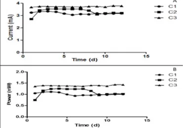
The results of current generation indicated that all three MFCs produced more than 3mA with an average of up to 3.52mA after 12 days. In the same vein, power output from each of the MFCs was greater than 1mW, with an average power generation of 1.24mW after 12days of operation (Fig. 1).
Figure 1. Result of (A) current and (B) power output of the cascade over a 12 day period. Catholyte from the 3 MFCs were collected and mixed before analyses and use.
Previous research has shown that power output is a determinant of the quality of the synthesized catholyte (Merino et al, 2016). Higher power output in MFCs is expected to enhance the catholyte potency as a biocidal agent.
Results of pathogen analysis showed that all pathogens increased with the addition of PBS even at an increased pH of 10.2. However, significant reduction in number was recorded in all pathogens tested against neat catholyte of similar pH. This result suggests that pH was not the main or only parameter responsible for the biocidal properties of the catholyte (Fig. 2).
Figure 2. Bioluminescence measurement of pathogens exposed to neat (A) PBS (control- pH 10.2) and (B) catholyte (pH 10.2) over 180 minutes. RLU: Relative light unit
Results of bacteria kill curve analysis indicate that all the pathogens tested were susceptible to the antimicrobial properties of the catholyte with at least 3-fold order of magnitude reduction recorded. E. coli, S. Typhimurium DT104, S. Enteritidis PT4 were the most susceptible pathogens, with over 4-log reduction in pathogen numbers in 180 sec (Fig. 2). Overall, results showed that the unique composition of the catholyte brought about pathogen killing recorded in this study.
IV. CONCLUSION
This work has shown catholyte synthesized as a byproduct of the power generation process in urine fed MFCs as a possible bactericidal agent (due to its unique composition). Thus, the catholyte generated could be exploited as disinfectants in urinals thereby reducing the need for synthetic disinfectants. Although catholyte has a uniquely high pH, this has been shown not to be the main bactericidal property of the catholyte. More work is currently being conducted to analyze the composition of the catholyte produced from different ceramic-based MFCs.
ACKNOWLEDGMENT
This work is funded by the Bill and Melinda Gates Foundation. REFERENCES
1. Santoro C, Ieropoulos I, Greenman J, Cristiani P, Vadas T, Mackay A, et al. Power generation and contaminant removal in single chamber microbial fuel cells (SCMFCs) treating human urine. Int J Hydrogen Energy. 2013;38(26):11543– 51.
2. Walter XA, Stinchcombe A, Greenman J, Ieropoulos I. Urine transduction to usable energy: A modular MFC approach for smartphone and remote system charging. Appl Energy [Internet]. 2016;4–10. Available from: http://dx.doi.org/10.1016/j.apenergy.2016.06.006
3. Santoro C, Arbizzani C, Erable B, Ieropoulos I. Microbial fuel cells: From fundamentals to applications. A review. J Power Sources [Internet]. 2017;356:225–44. Available from: http://dx.doi.org/10.1016/j.jpowsour.2017.03.109
4. Merino I, Greenman J, Ieropoulos I. Electricity and catholyte production from ceramic MFCs treating urine. Int J Hydrogen Energy [Internet]. 2016;42(3):1–9. Available from: http://dx.doi.org/10.1016/j.ijhydene.2016.09.163 5. Gajda, Iwona, John Greenman, Chris Melhuish, and Ioannis
Ieropoulos. 2015. “Simultaneous Electricity Generation and Microbially-Assisted Electrosynthesis in Ceramic MFCs.” Bioelectrochemistry 104:58–64. Retrieved (http://dx.doi.org/10.1016/j.bioelechem.2015.03.001).
B A
![Fig. 1. Thickness of the interlayers of the analysed AS-SOFC (left) and its microstructure (right) [1]](https://thumb-eu.123doks.com/thumbv2/123dokorg/5589590.67285/73.892.468.835.770.875/fig-thickness-interlayers-analysed-sofc-left-microstructure-right.webp)
