i
INGEGNERIA
__________________________________________________________
SCUOLA DOTTORALE / DOTTORATO DI RICERCA IN
XXVI
_______________________
CICLO DEL CORSO DI DOTTORATO
Lifetime investigations on Novel Thermal Barrier Coating systems for Gas Turbine
applications
______________________________________________________
Titolo della tesi
Ahmed Umar Munawar
__________________________
__________________
Nome e Cognome del dottorando
firma
Prof. Ing. Giovanni Cerri
_________________________
__________________
Docente Guida/Tutor
firma
Prof. Ing. Edoardo Bemporad
________________________
__________________
ii
Abstract
In this study, relatively new materials for ceramic top coat, bond coat and substrate applications are studied and their effect on the lifetime of TBC systems is investigated with the aim of increasing the temperature capabilities of gas turbines and/ or improving the lifetime of current TBC systems. The standard TBC system tested for comparison is IN100/ NiCoCrAlY/ 7YSZ. During the study, each component of the standard system is replaced by an relatively advance material and the effect on lifetime is investigated. The material tested for ceramic top coat material is Gadolinium Zirconate (GdZ) which is well known for its lower thermal conductivity and higher thermal stability. Recently, studies demonstrated very good resistance of GdZ against CMAS and volcanic ash attack. In a gas turbine application, with the internal cooling present, GdZ will definitely reduce the temperature at the underlying metal surface due to its lower thermal conductivity. The aim of this study is however to investigate the effect of GdZ on the lifetime of TBC systems. For substrate effect, IN100 superalloy is compared with a more advance, CMSX-4 superalloy. CMSX-4 is a 2nd generation, single crystal superalloy manufactured by Cannon Muskegon Corporation and is well known for its improved high temperature properties. To investigate the bond coat effect, the performance of standard NiCoCrAlY has been compared with a Hf- doped version of NiCoCrAlY deposited on CMSX-4 substrate. Furthermore, the effect of higher Y-content has also been investigated by doping the NiCoCrAlY bond coats with extra Y and depositing on IN100 substrate. All the depositions have been carried out by Electron- beam physical vapor deposition (EBPVD) techniques. The lifetime investigations have been carried out by furnace cyclic testing (FCT) where the TBC samples are kept at 1100°C for 50mins and are cooled down to room temperature by forced air cooling for 10mins. The whole experimental research for this study, from the deposition of samples to the microstructural analysis, has been carried out at German Aerospace Center (DLR) in Cologne, Germany.
This study showed that GdZ on NiCoCrAlY bond coat improves the lifetime of TBC systems considerably. This improvement of lifetime has been observed for both IN100 and CMSX-4 substrates. However, CMSX-4 and NiCoCrAlY based TBC systems show a lower lifetime than the IN100 based counterparts, irrespective of the ceramic top coat material. During thermal cycling, GdZ has been found to undergo a chemical reaction with the TGO on NiCoCrAlY bond coats and a new phase forms at the TBC- TGO interface. In the beginning, this new phase is formed in random patches at different locations, however, with increasing the number of thermal cycles; this new phase becomes continuous at the TBC- TGO interface. GdZ undergoes an ordering transformation from cubic fluorite to pyrochlore phase during thermal cycling. This pyrochlore phase has a very high thermal stability and is the main motivation behind using GdZ as ceramic top coat material. It has been observed that this fluorite to pyrochlore transformation is not detrimental for the lifetime of TBC systems as GdZ based TBCs show a very high lifetime despite this transformation.
iii
In case of NiCoCrAlY version with higher yttrium content, referred to as NiCoCrAlY-2 in this study, it was observed that Yttria forms at the TBC-TGO interface in the form of elongated islands even before the deposition of ceramic top coat. This yttria layer interacts with the TGO during thermal cycling and forms different Y- aluminates. When GdZ-NiCoCrAlY-2 TBC system is thermally cycled, the chemical reaction between GdZ and the TGO results in a reaction zone consisting of alternating Gd- and Y rich phases. GdZ-NiCoCrAlY-2 TBC systems show a significantly longer lifetimes, however, 7YSZ-NiCoCrAlY-2 TBC systems showed relatively shorter lifetime than the standard 7YSZ-NiCoCrAlY TBC systems.
The effect of Hf has also been investigated on CMSX-4 substrate. It has been observed that doping NiCoCrAlY bond coats with 0.6 wt. % Hf improves the lifetime by around 10 times. This improved lifetime doesn’t change much when the ceramic top coat is replaced from 7YSZ to GdZ. In the CMSX-4 based TBC systems, diffusion of refractory elements has been found from the substrate towards the TGO. In the NiCoCrAlY-Hf systems, additional diffusion of Hf is also observed and Hf can be seen at the TBC-TGO interface, in the TGO and in the bond coat. In this study, an attempt has been made to understand the mechanisms which effect the lifetime of TBC systems by investigating diffusion of elements in TBC systems, phase changes, chemical reactions and sintering effects.
iv
ACKNOWLEDGEMENTS
I would like to express my deepest gratitude to my supervisor Prof. Giovanni Cerri for all his technical guidance, his moral support, encouragement and patience. His kindness and cooperative nature helped me throughout my PhD and I’d like to carry these attributes in my life as well. I feel lucky to be a part of this research group at the University of Roma Tre and I am thankful to all my colleagues here for their support and cooperation.
I owe special thanks to Dr. Uwe Schulz from German Aerospace Center (DLR) where I carried out all my experimental research. With all his experience and knowledge in the field of Thermal Barrier Coatings, I could not have found a better supervisor than him. He supported me very well throughout my PhD and was always cooperative and understanding. In the end, he read and corrected my PhD thesis even when I was not a part of DLR. I am also thankful to my colleagues at DLR for all the good time I had over there.
I would like to thank my family as well especially my wife Nabawiya Mattke for her support. My children, Zainab and Daud, are source of inspiration for me and I always get motivation and energy when I look at them. My parents always encouraged and motivated me for higher education and I would like to give special gratitude to them for all their unconditional love and support. Without the support of my family, I could never have accomplished so much in my life.
v
CONTENTS
1. INTRODUCTION AND MOTIVATION ……… 1
2. LITERATURE SURVEY………. 4
2.1.TBC System ………...………..….. 4
2.2.Substrate ………...………..…… 4
2.3.Bond Coat ……….…...…………..………. 7
2.3.1. Overlay coatings as bond coats ……….………. 8
2.3.2. Effect of reactive elements on oxide scale adhesion ……….………. 9
2.4.Thermally Grown Oxide ………...……. 11
2.5.Ceramic Top Coat ……….. 13
2.5.1. Yttria Stabilized Zirconia ……….. 14
2.6.Coating Processes ………... 15
2.6.1. Plasma Spray Deposition ………... 15
2.6.2. Electron Beam Physical Vapor Deposition ……….... 16
2.6.3. Effect of Coating Process on TBC properties ……….... 18
2.7.Microstructure of EB-PVD Coatings ………. 20
2.8.New Materials for Ceramic Top Coat ……….... 21
2.8.1. Zirconia Based Compositions ……… 21
2.8.2. Pyrochlores ……… 23
2.8.3. Perovskites ……….……… 25
2.9.Sintering of Ceramic Top Coat ………...………..…. 25
2.10. Failure Mechanisms of TBC systems ……….. 26
2.10.1. TGO growth and Residual Stresses ………... 27
vi
2.10.3. Rumpling and Ratcheting ………. 28
2.10.4. Mud Cracking ………... 29
2.10.5. Chemical Failure ……….. 30
3. Experimental Procedure ………. 31
3.1.Different Materials for TBC systems ………... 31
3.2.Bond Coat Deposition ……….. 32
3.3.Ceramic Top Coat Deposition ……….. 33
3.4.Furnace Cyclic Testing ………... 34
3.5.Metallographic Preparation ……….. 34
3.6.SEM and EDX Measurements ………. 35
3.7.X-ray Diffraction ………. 35
4. Results ……… 36
4.1.IN100 based TBC systems ………... 36
4.1.1. IN100-NiCoCrAlY-7YSZ system ……… 36 4.1.1.1.TGO Microstructure ………... 36 4.1.2. IN100-NiCoCrAlY2-7YSZ system ……….. 38 4.1.2.1. Effect on lifetime ………. 38 4.1.2.2. TGO Microstructure ……… 38 4.2. CMSX-4 based TBC systems ……….. 39
4.2.1. CMSX-4- NiCoCrAlY- 7YSZ system ……….40
4.2.1.1. Diffusion of Elements ………. 40
4.2.2. CMSX-4- NiCoCrAlY-Hf- 7YSZ system ………... 42
4.2.2.1 Lifetime results ……… 42
vii
4.2.2.3 Diffusion of elements ………. 47
4.3. Gadolinium Zirconate as Ceramic top coat material ………. 48
4.3.1 Phase changes during thermal cycling ………... 49
4.3.2 Double-layer GdZ TBCs ……… 50
4.3.3 Sintering of GdZ ……… 51
4.4. GdZ on different TBC systems ……….. 55
4.4.1 Effect on lifetime ………... 55
4.4.2 Effect on TGO microstructure ………... 56
4.5. Failure Mechanisms and Failure location .……...………. 61
4.6. TGO Growth ………. 66
5. Discussion ………. 69
5.1. Lifetime investigations ……….. 69
5.1.1 Ceramic top coat effect ……….. 69
5.1.2 Bond coat effect ………. 70
5.1.3 Substrate effect ……….. 72
5.2. Morphology of ceramic top coat materials ……… 74
5.3 Sintering and Phase changes ……….. 75
5.4 TGO Microstructure ……….. 76
5.4.1 IN100 based TBC systems ………. 78
5.4.2 CMSX-4 based TBC systems ……… 81
5.5 Ceramic top coat effect on TGO………. 82
5.6 Failure mechanism and location ………….………... 86
5.7 TGO growth ………... 88
viii
7. Future Work ………. 94 8. References ……… 95
ix
List of Figures
Fig. 1.1: Schematic diagram of Rolls Royce Trent 800 engine, which powers the Boeing 777 aircraft.
Fig. 1.2: Effect of TBC system on the temperature capabilities of gas turbines. Fig. 2.1: A schematic diagram of TBC system.
Fig. 2.2: The evolution of superalloy microstructure and the improvement in temperature capability [16].
Fig. 2.3: FCC phases in Ni-base superalloys, a) γ- Ni matrix and b) γʹ- Ni3Al [15].
Fig. 2.4: Relative oxidation and corrosion resistance of high temperature coating systems [23]. Fig. 2.5: Diffusion of reactive elements through bond coat [29].
Fig. 2.6: SEM micrograph of a NiCoCrAlY top view after annealing for 4hrs at 1080°C. Different phases identified by EDX are mentioned [47].
Fig. 2.7: Relevant part of yttria- zirconia phase diagram Fig. 2.8: Schematic diagram of Plasma spraying process [58]. Fig. 2.9: Schematic diagram of EB-PVD process [59]
Fig. 2.10: Vapor pressure of different oxides for EB-PVD process [54]. Fig. 2.11: Microstructures resulting from different deposition processes.
Fig. 2.12: Movchan model for the effect of substrate temperature on the microstructure of EB-PVD columns [76].
Fig. 2.13: Thermal conductivity values for different zirconia-based materials [89]
Fig. 2.14: Suggested GdO1.5ZrO2 binary phase diagram constructed from a summary of the
literature data [107].
Fig. 2.15: Cyclic lifetime of Ln-zirconate and Gd- zirconate based single and double-layer TBC systems [101].
Fig. 2.16: Schematic diagram showing the buckling failure mechanism [151, 153].
Fig. 2.17: A comparison of two identical diffusion bond coats without bond coat, a) after 100 x 1 h thermal cycles at 1150°C and b) after 100 h isothermal heating at 1150°C [153, 161].
x
Fig. 3.1: 60 kW LEYBOLD ESC equipment for EV-PVD deposition. Fig.3.2: 150 kW EB-PVD plant with 2-beam evaporation source. Fig.3.3: Furnace cyclic testing set up.
Fig 4.1: Morphology of as-coated EB-PVD columns of 7YSZ.
Fig 4.2: TGO microstructure of 7YSZ-NiCoCrAlY- IN100 system in a) as-coated condition [67] and b) after 2000 cycles.
Fig. 4.3: Average lifetime values of NiCoCrAlY and NiCoCrAlY-2 based TBC systems with IN100 as the substrate and 7YSZ as the top coat material.
Fig. 4.4: TGO microstructure of IN100- NiCoCrAlY-2-7YSZ system in a) as-coated condition and b) after 1300 cycles.
Fig. 4.5: EDX measurement showing a) the location where EDX measurement is done, b) total refractory content after different thermal cycles and c) individual refractory elements present in the bond coat after 569 cycles [187].
Fig. 4.6: XRF result highlighting the major peaks of Ta, W, Re and Al in CMSX-4 and 7YSZ based TBC system spalled after 569 cycles.
Fig. 4.7: Lifetime comparison of NiCoCrAlY bond coat system with NiCoCrAlY-Hf system when CMSX-4 has been used as substrate and 7YSZ has been used as top coat material. Fig. 4.8: TGO microstructure of NiCoCrAlY-Hf system in the as-coated condition.
Fig. 4.9: TGO microstructure after 100 cycles on a) standard NiCoCrAlY bond coat and b) NiCoCrAlY-Hf bond coat.
Fig. 4.10: TGO microstructure of Hf-added system after thermal cycling for a) 200 cycles and b) 2500 cycles.
Fig. 4.11: TGO microstructure of Hf- added NiCoCrAlY system after a) 500 cycles and b) after 3000 cycles.
Fig. 4.12: Refractory content in the bond coat near to the TGO after 100 cycles and after 3000 cycles.
Fig. 4.13: a) GdZ columns in the as-coated condition and b) column tips of GdZ columns in the as-coated condition.
Fig. 4.14: XRD plot of as-coated GdZ (milled), sintered for 2hrs at 1260°C (coating) and after 2850 cycles (milled).
xi
Fig. 4.15: a) SEM Micrograph of a double layer GdZ TBC in the as-coated condition and b) lifetime values of single and double layer GdZ TBC compared with standard 7YSZ system. Fig. 4.16: GdZ- 7YSZ columns interface in a) the as-coated condition and b) after thermal cycling for 635 cycles.
Fig. 4.17: SEM micrograph showing the tip of the columns a) as-coated GdZ columns tip, b) GdZ after 2000 cycles and c) 7YSZ after 3000 cycles.
Fig. 4.18: Top-view of a) as-coated GdZ columns and b) GdZ columns after 5000 cycles. Fig. 4.19: Lifetime comparison of GdZ vs. 7YSZ on NiCoCrAlY-Hf and CMSX-4.
Fig. 4.20: TBC- TGO interface of IN100-NiCoCrAlY-GdZ TBC system after thermal cycling for a) 685 cycles and b) after 5000 cycles.
Fig. 4.21: TGO microstructure of GdZ-NiCoCrAlY-CMSX-4 TBC system in a) the as-coated condition and b) after thermal cycling for 980 cycles.
Fig. 4.22: Al diffusion in GdZ- NiCoCrAlY TBCs after thermal cycling for 685 cycles. Fig. 4.23: TBC-TGO microstructure for GdZ- NiCoCrAlY-2 TBC system on IN100 substrate. Fig. 4.24: TBC-TGO microstructure for GdZ- NiCoCrAlY- Hf TBC system on CMSX-4 substrate after 3000 cycles.
Fig. 4.26: Failure location of a GdZ- NiCoCrAlY-2 system where a thin TBC layer remains intact with the TGO after TBC failure.
Fig. 4.27: Failure pattern of a) CMSX-4-NiCoCrAlY-7YSZ system, b) CMSX-4-NiCoCrAlY-Hf-7YSZ system and c & d) CMSX-4-NiCoCrAlY-GdZ system.
Fig. 4.28: a) Macroscopic failure pattern of GdZ- NiCoCrAlY-Hf system and b) failure location of GdZ- NiCoCrAlY-Hf TBC.
Fig. 4.29: TGO growth for different TBC systems tested in this study.
Fig. 4.30: Fig. 4.30: a) TGO thickness measurement for the NiCoCrAlY-Hf based TBC systems and b) TGO growth of NiCoCrAlY-Hf based TBC systems with 7YSZ and GdZ as top coat materials.
Fig. 5.1: Lifetime vs Hf- content in NiCoCrAlY bond coat on CMSX-4 substrate. Fig. 5.2: Diffusion of refractory elements from the substrate towards the bond coat. Fig. 5.3: Ellingham diagram of some oxides modified from Birks and Meier [17].
xii
Fig. 5.4: mixed zone in NiCoCrAlY2 bond coat system. Fig. 5.5: Ternary phase diagram of YO1.5, AlO1.5 and ZrO2.
Fig. 5.6: Isothermal sections at 1250°C for AlO1.5-GdO1.5-ZrO2 system [108].
Fig. 5.7: Isothermal sections of AlO1.5-GdO1.5-YO1.5 system at 1200°C [184].
Fig. 5.9: Tensile stresses due to the inter-columnar sintering in GdZ columns Fig.5.10: TGO growth through the reaction phase for GdZ-NiCoCrAlY systems.
xiii
List of Tables
Table 2.1: Some properties of the main alumina isoforms [153] Table 3.1: Composition of different materials used in this study.
Table 6.1: Average lifetime, upper temperature limit and the dominating failure pattern for various TBC systems investigated in this study.
xiv
Nomenclature (List of Abbreviations)
TBC = Thermal Barrier Coatings
EB-PVD= Electron Beam Physical Vapor Deposition PS = Plasma Spraying
RE = Reactive Elements DS = Directionally solidified SC = Single crystal
GdZ = Gadolinium Zirconate
7YSZ = 7 wt % yttria stabilized zirconia TGO = Thermally Grown Oxide
CMAS = Calcium Magnesium Alumino Silicates DySZ = Dysprosia stabilized Zirconia
CeSZ = Ceria stabilized Zirconia FCT = Furnace Cyclic Testing XRF = X-ray Fluorescence XRD = X- ray Diffraction
SEM = Scanning Electron Microscopy
xv
DEDICATION
1
1- Introduction and Motivation
A gas turbine is an internal combustion engine that is used to deliver mechanical power and/ or thrust. It consists of three main parts which are 1- compressor, 2- combustion chamber and 3- turbine or expander. A compressor increases the pressure and temperature of inlet air to 200- 600°C and directs it towards a combustion chamber [1]. The fuel is introduced in a highly atomized spray form in the combustion chamber and the compressed air/ fuel mixture is ignited thereby creating a gaseous product which is very high in stored energy and exists at a very high temperature. These gases are directed to the turbine section which converts the stored energy in the gas to rotational mechanical energy of the turbine rotor. In aircraft engines, these gases can be fed through another set of nozzles in the exhaust of the turbine to convert even more energy to thrust, and the use of an afterburner can increase thrust even further in military applications. A gas turbine for jet engine application is shown in Fig. 1.1.
Fig. 1.1: Schematic diagram of Rolls Royce Trent 800 engine, which powers the Boeing 777 aircraft [2].
The efficiency of all types of a gas turbine engines (aircraft, terrestrial and marine) is strongly dependent on the turbine inlet temperature (TIT). From a performance standpoint, stoichiometric combustion with turbine inlet temperature of around 2,000°C would be a thermodynamic ideal as no work would be “wasted” to compress air needed to dilute combustion products [3, 4]. As a result, the current industry trend pushes the turbine inlet temperature closer to the fuel
Fan
Low Pressure Compresor
Combustor
High Pressure Turbine Low Pressure Turbine
Thrust
Thrust Air Inlet
High Pressure Compresor
Twin Spool Shaft Fan air bypassing
2
stoichiometric temperature, especially for military aircraft engines. However, allowable component metal temperatures, even for the most advanced alloys and manufacturing processes, cannot exceed 1000°C. To operate gas turbines at gas temperatures well above this limit, a highly efficient cooling system is required. Improvement in cooling technology is very important to achieve higher turbine inlet temperatures. For advanced aero engines turbine inlet temperatures (TIT) close to 1700°C and compressor pressure ratios around 40:1 are becoming a reality [4]. For industrial engines the major requirement is long-term durability without frequent inspections and overhauls. The TIT limit for a modern industrial gas turbine is established presently in the range of 1250- 1400°C and the components are expected to endure at least 30000 hours between overhauls, with potential to be repairable such that the engine life can be extended to 100,000 hours [4, 5].
The most common cooling techniques are based on the application of the air bled from the compressor discharge or intermediate stages. Introduction of this turbine cooling air results in degradation of turbine performance because less work is extracted from the compressed cooling air. At the same time there is lesser amount of air available for the combustor which makes liner cooling and emission control more difficult. The major challenge in designing such a cooling system is to achieve targeted metal temperature by a minimum amount of cooling air and to produce the smallest negative impact on engine durability, performance, weight, emission, cost, and fabrication complexity. Another type of cooling technique is to allow the coolant to penetrate the airfoil surface through a porous wall. This is a very efficient air cooling technique available but it has significant limitations due to required small size of the pores and the potential problem of their blockage. However to minimize these problems, the cooling air can be discharged through relatively large holes mixing subsequently with a relatively small velocity mainstream flow [4].
The use of coatings in the protection of underlying metal from high temperature degradation has been seen as important for the last 100 years [6, 7]. There has been a significant development in coatings technology and composition since then. The first coating for protection against high temperature was an early form of aluminium diffusion coating and was patented by Van Aller in 1911 [6]. The first use of coating in gas turbines was in 1942 by Anselm Franz who aluminized low alloy steel to substitute more expensive high alloy steels. Use of both ceramic and metallic coatings to increase the turbine inlet temperature even further was first use in military aircrafts. These advancements were then passed down to civil aero engine applications and led to a significant increase in engine efficiency through reduction of internal cooling requirements [7-9]. This combination of ceramic and metallic coatings to withstand high temperature in gas turbines is called Thermal Barrier Coating (TBC) system. TBC coatings allow gas turbines to operate at a higher temperature, as shown in Fig. 1.2.
3
Fig. 1.2: Effect of TBC system on the temperature capabilities of gas turbines [10].
These days film cooling is frequently used in combination with previously mentioned cooling techniques to provide cooling for gas turbine components. The coolant flowing through the internal sections of the turbine blades remove the heat flowing from the metal. In the internal convection heat transfer phenomena; flow velocity and composition of the coolant gas and, architecture and geometry of the blades play the most important part. Between the ceramic and metallic layers of the TBC system, conduction heat transfer takes place which depends mainly on the thermal conductivity and thickness of ceramic top coat. A lower thermal conductivity and a higher thickness of ceramic top coat layer will definitely reduce the temperature at the underlying metal surface. Apart from thermal conductivity, higher thermal stability of the ceramic top coat is also very important to operate the gas turbines at higher TIT.
The aim of this study is to investigate the mechanisms affecting the lifetime of relatively new TBC systems. In this study gadolinium zirconate (GdZ) is studied as the ceramic top coat layer which is well known for its higher thermal stability and lower thermal conductivity. GdZ is deposited on different bond coats and substrate materials and lifetime investigations are carried out at elevated temperature.
4
2- Literature Survey
2.1
TBC System
Together with internal cooling, TBC systems allow gas turbines to operate at a higher temperature and/ or improve the lifetime of components. In TBC systems, a metallic and a ceramic coating is deposited on the base or substrate material which is usually a Ni or Co based substrate to withstand high temperature, stress, and high temperature oxidation & corrosion conditions in gas turbines. A TBC system is shown schematically in Fig. 2.1.
Fig. 2.1: A schematic diagram of TBC system [5].
During the deposition of ceramic top coat, an oxide layer starts to grow at the interface of ceramic top coat and bond coat. During the operation of TBC system this oxide layer continues to grow and as a result stresses accumulate in the TBC system, which play an important role in the failure of TBC system. Different components of a TBC system are explained in detail in the upcoming sections.
2.2
Substrate
High temperature nature of the applications requires the use of superalloys to make various components of gas turbines. Usually, the high temperature is defined from the aspect of material rather than that of the application itself. For this reason, it is important to mention the fraction of melting temperature Tm, also called the homologous temperature, of the alloys used. Superalloys
are those which have the capability to operate in excess of 0.5Tm. Ni- based superalloys are
well-known for their outstanding combination of high temperature strength, toughness and resistance to degradation in corrosive or oxidizing environments [11]. Therefore turbine blades, which are a critical component in both aeronautical and stationary gas turbines, are made from Ni- base
5
superalloys. As the performance of gas turbines is closely related to the capability of materials to withstand high temperatures, there has been a tremendous development in superalloys. Ni- base superalloys have a γ phase matrix with a face- centered cubic (FCC) structure, containing a dispersion of intermetallic precipitate particles of γʹ- Ni3Al [11].
In the beginning, superalloys were cast with equiaxed structure with a higher γʹ volume fraction in order to improve the creep strength at higher temperatures. The grain boundaries of these equiaxed superalloys were strengthened by adding the elements C, B, Zr or Hf [12]. it was observed that the grain boundaries represent the weak points in the system. In 1960s, the creep strength and ductility were significantly improved by the elimination of grain boundaries perpendicular to the principal stress axis, by means of directionally solidified (DS) blades [12, 13]. In DS blades, the columnar grains are aligned to the blades axis, as shown in Fig. 2-2. It is because the major failure mechanisms for turbine blades involved nucleation and growth of cavities along transverse grain boundaries. DS blades improved the temperature capability of turbine blades by around 20°C, compared to the conventional cast alloys. Later development in the turbine blades resulted in a total elimination of grain boundaries as grain boundaries represented the weak points and stresses tend to concentrate there. Single crystal superalloys also eliminated the requirement of grain-boundary strengthening elements (C, B, Zr, Hf). The evolution of turbine blades cast in different microstructures is shown in Fig. 2.2.
Single crystal superalloys represent the best microstructure; industry has to offer currently, where strength is considered. However, there has been tremendous development in single crystal superalloys with respect to high temperature properties and at the same time the composition has become more complicated [13-15]. The first original modification of SC superalloy chemistry has been the introduction of rhenium (Re). This refractory element imparts significant creep advantages over the 1st generation superalloys due to solid solution strengthening effects [15]. In addition Re, due to its low diffusion rate, slows down all thermally activated mechanisms controlling the high temperature deformation and damage mechanisms. Rene N5, CMSX-4 and PWA1484, which have been developed by General Electric, the Cannon Muskegon Corporation and Pratt & Whitney respectively, are typical example of 2nd generation superalloys containing about 3wt. % Re. These three superalloys are widely used these days in a variety of aircraft engines as well as in land-based gas turbine engines for power generation. Further increase of Re content to about 6wt. % leads in the development of third generation superalloys such as Rene N6 and CMSX-10 by General Electric and Cannon Muskegon Corporation respectively. However, the addition of Re is not a panacea as it also imparts some drawbacks such as high cost, limited availability, increase of the density and higher proneness to deleterious topologically close-packed (TTP) phase precipitation [14]. To overcome these problems from the 3rd generation superalloys, addition of Ruthenium (Ru) has been found to be useful which has also become a basis for the latest 4th generation superalloys [14, 15].
6
Fig. 2.2: The evolution of superalloy microstructure and the improvement in temperature capability [16].
Strengthening mechanisms used for Ni- base superalloys are precipitation and solid- solution hardening. In precipitation hardening, the solute atoms precipitate in creating a fine and uniformly dispersed second phase. In Ni- base superalloys precipitation hardening is the most important mechanism where γʹ Ni3Al precipitates provide the most important mechanism for
strengthening by acting as coherent barrier to dislocation movement. The creep resistance is dependent on slowing the dislocations speed within the crystal structure. There are many elements (such as Ti, Ta, Al, Mo etc.) which promote the creation of γʹ phase. The size of γʹ phase particles can be precisely controlled by careful precipitation hardening heat treatments. Many modern superalloys consist of square γʹ particles finely dispersed in γ matrix. The γʹ- Ni3Al phase is not strictly stoichiometric as the Ni sites may also contain Co, Cr, Re, W and Mo,
while Al sites may contain Ti and Nb. Strengthening by γʹ precipitates is attributed to the slight structural difference between the γ and γʹ phases i.e. long range order and lattice misfit. Dislocations can only move through γʹ precipitates in pairs, called superdislocations. The energy required for the superdislocation to pass through γʹ precipitates is called anti-phase boundary
7
(APB) which is a result of different slip planes between the two phases [2]. Modern superalloys may contain up to 70 % volume fraction of γʹ phase for the purpose of strengthening. These γʹ precipitates are distributed homogeneously in the γ matrix and have sizes less than 1µm [14].
Fig. 2.3: FCC phases in Ni-base superalloys, a) γ- Ni matrix and b) γʹ- Ni3Al [15].
2.3
Bond Coat:
Bond coat gets the name from its function of providing bonding between the ceramic top coat layer and the metallic substrate in a TBC system. It is also supposed to provide necessary protection against hot oxidation and corrosion by forming a protective oxide film which is mostly alumina. Chromia has been another protective oxide which is used for protection at temperatures between 600-900°C in many applications such as catalytic converters [8, 17, 18]. However, it tends to evaporate above 1000°C and hence it is not used for such applications. As explained in previous section, the refractory content of substrate material has been increased continuously over the recent years to improve its strength. This has resulted in a decrease in the Al and Cr content which is harmful for the oxidation and corrosion resistance of superalloy substrates for long term applications. Consequently, it is very important to deposit a bond coat layer which protects the underlying substrate material against high temperature oxidation and corrosion by forming a suitable oxide layer. The structure and composition of this oxide layer which is called thermally grown oxide (TGO) depends on the bond coat material and plays a very important role in determining the lifetime of TBC systems.
The earliest coatings used for protection against hot oxidation and corrosion have been diffusion aluminide coatings based on intermetallic compound NiAl [19-22]. These coatings have enough reservoir of Al to form Al2O3 at high temperature. However, major limitations of these coatings
are their lack of ductility at temperatures below 600°C and a considerable reduction in the lifetime above 950°C [8]. With the passage of time, many alloying additions have been made in NiAl coatings to improve their properties and lifetime. Espe8cially, with the addition of Pt in
8
NiAl coatings, the lifetime has been improved significantly. PtAl bond coats are usually manufactured by electroplating a thin layer of Pt on the superalloy and then aluminizing by chemical vapor deposition (CVD) technique or by pack cementation process. The other type of bond coats are overlay coatings, which will be discussed in detail in the upcoming section. The thickness of a bond coat is usually in the range of 75- 150µm.
2.3.1
Overlay Coatings as Bond Coats
Overlay coatings are based on MCrAlY (where M = Ni, Co or a combination of these) and are deposited by low-pressure plasma spraying (LPPS) or by physical vapor deposition (PVD) techniques. Overlay coatings are about 2-4 times more expensive than the diffusion processes; however, much better control on the coating composition can be achieved since the composition is dictated by the coating source. This provides flexibility in depositing different bond coat compositions, however, knowledge of vapor pressure, deposition efficiency and spatial distribution of all the chemical elements is required [23].
MCrAlY coatings are composed of Al- rich and finely divided β-NiAl precipitates in γ-Ni(Co, Cr, Al)- solid solution. This β phase acts as Al- reservoir during the TGO growth at high temperature. As in case of superalloy, the different elements present in the bond coat also serve different roles. Nickel being the element in majority, reduces the phenomenon of inter-diffusion with substrate material. Aluminum provides a reservoir to constantly replenish the oxide during the working of a TBC system. Chromium promotes the formation of α-alumina which is stable at higher temperature and has a very low diffusivity of oxygen resulting in a slow TGO growth. The oxidation of MCrAlY coating is directly proportional to the formation rate of continuous alumina scales present on its external surface. The rate of formation of the scale is related to aluminum activity. Cr also plays an important role in increasing the aluminum activity. Further, the addition of Cr effectively lowers the aluminum content required to form and maintain the oxide film. Overlay coatings can be Ni or Co based, depending upon their applications. Generally, at higher temperatures where oxidation is dominant failure mode (900°C), Ni based over-lay coatings are preferred while for applications at 650-800°C, where corrosion is dominant failure mode, Co- based overlay coatings outperform Ni- based ones because of their higher Cr content [24]. Composition of different overlay coatings according to their application is shown in Fig. 2.4.
9
Fig. 2.4: Relative oxidation and corrosion resistance of high temperature coating systems [23].
2.3.2
Effect of Reactive elements on Oxide Scale Adhesion
Reactive elements (REs, e.g., Y, Zr, Hf etc.) are frequently added in overlay coatings to improve adhesion of coatings, however, their role is still not completely understood [27-31]. The addition of Yttrium to the coating promotes scale adhesion. Y has limited solubility in MCrAlY, therefore the excess quantities precipitate within grain boundaries as yttria. This yttria forms pegs, which protrude into the coating alloy and its surface scale. The coating alloy and the alumina film are thus mechanically pinned together and hence scale adhesion is improved [5, 25, 26]. Hf has been found to form oxide stringers in the bond coat and thus improves the coating adhesion by causing an “anchoring” effect. It has been demonstrated that Hf reduces growth rate of alumina scale by a factor of 10 and this reduction has been explained by suppression of Al- grain boundary transport by the segregation of RE ions to the grain boundaries [32]. As a result, such thinner scales can significantly improve scale adhesion as the strain energy release rate upon cooling is direction proportional to the scale thickness. RE in bond coats also increase the oxide scale plasticity and hence result in improve the oxide scale adhesion. However, a contrary result has been reported
10
where a faster TGO growth has been reported because of Hf- doping of NiCoCrAlY [33]. It has been mentioned that the diffusion through NiCoCrAlY bond coat deposited by Electron Beam Physical Vapor Deposition (EB-PVD) method is faster because of relatively fine-grained structure of NiCoCrAlY [33].
It has been demonstrated that reactive elements segregate at the grain boundaries of TGO and limit the outwards diffusion of Al [34]. As a result there is a change in the rate-limiting step of oxidation and in oxide microstructure and oxide grain size is reduced. It has been proposed in some studies that reactive elements segregate at the metal-oxide interface and grain boundaries as shown in Fig. 2.5 and inhibit interfacial void growth, thus improving the oxide scale adhesion [30, 34, 35].
Fig. 2.5: Diffusion of reactive elements through bond coat [29].
In one of the studies, adhesion between different ceramic/ metal interfaces has been measured and it was observed that Zr, Ti, Y, Si and Sc improve the adhesion between Ni/ Al2O3 interface
[24]. It has also been mentioned that Hf doping to the bond coat can considerably improve the adhesion between bond coat and TGO [36, 37]. Some mechanisms to improve oxidation resistance by reactive elements addition have been stated in the literature which are; enhanced oxide-scale plasticity, a graded seal mechanism, modification of the oxide’s growth process, chemical bonding, a vacancy sink model and “pegging” by other oxides [24].
11
Apart from oxidative corrosion, sulfur also reduces the adhesion at alloy/ oxide interface. It enhances pore formation by lowering its nucleation energy and weakens the interface by accelerating crack propagation between pores [38]. Addition of RE also lowers the extent of sulfur segregation at the metal/ oxide interfaces and hence improves the oxide adherence. It has been stated that Y reacts with the indigenous S to form stable sulfide, thus preventing S from degrading the scale adhesion [5, 39]. In another study, Y-segregation at the alloy-oxide interfaces has been mentioned which lowers the driving force for sulfur segregation at these interfaces and thus eliminates its detrimental role. Apart from Y; Ta, Zr and Hf have also been reported to form pegs which improve the adherence between metal/ oxide interface.
2.4
Thermally Grown Oxide
At high temperature, an oxide film starts to grow at the interface of the bond coat and the ceramic top coat and is called thermally grown oxide (TGO). TGO serves the purpose of protecting the underlying bond coat from further damage, however, it is also a source of strain incompatibility between the different layers of a TBC system. Due to its continuous growth, stresses accumulate at the TGO- bond coat and TGO- ceramic top coat interfaces which play an important role in the failure of TBC system. The composition and structure of TGO depends mainly on the bond coat. An ideal bond coat is engineered so that the TGO forms as α- alumina and that its growth is slow, uniform and defect free [5]. Such a TGO has a very low ionic diffusivity and is quite stable at high temperature. In general, the growth of TGO takes place by inward diffusion of oxygen [40, 41] however in some cases outward diffusion of Al also becomes important [42, 43]. At high temperature, the formation of θ- and/ or γ Al2O3 and its conversion to the stable α-Al2O3 in the TGO has been mentioned to have a profound effect on the structural integrity of the TGO during thermal cycling [44, 45]. Some properties of different isoforms of alumina are mentioned in Table 2.1.
Table 2.1: Some properties of the main alumina isoforms [153]
α- alumina γ- alumina θ- alumina
Structure Rhombohedral Monoclinic Modified FCC
Density (Kg/m3) 3980-3990 3560-3600 3200-3700
Melting Point (°C) 2051
Transition Temperature (°C) Transition to α-
alumina ~925
Transition to δ- alumina 700-800
12
Thus annealing of bond coats prior to the ceramic top coat deposition is done to obtain an “optimum” TGO that only consists of α-Al2O3 so that the reliability and durability of TBCs are improved [46]. However, it has been reported in [47] that the only element to oxidize upon vacuum annealing of a NiCoCrAlY bond coat at 1080°C for 4hrs is yttrium. Formation of yttria after 4hrs of annealing prior to ceramic top coat deposition is shown in Fig. 2. 6.
Fig. 2.6: SEM micrograph of a NiCoCrAlY top view after annealing for 4hrs at 1080°C. Different phases identified by EDX are mentioned [47].
It has been reported that formation of yttria doesn't take place for the annealing temperatures below 1050°C [47]. Therefore, the formation of alumina or yttria as a result of annealing depends upon the temperature at which annealing is done. Further, TBC systems where vacuum annealing prior to ceramic top coat deposition is done above 1050°C showed a higher lifetime than the systems where vacuum annealing is done below 1050°C, which clearly shows the benefit of depositing ceramic top coat after yttria is formed at the interface [48] . As deposition of ceramic top coat is done on a pre-heated substrate, the yttria islands formed during the vacuum annealing step lose direct contact with the bond coat due to the formation of NiAl2O4
spinel layer below the yttria islands [46]. The relatively higher oxygen partial pressure and the steady temperature ramp covering the range from the room temperature to 1000°C within 10mins favor the formation of transient oxides such as spinels at this stage otherwise NiCoCrAlY system is known as a strong alumina former [49]. Till the deposition of ceramic top coat, TGO is approximately 0.5µm thick corundum layer including a periodic sequence of plug-shaped Y- rich
13
precipitates at the TGO- TBC interface at a spacing of approximately 1- 1.5µm. As the TGO transforms from metastable θ- and/ or γ Al2O3 to the stable α-Al2O3, the excess zirconia
precipitates out. This mixture of dark alumina with white zirconia particles is called a mixed zone. However, the convoluted TGO sections below the yttria islands contain very few zirconia particles, as the pure yttria islands act as a diffusion barrier restricting zirconia supply to the TGO. Such a discontinuous mixed zone structure is termed as “off-plane” mixed zone in the literature. Below the mixed zone, TGO grows in the form of columns and this region is also called columnar alumina zone (CAZ). The growth kinetics of the CAZ demonstrate protective diffusion- controlled parabolic or sub-parabolic growth rates which are typical for alumina- forming alloys. The thickness of the mixed zone, however, remains nearly constant over long periods [50].
2.5
Ceramic Top Coat:
Ceramic top coat is deposited on top of the bond coat to withstand high temperature and to cause a maximum possible temperature drop across its thickness by having very low thermal conductivity [51-54]. For the last two decades, different polymorphs of zirconia have been extensively studied for the ceramic top coat application. Zirconia, in its pure state, has extremely low thermal conductivity and relatively high strength and fracture toughness. In fact, the thermal conductivity of zirconia is lower than most of the other engineering ceramics by over an order of magnitude. In practical terms, this means that even a thin zirconia film (less than one millimeter thickness) can potentially reduce the temperature of the underlying alloy several hundred degrees Celsius when thermal gradient is there. Furthermore, the linear thermal expansion coefficient and elastic modulus of zirconia (especially the tetragonal phase) match very well to several popular nickel-based superalloys, compared to possible alternative ceramics. These properties play a very important role in surviving thermal cycling during TBC applications.
Zirconia exhibits polymorphism as a function of temperature and hence it has to be regulated in order to control its properties [55, 56]. Out of the monoclinic, tetragonal and cubic phases formed by zirconia over different temperature ranges, partial stabilization of tetragonal phase has been found to inhibit stress-induced micro crack propagations. Attempts have been made to control or eliminate the polymorphism by adding different oxides to zirconia. It has been observed that adding 6-8.5wt. % (~3-4.5mol.%) Y2O3 forms a partially stabilized tetragonal
phase while adding higher amounts of Y2O3 form fully stabilized cubic phase. Similarly, adding
CeO2, CaO or MgO also result in a fully stabilized zirconia. TiO2 as stabilizing oxide has been
found to be less effective, however, when added to Y2O3 or CeO2 stabilized ZrO2 has been shown
to produce zirconia polycrystals with favorable properties [5, 57]. Yttria-zirconia phase diagram has been shown in Fig. 2.6 with metastable Tʹ phase being highlighted.
During the initial TBC development during the 1970s, it has been demonstrated that addition of 6- 8.5wt. %(~ 3- 4.5 mol. %) Y2O3 gives the longest TBC lifetime in burner rig tests, even
14
though zirconia was not fully stabilized. This conclusion has been drawn with different test temperatures and different bond coat compositions. Time to first crack in thermal cycle tests as a function of Y2O3 content has been shown in Fig. 2.7. The lifetime of TBCs decreased
dramatically at concentrations exceeding these optimum values. It has to be pointed out that, after extensive research for the last two decades to identify better top coat compositions, 6-8 wt. %(~3-4.5 mol. %) Y2O3 content in ZrO2 continues to be optimum.
Fig. 2.7: Relevant part of yttria- zirconia phase diagram [23].
2.5.1
Yttria Stabilized Zirconia
Ceramic top coat material must possess a combination of properties to be effective. These properties include a low thermal conductivity, high coefficient of thermal expansion, better resistance to spallation, good erosion resistance, phase stability and pore morphological stability.
15
7 wt. % Y2O3 stabilized zirconia (YSZ) has very low thermal conductivity at elevated
temperatures (~2.3W.m-1.K-1 at 1273K for a fully dense material). 7YSZ has a high thermal-expansion coefficient (~11 x 10-6 K-1), which helps to reduce stress in TBC systems arising from the thermal-expansion mismatch between the ceramic top-coat and the underlying metal (~14 x 10-6 K-1) [5, 52]. To further alleviate these stresses, microstructural features like inter- and intra- columnar porosity and feather arms are deliberately engineered into the top-coat to make it highly compliant (elastic modulus ~ 50GPa) and “strain tolerant”. 7YSZ has a relatively low density (~6.4Mg.m-3), which is important to reduce the “parasitic-weight” in rotating engine components. 7YSZ also has a hardness of ~14GPa, which makes it resistant to erosion and foreign-body impact. It is resistant to ambient and hot corrosion and furthermore has a high melting point, making it suitable for high temperature applications.
2.6
Coating Processes:
Two most important methods used for TBC top-coat deposition are 1- plasma pray (PS) deposition and 2- electron beam physical-vapor deposition (EBPVD). These techniques will be discussed in detail in the upcoming sections.
2.6.1
Plasma Spray Deposition:
Plasma spray deposition is a type of thermal spraying which is extensively used because of its ability to deposit various compositions readily. In plasma spraying, the material to be deposited is introduced into the high temperature plasma gas stream in the form of powder. Spraying can be done under atmospheric or low pressure conditions. The molten powder particles are then carried into the plasma and propelled onto the substrate, which is heated to a controlled temperature in order to control stress. Thermal spraying processes are not practical for complex components with coatings required in narrow passages since it is a “line-of-sight” process. The advantages of thermal spraying are that it is relatively inexpensive, part size is not a concern, and deposition rates are high. The coating surface produced is, however, usually rough (an Ra of few
hundred) and subsequent finishing operations are usually required for airfoil aerodynamics. Plasma spraying can be used to deposit ceramic thermal barrier coatings, MCrAlY oxidation-resistant overlays and abradable seal systems in both the compressor and the turbine.
16
Fig. 2.8: Schematic diagram of Plasma spraying process [58].
2.6.2
Electron Beam Physical-Vapor Deposition:
Electron beam physical-vapor deposition (EBPVD) is a commonly used physical vapor deposition (PVD) technique in which an electron beam is used to melt and subsequently vaporize the solid ingot. High energy electron beam is produced by thermionic emission and is subsequently accelerated and concentrated by electromagnetic fields. During vaporization, a vapor cloud is formed which contains the atoms to be deposited. The substrate to be coated is mounted on to a sample holder and immersed in the area of vapor space where the vapors condense onto the substrate [59, 60]. The substrate is pre-heated to a controlled temperature to optimize coating residual stresses. EB-PVD process is shown in Fig. 2.9.
EB-PVD process results in a columnar microstructure of ceramic top coat where each column represents one grain. The final morphology and orientation of the columns depends on angle at which vapors condense on to the substrate. This is called vapor incidence angle (VIA) and represents the angle between the substrate normal and the average direction of vapor incidence. To control the vapor incidence angle, EB-PVD deposition can be carried out in perpendicular or oblique stationary mode, or conventional or oblique rotating mode. It has been observed that a fibrous column texture with mainly <111> and <110> preferred growth directions are achieved for coatings deposited by stationary perpendicular and oblique modes [59, 61]. However,
17
coatings deposited at different substrate temperature and rotation speed in conventional rotating mode exhibit a <100> column growth direction [62].
Fig. 2.9: Schematic diagram of EB-PVD process [59]
The complexity of the EB-PVD process vastly increases as the compositional complexity of the coating increases for example, in case of MCrAlY- type coating. It is because the vaporization pressures of each of the elements of interest must be considered in producing controlled alloy chemistry [63]. In addition, issues like melting and evaporation behavior of source material, deposition rate and efficiency and EB power and oxygen additions are also important in EB-PVD deposition [23]. As during the vapor phase processing, most of the compounds decompose into their individual constituents, it is important to consider the evaporation behavior of sub-oxides during the search for potential EB-PVD coating candidates. Fig. 2.10 shows the vapor pressure against different temperatures for some of the oxides currently in consideration for ceramic top coat materials.
18
Fig. 2.10: Vapor pressure of different oxides for EB-PVD process [54].
PVD processes are of a “line-of-sight” type and produce a coated surface which replicates the substrate surface, i.e. a smooth substrate surface initially will result in a smooth coated surface. In this way, subsequent coating finishing operations may be eliminated or minimized. Thickness uniformity and deposition rate are usually good but will vary with coating composition [63].
2.6.3
Effect of Coating Process on TBC properties:
The performance of a TBC coatings system depends on morphology of the ceramic top coat as well. This is evident from the properties of ceramic top coats when they are deposited with PS or EB-PVD techniques. Coatings deposited by PS have a thermal conductivity in the range of 0.8 – 1.0 W/mK at 25°C which is significantly lower than the 1.5 – 1.9 W/mK reported for EB-PVD coatings at 25°C [5, 64-66]. This means that the PS coatings provide superior thermal protection. However, the lifetime of PS TBC layers has been found to be lower than that of EB-PVD coatings which is mainly due to the higher strain tolerance of EB-PVD coatings [5, 23, 67]. Consequently, EB-PVD TBC layers are preferred for aerospace gas turbine applications.
The morphology of ceramic top coats is obtained when deposited with PS or EB-PVD techniques which results in different thermal and mechanical properties. In case of PS coatings, the microstructure mainly consists of “splats” which contain pores that are mostly aligned parallel to
19
the substrate surface. These pores are further accompanied by micro-cracks and fine grain boundaries as shown in Fig. 2.11.
Fig. 2.11: Microstructures resulting from different deposition processes [23].
In case of EB-PVD top coats, the microstructure consists of columnar grains which are separated to each other by inter-columnar porosity. There is also porosity present within the EB-PVD columns as shown in Fig. 2.11. The porosity present in EB-PVD coatings helps in improving the strain tolerance or compliance of EB-PVD coatings which leads to an improved lifetime. However, as inter-columnar pores are parallel to the thermal flux, such porosity doesn’t reduce the thermal conductivity as much as the pores perpendicular to the thermal flux do in case of PS coatings [5, 23, 54, 64, 66-69]. It has been mentioned that the thermal conductivity of ceramic top coat decreases as the pore volume fraction increases in case of PS coatings. It is because the pores provide a high impedance to heat flow through the thickness of coatings [5, 23, 66, 68, 69].
20
Further, PS coatings are believed to have a lower erosion resistance than EB-PVD coatings [70, 71]. On the other hand, PS coatings are less expensive than the EB-PVD coatings. Choice of PS or EB-PVD coatings is made after considering all the above mentioned characteristics.
2.7
Microstructure of EB-PVD Coatings
The early grains formed in EB-PVD process under both, conventional rotation and stationary, modes are of equiaxed type with no preferred crystal orientation [72-74]. This is assumed to be due to the low temperature of the substrate at the beginning of the EB-PVD process, thermal stresses at this state and interaction with the TGO. For conventionally rotated samples, the rotating movement dictates the crystallographic texture and morphology of the columns [75]. The microstructure consists of numerous single-crystal columns of fine diameter which start to grow on the equiaxed grains formed earlier. The growth of columns takes place continuously in a preferred growth direction enlarging their diameter and consequently reducing the number of columns due to a competitive growing process. Screening out of columns with unfavorable orientation allows a gradual broadening of favorable oriented ones. Due to the rotation of substrate, a “sunrise-sunset” line of sight shadowing effect takes place from the neighboring column which influences the favored growth of columns and impedes the vapor flux to reach the bottom of the valleys between the column tips. As a result nano-sized secondary columns and voids in between feather arms are formed throughout the column periphery. These voids between feather-arms can be designated as opened intra-columnar pores created at the columns periphery due to lower vapor flux
The effect of substrate temperature on the microstructure of EB-PVD coatings has been explained by a physical model from Movchan and Demchisin [76]. According to this model, three microstructural zones are emerged by the increase in the substrate temperature which are designated as Zone 1, Zone 2 and Zone 3. These zones are separated by two transition temperatures which are mentioned as T1 and T2 (Fig. 2.10). These temperatures have been experimentally determined to be T1 ~ 0.3 Tm and T2 ~ 0.5 Tm for metals while T1 ~ 0.26 Tm and
T2 ~ 0.45 Tm for oxides [74]. In the Zone 1 region, there is low surface diffusivity of the
deposited adatoms and the resulting grains are cone shaped with rounded tips containing a highly porous cross-section. In the Zone 2 region, surface diffusion activity defines the appearance of parallel columnar grains with faceted tips with low porosity volumes. The thickness of these columnar grains increases by increasing the temperature. In the Zone 3 region, additional activation of volume diffusion results in re-crystallized equiaxed grains with a flat top surface. Zone 2 region from the Movchan and Demchisin’s model has been further explained by the deterministic model for polycrystalline growth by Van Der Drift [77]. In this model, it is described that the growth of EB-PVD coatings under stationary conditions is controlled by surface diffusion influencing the nucleation and growth of columnar crystals. Such conditions are
21
controlled by several factors like the combined effect of vapor deposition direction, surface diffusion and crystallographic condensation coefficients.
Fig. 2.12: Movchan model for the effect of substrate temperature on the microstructure of EB-PVD columns [76].
2.8
New Materials for ceramic top coat:
7YSZ on prolonged exposure at high temperature decomposes into high yttria and low yttria phases. The low yttria phase on cooling transforms into monoclinic phase with a large volume increase associated with this phase change. This phase change eventually proves to be catastrophic and results in TBC spallation. Hence the upper temperature limit for the use of 7YSZ as ceramic top coat has been set to 1200°C [56, 78, 79]. In addition, sintering also reduces the high temperature capability of 7YSZ as it leads to a loss of strain tolerance and results in early failure [80]. Therefore, alternate materials with higher temperature capabilities sought with main focus on a lower thermal conductivity and higher thermal stability.
2.8.1
Zirconia based Compositions
Apart from 7wt% yttria stabilized zirconia, many other forms of zirconia have been tested because of their better properties. One approach has been to increase the amount of yttria in zirconia which results in fully stabilized cubic zirconia. In this way, the problem of phase
22
transformation can be eliminated. In addition, thermal conductivity 20-30% lower than that of 7YSZ has been observed. However, fully stabilized zirconia based TBCs showed lower lifetime results in both burner rig and cyclic furnace test and more importantly, their erosion resistance has been very poor [81-84].
Another approach has been made by stabilizing zirconia with Ceria. Ceria- stabilized zirconia (CeSZ) provides good corrosion resistance and superior phase stability at high temperature. In addition, the thermal conductivity has been found to be lower than that of 7YSZ and better lifetime and thermocyclic resistance have been reported [84-88]. However, the vapor pressures of ceria and zirconia differ considerably and problems with process control have been experienced in EB-PVD deposition. Nevertheless, improvements have been achieved by dual-source evaporation, enhanced pool control, beam pattern and crucible design.
Fig. 2.13: Thermal conductivity values for different zirconia-based materials [89].
Other rare-earth oxide stabilizers like dysprosia and ytterbia behave similar to yttria. It has been observed that an optimized version with 12 mol% DySZ reduces thermal conductivity up to 40% compared to 7YSZ [90, 91]. For Scandia and Scandia-yttria stabilized zirconia, higher phase stability, excellent resistance to hot corrosion, longer oxidation resistance and easy
23
manufacturing has been demonstrated [54, 92, 93]. For zirconia with 19 mol% SmO, a 30% reduction in thermal conductivity and with gadolinia- zirconia compositions (that do not form the pyrochlore structure but instead a cubic) a 50% reduction in thermal conductivity has been achieved [54]. Many more zirconia based compositions have been covered by patents; however, real data on EB-PVD processed coatings or properties has not been given.
2.8.2
Pyrochlores
For applications above 1200°C, ceramic materials with pyrochlore structure A2B2O7 have been
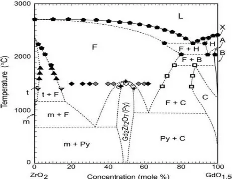
found to be very attractive compared to 7YSZ. Several zirconate pyrochlores have lower thermal conductivity [89, 94, 95] which means they can reduce the temperature at the bulk metal considerably, provided internal cooling is there. Also, their thermal stability is excellent which can be due to the fixed positions of cations in the crystal. Gadolinia- Zirconia phase diagram is shown in Fig. 2.14 where it can be seen that pyrochlore compound gadolinium zirconate (GdZ) has temperature stability up to 1500°C.Improved sinter resistance has been found for EB-PVD pyrochlore TBCs, especially for Gd2Zr2O7 [96] and Sm2Zr2O7 [54, 97-103]. Recently, GdZ has
shown excellent resistance against CMAS and volcanic ash attack [104-106]. Among the widely investigated pyrochlores are the rare-earth zirconates (Ln2Zr2O7), where Ln is any or
combination of La, Gd, Sm, Nd, Eu and Yb [54, 97, 99-103].
Fig. 2.14: Suggested GdO1.5ZrO2 binary phase diagram constructed from a summary of the
24
Among the pyrochlores, La2Zr2O7 (LnZ) seems to have the most promising bulk properties
suitable for ceramic top coat applications. It has a high thermal stability up to 2000°C, a low thermal conductivity of 1.56W/m K and a low sintering tendency [102]. However, it has a relatively low thermal expansion coefficient (CTE) of about 9 x 10⁻⁶ K-1 compared to 7YSZ which has a CTE of 10-11 x 10-6 K-1. This can lead to higher thermal stresses due to the thermal expansion mismatch. In this regard, Gd2Zr2O7 with a relatively higher CTE value of 10.5 x 10⁻⁶
K-1 seems to be advantageous [102].
Fig. 2.15: Cyclic lifetime of Ln-zirconate and Gd- zirconate based single and double layer plasma sprayed TBC systems [101].
Superalloy substrate and bond coats have relatively higher thermal-expansion coefficients (about 15 x 10-6 K-1) and therefore cracks can easily grow due to the stresses which build up in the TBC close to the bond coat during operation [52, 101, 102]. This could be a possible reason for the lower life time of La2Zr2O7 and Gd2Zr2O7 based plasma sprayed TBC systems shown in Fig.
2.15. Incompatibility between pyrochlore and TGO has also been reported which results in the formation of perovskite phase causing a reduction in the TBC lifetime [108]. To overcome these problems, a thin layer of 7YSZ is deposited between the bond coat and pyrochlore compositions. This is called double layer structure and has shown a significantly improved lifetime for many pyrochlore TBC systems as shown in Fig. 2.15. In such a structure, 7YSZ provides a better toughness than pyrochlores close to the bond coat and better adhesion with TGO while the pyrochlore material applied on the top provides low sintering and high thermal stability [102]. These systems based on pyrochlore/YSZ double-layers show excellent high-temperature
25
capability significantly better than the one of YSZ and they are expected to improve the thermal capabilities of gas turbines during application [101].
Some of the pyrochlore compositions are difficult to deposit, especially by EB-PVD technique and some fluctuations in composition have been encountered. For La2Zr2O7, it has been observed
that doping with yttria, in the range of 3-10 wt% reduces the compositional scatter during evaporation [109, 110]. In case of plasma-spraying for La2Zr2O7, loss of La2O3 has already been
stated [111] which leads to an impurity phase of non-stabilized ZrO2 which might be detrimental
for the coating performance.
2.8.3
Perovskites
Perovskite with ABO3 crystal structure have a high temperature stability making them an
attractive candidate for ceramic top coat applications. BaZrO3 and SrZrO3 have been the early
candidate materials for TBC applications. BaZrO3 has a high melting temperature, however, its
relatively poor thermal and chemical stability led to early failure of coatings during thermal cycling tests at 1200°C surface temperature [112]. SrZrO3, on the other hand, has shown better
performance in thermal cycling test at temperatures higher than 1250°C as both lone ceramic top coat and as a double-layer for 7YSZ in a TBC system [113]. However, SrZrO3, at intermediate
temperature of about 730°C undergoes an undesirable phase transformation from orthorhombic to pseudo-tetragonal. It has been observed that such transformation can be suppressed by doping with Gd or Yb, which also improves the thermophysical properties of the coatings at elevated temperatures [114]. CaZrO3 has been the latest material to be considered for TBC applications in
this group. The melting point of this material has been found to be lower than that of 7YSZ, however, it has a promising thermal conductivity of ~ 2 W/m K [115].
Some complex perovskites like Ba (Mg1/3Ta2/3)O3 (BMT) and La(Al1/4Mg1/2T1/4)O3 (LAMT)
have also been tested for ceramic top coat application because of their suitable properties [102, 116, 117]. Despite the promising bulk properties, their toughness is still inferior compared to 7YSZ. In addition, some non-stoichiometric phases form during atmospheric plasma spraying due to the differences in vapour pressure of the component oxides [102, 118, 119]. However, recent study suggested that this problem could be minimized by proper optimization of plasma spray parameters to obtain shorter residence time of the particles in the hot plasma plume [120].
2.9
Sintering of ceramic top coat
Sintering can be defined as a thermal treatment which results in bonding of particles into a coherent, predominantly solid structure via mass transport events which often occur at atomic scale. The process of sintering leads to improved strength and lower system energy [121]. Sintering is driven by reduction in free surface energy and interfacial energy acting over curved surfaces. Two adjacent particles with free surfaces have a higher energy and by undergoing
![Fig. 1.1: Schematic diagram of Rolls Royce Trent 800 engine, which powers the Boeing 777 aircraft [2]](https://thumb-eu.123doks.com/thumbv2/123dokorg/2840694.5131/16.918.174.726.471.831/schematic-diagram-rolls-royce-trent-engine-boeing-aircraft.webp)
![Fig. 1.2: Effect of TBC system on the temperature capabilities of gas turbines [10].](https://thumb-eu.123doks.com/thumbv2/123dokorg/2840694.5131/18.918.158.781.104.523/fig-effect-tbc-temperature-capabilities-gas-turbines.webp)
![Fig. 2.3: FCC phases in Ni-base superalloys, a) γ- Ni matrix and b) γʹ- Ni 3 Al [15]. 2.3 Bond Coat:](https://thumb-eu.123doks.com/thumbv2/123dokorg/2840694.5131/22.918.171.778.236.468/fig-fcc-phases-base-superalloys-matrix-bond-coat.webp)
![Fig. 2.4: Relative oxidation and corrosion resistance of high temperature coating systems [23]](https://thumb-eu.123doks.com/thumbv2/123dokorg/2840694.5131/24.918.238.709.118.591/fig-relative-oxidation-corrosion-resistance-temperature-coating-systems.webp)
![Fig. 2.6: SEM micrograph of a NiCoCrAlY top view after annealing for 4hrs at 1080°C. Different phases identified by EDX are mentioned [47]](https://thumb-eu.123doks.com/thumbv2/123dokorg/2840694.5131/27.918.170.753.251.657/fig-micrograph-nicocraly-annealing-different-phases-identified-mentioned.webp)
![Fig. 2.10: Vapor pressure of different oxides for EB-PVD process [54].](https://thumb-eu.123doks.com/thumbv2/123dokorg/2840694.5131/33.918.178.752.110.525/fig-vapor-pressure-different-oxides-eb-pvd-process.webp)
![Fig. 2.12: Movchan model for the effect of substrate temperature on the microstructure of EB- EB-PVD columns [76]](https://thumb-eu.123doks.com/thumbv2/123dokorg/2840694.5131/36.918.189.726.239.533/fig-movchan-model-effect-substrate-temperature-microstructure-columns.webp)
![Fig. 2.15: Cyclic lifetime of Ln-zirconate and Gd- zirconate based single and double layer plasma sprayed TBC systems [101]](https://thumb-eu.123doks.com/thumbv2/123dokorg/2840694.5131/39.918.127.781.307.671/cyclic-lifetime-zirconate-zirconate-single-double-sprayed-systems.webp)
![Fig. 2.17: A comparison of two identical diffusion bond coats without bond coat, a) after 100 x 1 h thermal cycles at 1150°C and b) after 100 h isothermal heating at 1150°C [153, 161]](https://thumb-eu.123doks.com/thumbv2/123dokorg/2840694.5131/44.918.139.786.313.737/comparison-identical-diffusion-coats-thermal-cycles-isothermal-heating.webp)
