XXX-X-XXXX-XXXX-X/XX/$XX.00 ©20XX IEEE
Design of an Integrated-Photonics RF Beamformer
for Multi-Beam Satellite Synthetic Aperture Radar
Manuel Reza TeCIP Institute Scuola Superiore Sant’Anna
Pisa, Italy [email protected]
Chris Roeloffzen LioniX International Enschede, The Netherlands [email protected] Amin Abbasi Antwerp Space N.V. Antwerp, Belgium [email protected] Ahmad Mohammad LioniX International Enschede, The Netherlands [email protected]
Paul van Dijk LioniX International Enschede, The Netherlands [email protected] Bart Desoete Antwerp Space N.V. Antwerp, Belgium [email protected] Giovanni Serafino TeCIP Institute Scuola Superiore Sant’Anna
Pisa, Italy [email protected] Hakimeh Mohammadhosseini Antwerp Space N.V. Antwerp, Belgium hakimeh.mohammadhosseini@antwerp space.be Paolo Ghelfi PNTLab – CNIT
TeCIP Inst. – Scuola Sup. Sant’Anna Pisa, Italy
Abstract—This paper presents the design and the
performance analysis of a photonics-based beamformer for a spaceborne synthetic aperture radar implementing the scan-on-receive functionality. The considered device is a hybrid photonic integrated circuit composed of actives in InP and passives in TriPleX™, realizing the fast beamforming of three receiver beams out of 12 radio-frequency input signals and providing their simultaneous down-conversion to intermediate frequency. The analysis considers as main performance indicators the gain, the noise figure, and the dynamic range of the photonics-based beamformer, and demonstrates the device compliance to the application requirements and its suitability for satellite missions.
Keywords—Beamforming, photonic integrated circuit, hybrid integration, synthetic aperture radar.
I. INTRODUCTION
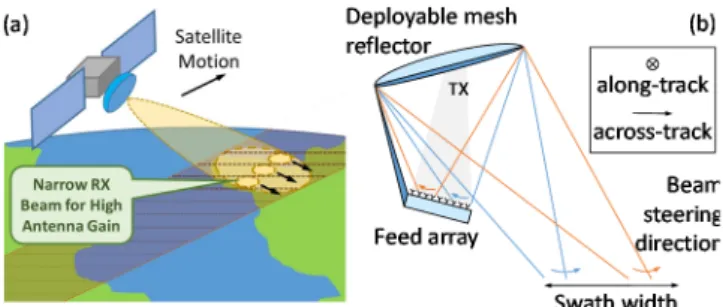
Earth observation from space is fundamental to improve the management of the environment, understand and mitigate the effects of climate change [1], and enhance civil security. Microwave remote sensing, by means of synthetic aperture radars (SARs) from satellites, is a key tool. Recently, an advanced SAR mode has been introduced, called scan-on-receive (SCORE), which operates by illuminating a wide swath and receiving several narrow, high-gain beams that are simultaneously steered to receive the scattered echoes over the whole swath during the satellite flight (Fig. 1-a) [2]. Besides being already studied for several satellites (Sentinel 1 NG, ROSE-L, Tandem-L), the SCORE principle is also crucial for possible future Ka-band SAR missions. A SCORE SAR system can be implemented with a direct radiating array, or alternatively, with a reflector antenna and a feed array. The latter has the advantage to require only few array elements to achieve high beam gain (Fig. 1-b). Currently, only on-board digital beamforming is eligible for SCORE implementation, which requires heavy signal processing by the next-generation space-qualified field programmable gate arrays (FPGAs), leading to large power consumption and dissipation. This would limit the application of the SCORE concept to large spacecrafts only. In order to make the SCORE observation
mode available for smaller SAR missions, a beamforming implementation with reduced size, weight and power consumption (SWaP) is required. Optical beamforming networks (OBFNs) based on photonic integrated circuits (PICs) provide these features intrinsically, due to their broad bandwidth, insensitivity to the electromagnetic interference (EMI), low loss, and transparent link capacity.
Optical beamforming is becoming an interesting technique for different applications where flexible phased array antennas are required. Smart antennas and BFNs are the key concepts for adaptive resource allocation for efficient spectrum usage, and OBFN can bring in continuous and precise delay/phase and amplitude control. Two main OBFN application domains so far have been the fifth generation (5G) of mobile communications [3], [4] and the high-throughput communication satellites with multi-beaming and frequency re-use functionality [5], each with their own specific application requirements.
Moreover, photonics-based radars have been recently demonstrated both using commercial components [6] and implemented as a PIC [7], and are gaining a lot of interest thanks to their broad bandwidth and frequency flexibility. In particular, frequency-agnostic optical components allow to design radars up to Ka-band. Additionally, OBFN can be included in the already demonstrated photonics-based radar architectures.
The recently started SPACEBEAM project, funded by the European Commission, aims precisely at developing an
This work has been supported by the EC through the H2020 project SPACEBEAM (grant no: 870421, www.spacebeam-project.eu).
Fig. 1. (a) Graphical explanation of the scan-on-receive SAR concept. (b) Beamforming based on feed array and reflector antenna, where each beam employs a subset of the feed array elements.
integrated OBFN with down-conversion capability, to enable a low-SWaP SCORE SAR system. This paper presents the concept, architecture, and preliminary design of the PIC-based receiver of the SCORE SAR system to be developed in SPACEBEAM, and highlights the calculated performance with respect to the system requirements, and discusses the future implementation steps of the project.
II. SCHEME OF PRINCIPLE
A. SCORE SAR system architecture and requirements
From the SAR system design point of view, the goal of SPACEBEAM is to have a swath 5 times wider than current spaceborne SAR systems, thus enabling a larger coverage with a 50-km swath width, at the same time guaranteeing a 1.5 m spatial resolution in both along- and across-track directions. This can be achieved using three simultaneous beams generated by an antenna with a deployable reflector and a 12-element feed array to scan the full swath. As a system requirement, each beam, i.e. each receiver output, is constituted by a cluster of K = 5 out of 12 feed array elements (FAEs), which means that some elements are shared between the three beams. The radar signal shall cover a bandwidth of about 390 MHz. Although the OBFN can cover a huge range of frequencies, a SAR in the X-band (namely, at 9.6 GHz) is considered for the implementation of the project demo. In this case, the radio equipment provides an RF local oscillator (LO) at 8.3 GHz, expecting a down-converted signal at an intermediate frequency (IF) of 1.3 GHz. Considering a satellite flying at low Earth orbit (500 to 800 km), and a SAR observing the Earth surface with an incident angle of 20°, the estimated received power at each FAE is roughly in the range from -90 dBm to -58 dBm. Low-noise amplifiers (LNAs) are deployed after the antenna to move the RF power to the range from -54 to -22 dBm. Therefore, the photonics-based beamforming receiver shall ensure a dynamic range > 32 dB. The OBFN is expected to scan on 50 different beaming angles, which requires a beam switching time < 300 ns.
B. Architecture of the SPACEBEAM beamformer
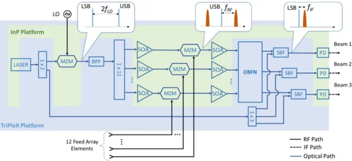
Fig. 2 shows the architecture of the SPACEBEAM beamformer. It is implemented by a PIC based on a hybrid approach, where the opto-electronic and optically active devices (modulators, photodiodes, gain sections) are
developed using the state-of-the-art InP platforms, while the passives (laser resonator, filters, splitters/couplers, and the OBFN) are developed in TriPleX™.
The laser is built interfacing an InP gain section with a resonator in TriPleX: such structure demonstrated to provide an output power > 20 dBm, with a linewidth < 1 kHz [8]. The laser is first split into two paths. One output of the splitter will be used as an optical LO to down-convert the RF signals to IF: at the far end of the PIC, it is further split into 3 copies, which are coupled with the outputs of the OBFN to three photodiodes (PDs). The second path of the laser goes to a Mach-Zehnder modulator (MZM, with a Vπ of 2.3 V and a bandwidth > 36
GHz) where it is modulated by the electrical LO in carrier suppression mode. The modulator output is then filtered to select only one of the sidebands. The band-pass filter (BPF) is implemented with a Mach-Zehnder interferometer (MZI) loaded with optical ring resonators (ORRs) [9], achieving a bandwidth of 4 GHz. The optical sideband is then split into 12 branches by a multi-mode interference (MMI) splitter. On each MMI output, the signal is modulated in a MZM by the received RF signal coming from one FAE. Semiconductor optical amplifiers (SOAs, with a gain of 13 dB and a noise figure NF of 8 dB) before and after the MZMs boost the signal prior to entering the OBFN. The OBFN is conceived as a Blass matrix (described in detail in the next paragraph), which combines the 12 input signals by specific amplitude and phase weights into three outputs, performing the SCORE beamforming. To select one sideband only, and to suppress the out-of-band amplified spontaneous emission (ASE) noise from the SOAs, the three outputs are filtered by the 0.75-GHz bandwidth sideband filters (SBFs, realized as ORRs-loaded MZI filters). Then, they are combined with the three copies of the optical LO, and eventually sent to three PDs (responsivity 0.8 A/W, bandwidth >> 2 GHz), to perform the down-conversion to IF.
Once realized, the InP chips (laser gain section, modulators including amplifiers, and PDs) will be butt-coupled around a larger TriPleX chip including all the passives, to form a single hybrid PIC implementing all the functionalities of the SCORE SAR beamforming receiver. A custom-made packaging will also be developed to guarantee the compliance of the hybrid PIC to a real satellite mission operation.
C. The Blass matrix
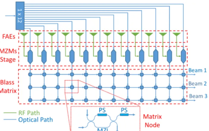
The scheme of a Blass matrix is shown in Fig. 3-a [9]. The Blass matrix consists of horizontal and vertical waveguiding lines (M rows and N columns) that are cross-connected by controlled nodes (Fig. 3-b). A node is composed of a MZI loaded with a phase shifter (PS), and an additional PS on one of the MZI outputs. The MZI works as a tunable coupler, enabling the amplitude control of the signal distributed from the column and propagating along the row to the PD, where all the signals on the same matrix line sum up coherently. The PS after the MZI controls the phase of each signal contribution beating in the PD at the end of the row.
In the SPACEBEAM application, the Blass matrix must accept 12 input signals and combine them into 3 outputs. Therefore, the matrix has 36 nodes. Each node is controlled by two PSs. The Blass matrix therefore requires 72 phase controllers in total. Given the desired beam direction, a set of complex weights (i.e., with amplitude and phase) is calculated for each of the 12 input signals from the array, contributing to each of the 3 outputs. Stepping from the specific SCORE SAR application requirements, an algorithm is developed to map the beamforming complex weights into the required value for each PS [10].
The Blass matrix implementing the OBFN is a passive network, without active components; however, in determining its gain and NF one must consider the combination of different signals on the same output, also taking into account that signals are summed coherently, whereas the noise sums up incoherently. The single output gain GBM and noise figure NFBM of the Blass matrix have been estimated for all the considered pointing directions of the beams, which are between -2.5° and 2.5°. Considering that Ein is the total RF
field impinging on the considered K = 5 FAEs, and Eout,m is
one of the M = 3 outputs, the gain of the m-th Blass matrix output is:
, ( ) = | ,| = √
∑ ( ) | | = 1 ( ) ,
with the ( ) complex weights associated to each matrix node, which vary with the pointing direction θ. In this application, on each matrix row, only 5 out of 12 ( ) have non-zero amplitude. Therefore, it is important noticing that the gain is computed considering an input power equal to 5/12 of
the total power at the antenna. The NF of the m-th output, on the other hand, is expressed as:
, ( ) =
∑ | ( )| |∑ ( )| =
1
, | ( )| .
Applying these formulas, gain and NF have been estimated, and the related plots are reported in Fig. 4, for a single matrix output as an example, showing an average gain of -3 dB, and a NF of 3 dB.
Each pointing direction θ requires a different set of weights, which are obtained by controlling the PSs in the matrix. To control the 72 PSs, a recently proposed technique will be used, exploiting Lead Zirconate Titanate (PZT) piezo-electric actuators deposited on top of the TriPleX waveguides [10]. This solution is much faster than the standard thermal controls, allowing for a 2π phase shift in about 300 ns (instead of hundreds of μs), thus permitting the fast beamforming required by the SPACEBEAM application. Moreover, PZT actuators show almost no power absorption (whereas thermal controls require a large power and produce a significant amount of heat to dissipate). Therefore, PZT is a great candidate for space applications where power consumption and heat dissipation are critical issues.
It is interesting to note that a novel solution for driving the PZT actuators will be tested soon, to further reduce the response time of the phase controls, by overdriving the PZT elements. The aim of this upgrade is to allow the SCORE SAR instrument to increase the scanning resolution, thus reducing the beam width, with a gain in terms of SAR sensitivity.
III. SYSTEM PERFORMANCE ESTIMATION
During the design phase of the SPACEBEAM beamformer, several architectures have been considered (similar to that shown in Fig. 2) by changing the position and the number of the SOAs, and the way the optical LO is generated. The different possible architectures have been evaluated through simulations in VPI Transmission Maker™, considering the gain and the NF as the main metrics. Although the estimated performance is quite similar among the considered architectures, the scheme reported in Fig. 2 exhibited the best performance with an estimated gain of -12 dB and a NF of 30 dB. The gain has been calculated as the difference between one PIC output and the overall input power of 5 FAEs. The NF, on the other hand, is the difference between the signal-to-noise ratio measured at the PIC output and input (where thermal noise at room temperature is assumed). The NF is computed over an integration bandwidth equal to the signal bandwidth, i.e. 390 MHz. The SOAs are assumed to be working in the linear regime. It was observed
Fig. 4. Gain (blue solid line) and NF (red dashed line) of the Blass Matrix vs. the beam pointing direction.
Ga in ( d B ) Noise F igure (dB)
Fig. 3. Schematic depiction of a Blass matrix: each node is composed by a balanced PS-loaded MZI with one output followed by a PS. The FAEs feed the MZMs and, for simplicity, the SOA stages before and after the MZMs have been omitted.
1 x 12 FAEs MZMs Stage PS PS MZI Blass Matrix Matrix Node Beam 1 Beam2 Beam3 RF Path Optical Path
that the NF is significantly reduced by using an ASE-rejecting filter before the PD. In fact, in the beamformer scheme, the ASE-ASE beat noise turns out to be by far the dominant source of noise at IF, with an evident dependence on the optical filter bandwidth. Conversely, the ASE-signal beat noise is not as strong due to the very low signal level, and its effect becomes appreciable only due to the presence of the SBFs.
The estimated value for the gain is high, considering the number of functions performed by the hybrid PIC, compared to other microwave photonics architectures [7]. The value for the NF might sound large, although it is reasonable for a photonics-based down-conversion but, being placed after other RF devices with high gain and lower NF, it does not affect much the NF of the whole SAR receiver.
Besides gain and NF, the spurious-free dynamic range (SFDR) is also estimated by running a two-tone test analysis. The results from the simulation are shown in Fig. 5 where, considering the signal (blue circles) and the 3rd-order
intermodulation product (IMD3, red squares), an output intercept point of the 3rd order (OIP
3) as high as 15.5 dBm is
obtained. The value of the SFDR turns out to be 55 dB for an integration bandwidth of 390 MHz, thus ensuring the dynamic range required by the SCORE SAR application. It is worth noticing that the noise floor (yellow line) is not flat but exhibits a maximum around 15 dBm input power. This is due to the ASE-signal beating summing with the ASE-IMD3 beating. The floor starts increasing when the latter becomes stronger, and it weakens when the two frequency components start saturating. However, it does not roll off as fast as the signal, because the IMD3 power decreases much more slowly. In evaluating the different architectures, the number of SOAs has been also considered, as this impacts the power consumption. The solution considered in Fig. 2 has 24 SOAs, while other schemes are possible with 12 SOAs only, but at the cost of a lower gain. Therefore, we have opted for the most performing solution. In fact, as far as the optical signals are weak (as in this case), the absorption of the SOAs is low, and they consume much lower power than the RF front-end of the SAR, which is expected to contribute for several kW. Still, even with 24 SOAs, the architecture in Fig. 2 has an estimated power consumption < 15 W.
IV. CONCLUSION
This paper has presented the design and performance estimation of an integrated-photonics RF beamformer, aimed at allowing a multi-beam scan-on-receive synthetic aperture radar for satellite Earth observation. The activity is the core of
the SPACEBEAM project and considers the hybrid integration of InP chips including the active components, with a TriPleX chip including the passive components and the Blass matrix implementing the beamforming network. The system simulation estimates a PIC gain of -12 dB and a NF of 30 dB, guaranteeing a dynamic range of 55 dB, well above the specific requirement of the application. Moreover, the control of the Blass matrix implemented through the recently developed PZT piezo-electric actuators allows for a very fast beamforming, permitting the SAR to distinguish between 50 different view angles along a very wide swath of 50 km. After the PIC fabrication, a specific packaging will be developed within the project, to allow the hybrid PIC to reach the space environment compliance.
In the SAR application, the optical beamforming ensures the frequency-agnostic operation with constant performance over the whole interval of possible operating frequencies (up to 40 GHz), with high precision and continuous beam steering. The photonic beamformer, besides controlling the direction of the received beam, also implements a frequency-agnostic photonics-based down-conversion of the received RF signals, so that the beamformed signal at its output can be directly acquired by an ADC, without any further RF down-conversion stage.
The outcome of this activity is expected to open up several new possibilities in other Earth observation applications, showing the potential to become a new standard component for the next spaceborne SARs.
ACKNOWLEDGMENT
The Authors thank all the members of the SPACEBEAM consortium, in particular Dr. Tobias Otto and Dr. Simone Gabrielli from OHB for fruitful discussions on the system requirements.
REFERENCES
[1] Anderson, Katherine, et al. “Earth observation in service of the 2030 Agenda for Sustainable Development,” Geo-spatial Information Science 20.2, pp. 77-96 (2017).
[2] G. Adamiuk, C. Heer, M. Ludwig, “DBF technology development for next generation of ESA C-Band SAR mission,” Proc. of EUSAR 2016:
11th European Conf. on Synthetic Aperture Radar, VDE (2016). [3] J. Epping, et al., "Development of a Broadband Integrated Microwave
Photonic Beamformer for 5G applications," 2018 Photonics in
Switching and Computing (PSC), Limassol, Cyprus, pp. 1-2 (2018).
[4] G. Serafino, et al., “Photonics-Assisted Beamforming for 5G Communications,” IEEE Photonics Technol. Lett. 30 (21), pp. 1826-1829 (2018).
[5] ESA - Application of Satellite On-board Optical Beam Forming (Contract: AO/1-6955/11/NL/NR, https://artes.esa.int/projects/board-optical-beamforming-networks).
[6] P. Ghelfi, et al., “A fully photonics-based coherent radar system,”
Nature 507, pp. 341–345 (2014).
[7] S. Li, et al., “Chip-based photonic radar for high-resolution imaging,” arXiv:1905.12802.
[8] Y. Fan, et al., “Hybrid integrated InP-Si3N4 diode laser with a 40-Hz intrinsic linewidth,” Opt. Express 28 (15), pp. 21713-21728 (2020). [9] L. Zhuang, et al. “Novel ring resonator-based integrated photonic
beamformer for broadband phased array receive antennas—Part II: Experimental prototype,” J. Lightw. Techn. 28 (1), pp. 19-31 (2009). [10] C. Tsokos, et al., “Analysis of a Multibeam Optical Beamforming
Network Based on Blass Matrix Architecture,” J. Lightw. Techn. 36 (16), pp. 3354-3372 (2018).
[11] N. Hosseini, et al., “Stress-optic modulator in TriPleX platform using a piezoelectric lead zirconate titanate (PZT) thin film,” Opt. Express 23 (11), pp. 14018-14026 (2015).