2016
Publication Year
2021-01-25T08:42:51Z
Acceptance in OA@INAF
AOF upgrade for VLT UT4: an 8m class HST from ground
Title
ESPOSITO, Simone; AGAPITO, GUIDO; BONAGLIA, MARCO; BUSONI, LORENZO; Fusco, T.; et al.
Authors 10.1117/12.2234737 DOI http://hdl.handle.net/20.500.12386/29952 Handle PROCEEDINGS OF SPIE Series 9909 Number
PROCEEDINGS OF SPIE
SPIEDigitalLibrary.org/conference-proceedings-of-spieAOF upgrade for VLT UT4: an 8m
class HST from ground
Esposito, S., Agapito, G., Bonaglia, M., Busoni, L., Fusco,
T., et al.
S. Esposito, G. Agapito, M. Bonaglia, L. Busoni, T. Fusco, B. Neichel, P.
Spano, G. Bono, J. Vernet, "AOF upgrade for VLT UT4: an 8m class HST
from ground," Proc. SPIE 9909, Adaptive Optics Systems V, 99093U (27 July
2016); doi: 10.1117/12.2234737
Event: SPIE Astronomical Telescopes + Instrumentation, 2016, Edinburgh,
United Kingdom
AOF upgrade for VLT UT4: an 8m class HST from ground
S. Esposito(1), G. Agapito(1), M. Bonaglia(1), L. Busoni(1), T. Fusco(2) , B. Neichel(2),
P.Spano(1), G. Bono(3), J. Vernet(4)
(1) Osservatorio Astrofisico di Arcetri, INAF, Largo E. Fermi 5, 50125-Firenze, ITALY.
(2) Aix Marseille Université, CNRS, LAM (Laboratoire d’Astrophysique de Marseille) UMR 7326,
13388, Marseille, France
(3) Università di Roma Tor Vergata, Via Orazio Raimondo, 18, 00173 Roma, Italy
(4) European Southern Observatory, Karl-Schwarzschild-Str. 2, 85748 Garching, Germany
ABSTRACT
In this paper we present numerical simulations and an initial design for a visible MCAO system for the VLT-UT4 telescope. The proposed concept takes great advantage of the existing HW developed for the Adaptive Optics Facility (AOF) at the VLT-UT4, in particular the 4x20W Toptica lasers and the adaptive secondary mirror with 1170 actuators. The mentioned units makes the VLT-AOF a unique facility to develop a second generation AO system aiming to provide corrected FoV at short wavelength. In particular the flux provided by the four lasers steerable on sky and the high density of actuators (20cm equivalent on M1) provides the temporal bandwidth and the spatial sampling to push the correction down to the visible wavelengths. In addition to this the request of a reasonable size corrected FoV with uniform performance calls for an MCAO system. For such reason here we propose to complement the AOF with post-focal DMs that together with the VLT DSM can provide a corrected FoV of roughly 20/30 arcsec diameter size. An additional challenge for the system is the provided a large sky coverage. Such condition comes from the efficiency of LO wavefront sensors that use field NGS. The presented simulations give some first results for (a) the achieved performance at visible wavelength 0.4-0.9 um as a function of DMs and tip tilt NGSs characteristics (b) the achieved system sky coverage after. Pushing performance toward visible wavelengths calls for embedded and efficient post-processing methods. Being able to capture short-exposure science images (with the trade-off on noise and overheads), would allow retrieving the ultimate performance by compensating the residual turbulence aberrations left over by the AO system. Considerations about advanced analysis tools that may potentially relax the system constraints are discussed. Finally the paper presents a conceptual arrangement for the opto-mechanics of the considered AO module including the additional DMs and wavefront sensors.
Keywords:
Adaptive Optics in the visible, multi-conjugate AO. VLT adaptive Optics, pyramid sensor
1. INTRODUCTION
Astronomical Adaptive Optics started in the beginning of the 80s aiming at correcting the atmospheric perturbations over a small Field of View (FoV) in the near infrared wavelengths with particular emphasis on K band (2.2 um). The shorter wavelengths were considered impracticable because of (1) the much larger number of degrees of freedom (dof) required and (2) the very small corrected FoV due to natural angular anisoplanatism. In the period 2000-2015 a new generation of AO systems has been designed and successfully tested on sky. It is the case of FLAO[1] the NGS based SCAO system at the LBT telescope and GeMS[2] the LGS based MCAO system of Gemini South. Both systems provided a step forward in ground based high angular resolution imaging providing respectively in H band a SR in excess of 80 and a diffraction limit correct FoV of 80x80 arcseconds. At the same time the VLT Observatory moved forward in AO development with the development of SPHERE [3] and AOF[4]. Such a work leaded in 2014 to the successful operation of SPHERE reaching impressive scientific results. It is important to notice that both FLAO and SPHERE did perform AO correction at visible wavelength achieving SR like 40% at 650nm. At the same time progress of the AOF development will make available, at VLT UT4 in a short time, a 1172 actuators deformable secondary and 4 LGS beacons the last ones successfully tested in 2016. The present paper proposes to set up an MCAO system working at visible wavelength by taking advantage of the facility already existing at the UT4. This proposal would represent an ideal replacement for HST,
and cover a parameter space that would not be covered by any of the ELTs first light instruments. Briefly the proposed
system delivers at 650nm, in our simulations, diffraction limited FoV (PSF FWHM of 15mas) over a field of 30 arcsec Adaptive Optics Systems V, edited by Enrico Marchetti, Laird M. Close, Jean-Pierre Véran, Proc. of SPIE Vol. 9909, 99093U
© 2016 SPIE · CCC code: 0277-786X/16/$18 · doi: 10.1117/12.2234737
Proc. of SPIE Vol. 9909 99093U-1
Downloaded From: https://www.spiedigitallibrary.org/conference-proceedings-of-spie on 25 Jan 2021 Terms of Use: https://www.spiedigitallibrary.org/terms-of-use
diameter with a uniform SR and an EE50 of 20% and 200mas respectively. The proposed system design requires to add to the existing AOF capabilities a small deformable mirror conjugate to 8km altitude (2 inch size) and a WFS module.
2. MCAO INSTRUMENTATION AND SCIENCE GOAL
2.1 Potential instrumentation
Potential science cases that would greatly benefit from medium-size diffraction limited images (or spectra) in the visible go from the solar system to distant galaxies. Of course, it all depends on the kind of instrumentation that one would envision to couple with the AO system. One option that would be appealing is to combine both spectroscopy and imaging capability, paving the focal plane with Micro-mirrors. This would be somehow similar to the recent GMOX instrument proposed for Gemini (see: http://www.gemini.edu/sciops/instruments/gifs/GMOX_Final_Report_Public.pdf), or the BATMAN instrument currently built for the TNG [5]. With such instrumentation, we could envision to cover the full wavelength range, from the blue (e.g. B-band) to the NIR (e.g. H or K-band), by splitting the light into three different channels, each covering a specific wavelength range. For each channel, the focal plane is then paved with micro mirrors, sending the light either toward and imaging camera, or toward a spectrograph. This allows for Multi-Object Spectroscopy (MOS), but also represents a very flexible and efficient instrument, as the slit sizes and positions can be adjusted by a simple button click. For instance, we could consider to optimize the slit size depending on the seeing conditions, and the MCAO correction level. The current technology offers matrices of micro-mirrors of 4k x 4k, hence slits as small as 10mas could be implemented for the visible channel. Such an instrument could be equivalent to the VLT X-Shooter, but providing MOS and high-angular resolution capabilities. Science applications for such an instrument are enormous, resolving hundreds of galaxies through the cosmic time, dissecting star forming regions in nearby galaxies, resolving stellar populations in very dense environment, providing exquisite details on nearby solar system objects. Pushing AO performance toward visible is challenging, and the expected performance will be highly dependent on the environment conditions (e.g. seeing, vibrations, etc…). On the other hand, pushing toward visible wavelengths opens the path to visible science detectors that have a lot of benefits (better QE, lower read noise). In particular, if the read-out noise is small enough one can imagine reading them fast (e.g. 5 frame per second for a 4k x 4k detector with less than 1é RON [6]), and use advanced post-processing methods in order to compensate for the partial AO correction. This will ensure to get the best angular resolution, and signal to noise, out of this challenging instrument.
2.2 Detailing a science case
Among the different science cases for a visible MCAO at VLT, we give further details on a specific one that would greatly benefit from such an instrument: Globular Clusters (GCs) and White Dwarf (WD).
The superb image quality of ACS and WFC3 at HST provided a unique opportunity to investigate the WD cooling sequences in a good sample of nearby stellar systems [16] [17] [18]. The same applies for wide field imagers available at the 8--10m class telescopes [19]. However, we still lack accurate elemental abundances of WDs in GCs. The reason is two-fold:
1. they are located in crowded fields and very high spatial resolution is required to limit light contamination from neighboring stars;
2. they are faint targets (V< 21 mag), which means that they have only been observed in low-resolution with ground-based facilities.
The imager and spectrograph we plan to develop is going to play a crucial role concerning the detection and the characterization of WDs in nearby stellar systems (Bulge, Thin Disk, Halo). WDs in the bright portion of their cooling sequence attain effective temperatures that are earlier than F and G spectral types. This means that they are significantly brighter in blue/visual bands than in the NIR bands. An imager with a field of view of 1 arcmin and a pixel scale of 0.005 could then provide an accurate optical color-magnitude diagrams of both GCs and in relatively low-reddening regions of the Galactic Bulge. The latter region has only been marginally investigated by HST [20]. In this context the opportunity to collect optical (BVI) images also means to take full advantage of the optical images that have already been collected by HST to improve the precision of the astrometry, and in turn the separation between cluster and field stars. Note that this approach also applies to stellar systems in nearby dwarf galaxies (Magellanic Clouds, Sagittarius).
The spectroscopic mode will allow to constrain the evolutionary status of the WDs (He vs CO core, DA [H in the atmosphere] vs DB [He in the atmosphere]) and their evolutionary channel. Futhermore, the opportunity to discriminate
Proc. of SPIE Vol. 9909 99093U-2
Downloaded From: https://www.spiedigitallibrary.org/conference-proceedings-of-spie on 25 Jan 2021 Terms of Use: https://www.spiedigitallibrary.org/terms-of-use
500 400 m 300 200 100 0 LGS-FoV = 60" - 3DM - 4LGS LGS-FoV = 60" - 3DM - 6 LGS LGS-FoV = 60" - 3DM - 9 LGS 10 20
FoV position ( aresec) 30
40
between He-enhanced and hot helium flashers scenario [21]. The latter working hypothesis predicts that he-enhaced WDs are also C and N enhanced. This issue is far from being an academic issue, since the He-enahnced scenario has been invoked to take account of the multiple populations in globulars.
3. SYSTEM PERFORMANCE SIMULATIONS
To evaluate the performance of the considered VIS MCAO system we did two steps. In the first one we did study the system configurations in terms of main parameters like # of DMs, # of LGS, Corrected FoV size etc. With the identified set of main parameters we did some E2E simulations to provide the system performance.
3.1 Exploring the parameter space
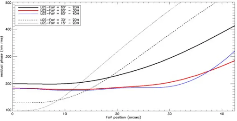
The initial simulations have been aimed to evaluate the effect of # of DMs, # of LGS and size of FoV. These simulations have been done with analytical code order to explore efficiently the parameter space. Figure 1 reports the results. We see that the 60 arcsec FoV even with 3 or 4 DM is somewhat limited in performance to an rms of about 180nm that provides low performance in the visible with a peak SR of 5% at 650nm. The main limitation here is due to the tomographic process and the use of only 4 LGS. Increasing LGS number (and especially adding a central one) will significantly reduce the tomographic error and thus improve the final performance. The 30 arcsec FoV with a 130nm rms over 20 arcsec diameter and extending to roughly 30 arcsec seems a good compromise between wavelength and PSF quality. Such trade off could be revised depending on the scientific requirements put on the achieved PSFs.
Figure 1. Analytical simulations of residual phase vs. FoV position for 2,3 and 4 DMs and 15, 30 and 60 arcsec FoV.
Figure 2. Analytical simulations of residual error for a 60 arcsec FoV vs. number of guide star.
As an additional point we explored the use of more than 4 lasers. Again Figure 2 shows that a 3 DMs system is limited by the # of available LGS, 4 in the AOF case.
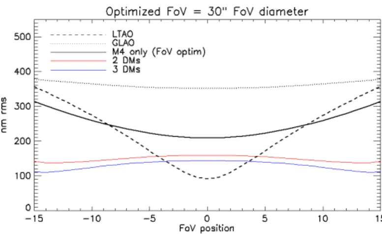
Finally we run the code in the 30 arcsec case and compare LTAO, GLAO and MCAO.
Proc. of SPIE Vol. 9909 99093U-3
Downloaded From: https://www.spiedigitallibrary.org/conference-proceedings-of-spie on 25 Jan 2021 Terms of Use: https://www.spiedigitallibrary.org/terms-of-use
LTAO
GLAO
M4 only (FoV optim)
2 OMs 3 OMs
Optimized FoV = 30" FoV diameter
500 400 m E 300 E c 200 100 0 -15 -10 -5 0 5 10 15 FoV position
In Figure 3 we see that the performance of the MCAO system is a good trade off between GLAO and LTAO providing a significant correction with about 130nm rms over the full field. On such basis we decided to do an E2E simulation study of the MCAO system having 2DMs and a corrected FoV of 30arsec as detailed above. Obviously this is a first attempt, and depending on how the science top level requirements evolve (e.g. FoV, wavelength, EE), we will revise the
simulations
.
Figure 3. A comparison between GLAO, LTAO and MCAO with 2 and 3 DMs in the considered case of 4 reference guide stars.
3.2 MCAO E2E simulations
In this section we described the results obtained by end-to-end simulations. These simulations were performed using the software tool PASSATA (PyrAmid Simulator Software for Adaptive OpTics Arcetri[7]). As discussed above we selected as configuration 4LGSs, an asterism of 30” of diameter and 2DMs, which, as it is said before, is a good compromise for a visible MCAO. The parameters used by the simulation are described in Table 1.
Note that for each LGS a single conical propagation is made and the 3D object elongation is added by means of a convolution with 2D kernels on the detector plane. These 2D kernels are computed considering the launcher, the sodium profile and the WFS geometry.
Table 1. Parameters used by the simulations.
Parameter
Value
Telescope:
Entrance Pupil Diameter
Central Obscuration ratio
D
ε
8.118 m
15.9 %
Atmospheric conditions:
Seeing
Outer scale
No. layers
L
00.66 arcsec (0.71 with zenith angle 30°)
25m
10[8]
Transmission:
NGS
LGS
ܶ
ܶ
0.344
0.400
Proc. of SPIE Vol. 9909 99093U-4
Downloaded From: https://www.spiedigitallibrary.org/conference-proceedings-of-spie on 25 Jan 2021 Terms of Use: https://www.spiedigitallibrary.org/terms-of-use
Parameter
Value
Deformable mirror #1:
Conjugated height
1170 Influence Functions (IFs) obtained
from the FEA model of the DSM
0m
Deformable mirror #2:
Conjugated height
250
8500m
KL
modes
WFS Camera detector:
RON
σ
R4 e
-/pix/frame
LGS WFS:
Number
Type
No. sub-aperture
FoV
Central Wavelength
Pixel per sub-aperture
λ
wf s4
Shack Hartmann
40x40
5.0x5.0 arcsec
589nm
6x6
LO NGS WFS:
Type
No. sub-aperture
FoV
Central Wavelength
Bandwidth
Pixel per sub-aperture
λ
wf sShack Hartmann
2x2
2.5x2.5 arcsec
768nm
600 – 1000nm
16x16
AO RTC:
Max frame frequency
Slope computer algorithm
Control
Reconstruction matrix
Temporal controller
Total time delay
1 kHz
Centre of Gravity (CoG).
Modal control with static modal gains
MMSE[10][11][12]
Simple integrator (gain=0.5)
3ms
LGS specific information:
LGS spot FWHM
Laser launcher position
Sodium profile
0.8 on-sky arcsec
5.49m from telescope axis
“Single Peak” sodium profile (from [9] with
UTC = 20080717 – 06_40_56)
4. E2E SIMULATION RESULTS
In this section we present the results given by E2E simulations. These simulations are 2s long and we compute the long exposure on-axis PSFs and PSFs at 5, 10 and 15 arcsec distance from the axis. For each long exposure PSF we compute the SR, the FWHM and the Encircled Energy to evaluate the performance.
Firstly we report the results given by the 30 arcsec asterism configuration: performance at wavelengths between 500 and 850nm are summarized in Figure 4. D.L. performance of a 2.4m diameter telescope are shown in the plots as dashed lines and can be use as comparison with HST. It can be seen that the performance in the corrected FoV are uniform, that the SR@850nm is greater than 30% everywhere, that the FWHM values are very similar to the D.L. one and that even at 500nm the diameter of 50% of the energy is a factor 2 of the seeing limited one (about 650mas).
Proc. of SPIE Vol. 9909 99093U-5
Downloaded From: https://www.spiedigitallibrary.org/conference-proceedings-of-spie on 25 Jan 2021 Terms of Use: https://www.spiedigitallibrary.org/terms-of-use
0.2 -_
2
ast. diam. 3
6 8
distance [aresFec]10
14 2 6 dista 100 200 ra FWHM [mas] 650nm asr,. mam. 00"+ asr,. mam. 15"p 8 10 12 ance [aresec] ast. diem. 30" ast. diem. 15" 300 40 Ldius [mas] ast. diam. 30 onm onm onm onm 6 8 distance [aresec IA 10 500 10 12 14 ,] 2 6 diste ast. tliam. 30" ast. tliam. 15" 10 o
diameter (EEC50 %) [mas]
650nm ast. diem. 30"+ ast. mam. 15,3 B ance [aresec] 100 1dius [mas] ast. diam. 30' 6 8 distance [aresee] IA 14 Then we pres • A c seen Ene • A c con • A c prov Figure 4. Dashed l Figure 5. Energy a
sent some com omparison be n in Figure 5 ergy on axis, b comparison be nfiguration is a comparison be ve that the two
. Visible MCA lines correspon . Comparison at 50% diamet mparison: tween the 30 5 the smaller but worst perfo etween three d a 2nd DM at 85 etween the M o WFSs have AO performan nd to D.L. PS between 15 a ter. Bottom: P arcsec asterism asterism give formance near different 2nd D 500m. MCAO based same behavio nce at 500, 650 SF from a 2.4m and 30 arcsec a SF profiles (le m configurati es a less unif the border of DM height con on SH WFSs or. 0, 750 and 85 m telescope. asterism confi eft) and Encir
on and the 15 form correctio f the FoV. nfigurations w s and Pyramid 0nm with 4L igurations at 6 rcled energy p arcsec asteris on with highe where we see d WFSs. The GSs, an asteri 650nm. Top: S profiles (right) sm configurat er SR and be from Figure 6 results show ism of 30" and SR (left) and E ). ion. As can be etter Encircled 6 that the bes wn in Figure 7 d 2DMs. Encircled e d st 7
Proc. of SPIE Vol. 9909 99093U-6
Downloaded From: https://www.spiedigitallibrary.org/conference-proceedings-of-spie on 25 Jan 2021 Terms of Use: https://www.spiedigitallibrary.org/terms-of-use
0.5 0.a 0.3 G 0.2 0 00 2 ä 0.3 0.2 0.1 00 2 650nm est. siam. 30' est. siam. 15' est. siam. 30' est siam. 15' ast. siam. 30" ast. siam. 15" 6 8 distance[aresf 650nm asi. c asa. m: 6 8 distance [aresec " 50142=5000m i F " 50142=5000m0 0 " 50M2=6500m i F " IMAM6500m0 10M2=12000mi F nnm2=12000m0 O 10 12 14 c] 12 14 0.5 0.a 0.3 G 0.2 0 00 2
diameter (EEC50 %) [mas]
o
i
650nm est diem. 30" I est diem. 15" I est diem. 30" I est diem. 15" I est. diem. 30" R est diem. 15" R 6 distance[aresec 650nm distance [arcs 515142=5000mi F h0M2=500065* O 50142=650065i F IMAM6500m* O OM2=1200065 ; F Om2=1200065 0 O 12 14 t. diam. 30 SHi F diam. 30 P9r. 0 10 12 14 see] FWHM [mas] OO
650nm cl am. 30" 51412=500050 cl am. 15" 51412=500050 tliam. 30" 51412=050050 (Ham. 15" 51412=050050 (Ham. 30" 51412=12000m (Ham. 15" 51412=12000m r r r r 8 r r distance [aresec] 650nm t. aiam. 30" SH t. aiam. 30" Pyr. 6 8 distance[aresec 12 14 14 Figure 6. Figure 7. right: dia system w Here we pres we describe mirror are pro The proposed identical off-a distance atmo proposed lay Because of th and it generat The plane co pupil as show A flat dichro transmits a na direction tow The variable plane a 4 fac MCAO bench px/subap and WFSs). A 75 focal length ( . Performance . Performance ameter of 50% with SH WFSs5.
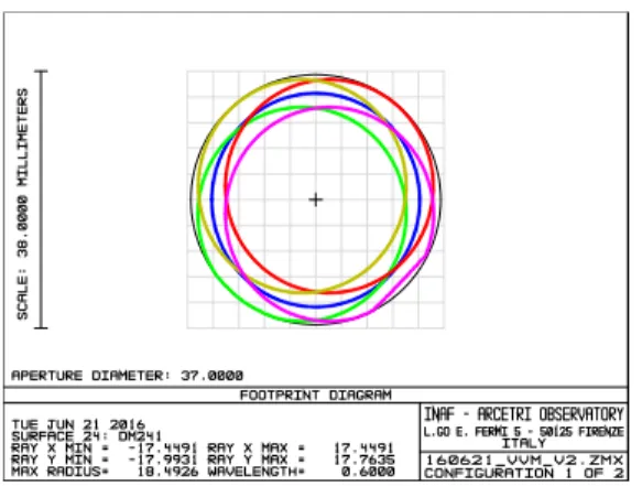
sent a possible the WFS mo ovided by the d MCAO relay axis parabolas ospheric layer yout, very sim he symmetric tes diffraction onjugated to 8 wn in Figure 9 oic beamsplitt arrow bandwi wards the botto LGS distance es reflective p h. The 4 LGS d a 240x240 p 5 mm collima (F/28) corresp e at 650nm in e comparison o % of Encircleds and green lin
A POSSIB
e opto-mechan odule and theAOF already y adopts a 1-t s. A 400 mm r onto the pos milar to other layout of the n limited spots 8.5 km distanc . ter is placed idth centered o om of the MCA e is compensa prism separate S WFS have b pixel detector ator produces ponding to a 5 function of th
of an MCAO d Energy@650 nes correspond
BLE MCAO
nical layout f additional D . to-1 scheme w focal length p st-focal DM. T MCAO relay e 2 parabolas, s over the full ce is compati in the conve on 589 nm wh AO relay benc ated with a re es the 4 LGS been sketched of 24 um pitc the 5.76 mm ” FoV on-sky he 2nd DM hei system with 4 0nm, bottom: F ds to a systemO OPTO-M
for the above m DM because thwhere the Nas parabola collim
The second p ys like the TM
, the relay per FoV served b ible with the u
rgent beam t hile it reflects ch to provide eflective trom beams and it d considering ch (compatible m diameter pup y. Figure 10 al ight. 4 LGSs and 2D FWHM@650 m with Pyramid
MECHANIC
mentioned 2D he LGS refer smyth focus o mates the tele parabola repro MT NFIRAO rfectly compe by MCAO (see use of an Alp o split the ar the remaining a gravity inva mbone as show t directs the li a Shack-Hart e with the E2V pil on the len lso shows a Z DMs. Top-left 0nm. Red lines d WFSs.CAL LAYO
DMs 30 arcsec ence beacons of the VLT is scope beam a oduces the F/1 OS system [13 ensates for thee Figure 8). pao DM241 h rtificial from g visible and ariant focus fo wn in Figure
ight into the 4 tmann layout V CCD220 th nslet array of emax simulat ft: SR@650nm s correspond t
OUT
c FoV system s and the groure-imaged aft and it conjuga 13.6 beam of 3], is sketched e off-axis com having a 37.5 natural sourc infrared light or the instrume 10. Close to t 4 LGS WFS t with 40x40 su hat will be use 0.144 mm pit tion of the LG m, top-to a m. In particular und conjugate ter a couple o ates the 8.5 km the VLT. The d in Figure 8 ma componen mm diameter ces. The optic in the vertica ent.
the LGS foca that lay on the
ubapertures, 6 ed in the AOF tch and 4 mm GS spots where r e f m e 8. nt r c al al e 6 F m e
Proc. of SPIE Vol. 9909 99093U-7
Downloaded From: https://www.spiedigitallibrary.org/conference-proceedings-of-spie on 25 Jan 2021 Terms of Use: https://www.spiedigitallibrary.org/terms-of-use
.J
3D LAYOUT
TUE TUN 21 2016 INAF - ARCETRI OBSERVATORY
L.G0 E. FERII 5 - 50125 FIRENZE ITRLY
160621_VVM_ V 1.2MX CONFIGURATION 1OF 2
oer: D.ma. 0.0D1e CEG
DIB: 8.8D,
[ET: O.EB3J. D.dtle OD,
DAI -5.470,.5.E64BB
MINCE IMT R
E®: -0.Ql#\ O.dCB[EG
DH.6.770, 4,862 MI
CE7: BIGI, -BALM á6
INY. d.74B, 6.696 MI ON: -6.6638. -6.6638 EEC Dfl. 5.740, 5.695111 D.4DDD 1.0000 1.100D SPOT DIAGRAM 1LE l011 21 FIELD RHS RADDIS: GEO 18:01115 SCFLE 00R 2816 :
WITS ARE pn. AIRY RAOD.IS:18.3 I.
l 2 3 4 5
0.566 ].154 ].821 1.021 1.154
0.893 2.315 1.776 1.776 2.315
4D REFERENCE CHIEF RAY
INAF - ARCETRI OBSERVATORY L.GD E. FERFIC ITRLY5 - 50125 FIRENZE 160621_VVM_V1.2MX CONFIGLIRFITION 2 OF 2 I
I
8,6963 , 6267 ,5571 8,4874 0.4178 0,3482 0,2785 0.2089 .1393 0.0696 0.0000 IMAGE DIAGRAM TUE SUN 21 2016IMAGE WIDTH = 6.1440 MILLIMETERS, 256 X 256 PIXELS FIELD POSITION: 8 0808, 0.0000 DEG
PERCENT EFFICIENCY: 100,000x,1,000E+000 WATTS SURFACE', 58. UNITS ARE WATTS PER MILLIMETERS SQUARED.
INAF - ARCETRI OBSERVATORY L.GO E. FERMI 5 - 58125 FIRENZE
ITALY
160621VVM_V6 ,ZMX
CDNFICURRTIDN 4 OF 4
an object with Gaussian profile equivalent to 1” FWHM placed at 90 km distance from the telescope has been imaged through the whole LGS optical path onto the detector image plane.
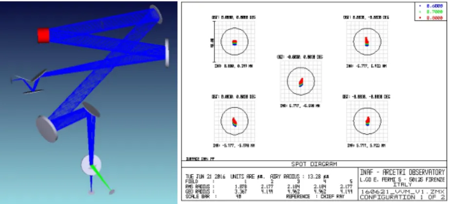
Figure 8. Left: optical layout of the proposed MCAO relay. Right: spot quality obtainable on a 30x30" FoV on the focal plane re-imaged by the relay.
Figure 9. Arrangement of the optical footprints for a 30x30 arcsec FoV on the plane conjugated to 8.5 km distance.
Figure 10. Left: 3D model of the LGS light path in the MCAO relay. The sketch highlights the 4 LGS WFS arrangement. Right: simulation of the 40x40 SH spot grid generated by a Gaussian object of 1 arcsec FWHM placed at 90 km distance.
Proc. of SPIE Vol. 9909 99093U-8
Downloaded From: https://www.spiedigitallibrary.org/conference-proceedings-of-spie on 25 Jan 2021 Terms of Use: https://www.spiedigitallibrary.org/terms-of-use
0.055). 0.SID1 0K
C87: 0.09B. O.dli1 C6:
[87 -0.0CIJ. A.A. G&
0A.6.T7, 4.641 MI DA. -5.477, S.S9858 DIME IAT R CAD: S.SQS. -S.SQD CAS DA: .6.017, 6.9E2 Mi C61: -8.86#0. -8.8638 GEC nEi. 5.7P7, 5.922 111 0.EC00 SPOT DIRGRRM 7LE TUN 21 2016 FIELO MIS WOWS : GBO 0Po0I5: SCf9_E BRR:
WETS Rfd=pn. EORY RNGOJS:13.2BD11
l 2 3 4 5
].B7B 2.177 2.184 2.184 2.177
3.367 4.144 4.962 4.!K2 4.144
4B REFERENCE :CHIEF RRY
INAF - ARCETRI OBSERVATORY L.GO E. FERMII5
-TRLY50125 FIRENZE
160621_VVM_V1.21,1X
CONFIGLJRFITIDN 1OF 2
To keep fixed the LGS asterism on the MCAO relay and to stabilize the ground-conjugate actuators pattern on the LGS WFS a derotator has been inserted in the optical path, close to the VLT Nasmyth focus. This will allow to compensate for the elevation movement of the telescope. To avoid chromatic effects in the relay the derotator has been sketched as a K-mirorr. In this scheme the natural sources must be derotated to compensate also for the azimuthal movement of the telescope. For this purpose we foresee to insert a mechanical rotator below the MCAO bench where the NGS WFS and instrument will be interfaced.
Figure 11 shows a possible arrangement for the natural guide star pickoff: a dichroic beamsplitter separates the infrared light (green path) used for wavefront sensing and the visible scientific light (blue path). This approach will maximize the sky coverage of the NGS WFS while saving all the visible radiation for science.
Being close to the focal plane (~100mm distance) the dichroic is 50mm in diameter and 3mm thick, wedged by 0.16° and co-rotates with the instrument. Figure 11 shows the optical quality obtained on the instrument focal plane at visible wavelengths.
Figure 11. Left: 3D model of the natural sources optical path up to the instrument (blue) and NGS WFS (green) focal planes. Right: spot pattern generated by a 30x30" FoV on the istrument focal plane.
The NGS WFS is a 5x5 subapertures Shack-Hartmann working at infrared wavelengths. We considered 50x50 px/subaperture at about the Nyquist sampling at J band corresponding to a ~3” FoV. A 75 mm collimator has been used to image a 6 mm pupil on the lenslet array having 50 mm focal length and 1.2 mm pitch. This sensor will also act as slow truth sensor to de-trend the low-order modes measured from the LGS WFS that could be affected by the sodium layer variability.
5.1 Implementation with Pyramid WFS
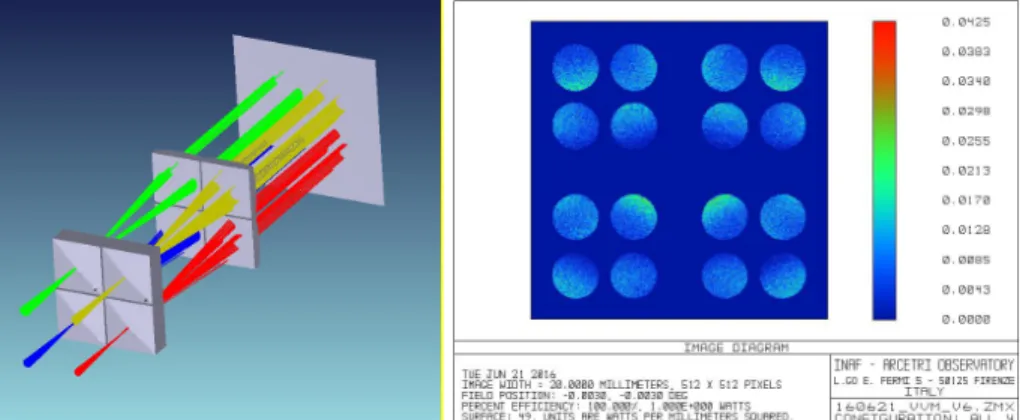
A valid alternative to implement both the NGS and LGS WFS for a MCAO system is to use Pyramid WFS. At infrared wavelengths the higher correction obtainable through the AO system will allow the Pyramid WFS to work with a diffraction limited source maximizing the NGS WFS sensitivity. In the LGS case the possibility to make use of the Pyramid WFS has been demonstrated by numerical studies [15]. In the proposed layout the 4 LGS lay on a square asterism having 30” side. On the LGS focal plane this corresponds to a 15 mm separation between the 4 sources, allowing to place side by side 4 single pyramids with square bases of 10 mm side. The same approach can be used to flank 4 camera lenses that allow to generate the pupil images seen by each LGS. Due to the F/13.6 beam coming from the MCAO relay the interdistances between the 4 groups of pupils will be too large to be imaged directly on a single detector, hence a >2x beam compressor will be need in between.
Proc. of SPIE Vol. 9909 99093U-9
Downloaded From: https://www.spiedigitallibrary.org/conference-proceedings-of-spie on 25 Jan 2021 Terms of Use: https://www.spiedigitallibrary.org/terms-of-use
, 0383 0,0340 0.0255 0.0213 0.01. 0.0043 .0000 IMRGE DIRGRRM TUE IDN 21 2016
IMRGE WIDTH = 30.0000 MILLIMETERS, 512 X 512 PIXELS FIELD POSITION: -0.0030, -0.0030 0EG PERCENT EFFICIEICY 100.00011. LIME WRITS SURFACE: 49. DNIIS PRE WRITS PER MILLIMETERS SCARRED.
INFO - RRCETRI OBSERVATORY
L GO EFER11pR5 aas FIRENZE
16062L_VVM_V 6,ZMX
Figure 12. Left: 3D model of the 4 LGS arrangement on the relay focal plane. The 4 LGS WFS are designed as Pyramid WFS. Right: simulated image of the 4x4 pupils generated on the LGS Pyramid WFS image plane.
6. CONCLUSIONS & FUTURE WORK
In this paper we proposed the implementation of a Multi Conjugate AO system at the VLT UT4. Such a system will take advantage of all the HW already deployed via the VLT Adaptive Optics Facility AOF. In particular the proposed system will use the DSM with 1172 actuators providing correction down to visible range and the existing 4 LGS referenc beacon providing the required system sky coverage. A first round of numerical simulations shows that such a system using a second additional DM conjugated to 8km altitude will provide SR over 20% at 650 nm with uniformly distributed over a FoV of 30 arcsec diameter. Same performance has been achieved by using 4 PWFS as LGS wavefront sensors. A draft optomechanical design of the required AO module has been done and shown to be feasible allocating an overall volume of approx. 1mx1m. In the case of PWFS implementation the 4 LGS WFS could fit all in a single CCD220 simplifying the design. We plan to further investigate the provided first design to come up with a completed conceptual design in the next months.
REFERENCES
[1] Esposito, S., Riccardi, A., Pinna, E., Puglisi, A., Quirós-Pacheco, F., Arcidiacono, C., Xompero, M., Briguglio, R., Agapito, G., Busoni, L., Fini, L., Argomedo, J., Gherardi, A., Brusa, G., Miller, D., Guerra, J. C., Stefanini, P. and Salinari, P., “Large Binocular Telescope Adaptive Optics System: new achievements and perspectives in adaptive optics,” Proc. SPIE 8149 (2011).
[2] Rigaut, F., Neichel B., Boccas, M., d'Orgeville, C. et al., “GeMS: first on-sky results,” Proc. SPIE 8447, Adaptive Optics Systems III, 84470I (2012).
[3] T. Fusco, J.-F. Sauvage, C. Petit, A. Costille, K. Dohlen, D. Mouillet, J-L Beuzit M. Kasper, M. Suarez, C. Soenke, E. Fedrigo, M. Downing, P. Baudoz, A. Sevin, D. Perret, A. Baruffolo, B. Salasnich, P. Puget, F. Feautrier, S. Rochat, T. Moulin , A. Deboulbé, E. Hugot, A. Vigan, D. Mawet, J. Girard, N. Hubin ”Final performance and lesson-learned of SAXO, the VLT-SPHERE extreme AO: from early design to on-sky results”, Proc. SPIE 9148, (2014).
[4] Hackenberg, W., Bonaccini Calia, D., Buzzoni, B., Comin, M., Dupuy, C., Gago, F., Guidolin, I. M., Guzman, R., Holzloehner, R., Kern, L., Kirchbauer, J., Lewis, S., Lizon, J., McLay, S., Pfrommer, T., Quattri, M., Quentin, J. and Ridings, R., “Assembly and test results of the AOF laser guide star units at ESO,” Proc. SPIE 9148 (2014).
[5] Zamkotsian F. et al., “Building BATMAN: a new generation spectro-imager on TNG telescope”, Proc. SPIE, 9908-344 (2016) this conference.
[6] Gach J.L. et al. “Development of a 4kx4k frame transfer electron multiplying CCD for scientific applications”, Proc. SPIE, 9154, id. 91540A 7 pp. (2014)
[7] Agapito, G., Puglisi, A. and Esposito, S., “PASSATA: object oriented numerical simulation software for adaptive optics,” Proc. SPIE 9909, in these proceedings (2016).
Proc. of SPIE Vol. 9909 99093U-10
Downloaded From: https://www.spiedigitallibrary.org/conference-proceedings-of-spie on 25 Jan 2021 Terms of Use: https://www.spiedigitallibrary.org/terms-of-use
[8] “Input parameters for the AO facility simulations: Design of the high order LGS WFS”, VLT-SPE-ESO-11250-4110 (2010).
[9] Pfrommer, T. and Hickson, P., “High resolution mesospheric sodium properties for adaptive optics applications,” A&A 565, A102 (2014).
[10] Johnston, D. C. and Welsh, B. M., “Analysis of multiconjugate adaptive optics,” J. Opt. Soc. Am. A, 11(1), 394-408 (1994).
[11] Fusco, T., Conan, J. M., Michau, V., Rousset, G. and Assemat, F. “Multi-conjugate adaptive optics: Comparison of phase reconstruction approaches for large field of view,” Proc. SPIE 4167, 168–179 (2000). [12] Neichel, B., Rigaut, F., Bec, M. and Garcia-Rissmann, A., “Reconstruction Strategies for GeMS,” 1st AO4ELT
conference, 02010 (2010).
[13] Glen Herriot ; David Andersen ; Jenny Atwood ; Corinne Boyer ; Peter Byrnes ; Kris Caputa ; Brent Ellerbroek ; Luc Gilles ; Alexis Hill ; Zoran Ljusic ; John Pazder ; Matthias Rosensteiner ; Malcolm Smith ; Paolo Spano ; Kei Szeto ; Jean-Pierre Véran ; Ivan Wevers ; Lianqi Wang ; Robert Wooff; NFIRAOS: first facility AO system for the Thirty Meter Telescope. Proc. SPIE 9148, Adaptive Optics Systems IV, 914810 (July 21, 2014); doi:10.1117/12.2055525.
[14] F. Quiros-Pacheco, E. Pinna, A. Puglisi, L. Busoni, G. Agapito, S. Rabien, S. Esposito, “Pyramid wavefront sensor performance with laser guide stars”, in AO4ELT3 conference, 2013
[15] S. Esposito, G. Agapito, C. Giordano, A. Puglisi, E. Pinna, C. Blain, in publication, this proceedings.
[16] Monelli et al., “The Discovery of More than 2000 White Dwarfs in the Globular Cluster ω Centauri,” ApJ, 621, L117 (2005).
[17] Calamida et al., “On the White Dwarf Cooling Sequence of the Globular Cluster ω Centauri,” ApJ, 673, L29 (2008).
[18] Hansen et al., “Constraining Neutrino Cooling Using the Hot White Dwarf Luminosity Function in the Globular Cluster 47 Tucanae,” ApJ, 809, 141 (2005).
[19] von Hippel et al., “From Young and Hot to Old and Cold: Comparing White Dwarf Cooling Theory to Main-Sequence Stellar Evolution in Open Clusters,” ApJ, 622, 565 (2005).
[20] Calamida et al., “New Insights on the Galactic Bulge Initial Mass Function,” ApJ, 810, 8 (2015).
[21] Latour et al., “A Helium-Carbon Correlation on the Extreme Horizontal Branch in ω Centauri,” ApJ, 795, 106 (2014).
Proc. of SPIE Vol. 9909 99093U-11
Downloaded From: https://www.spiedigitallibrary.org/conference-proceedings-of-spie on 25 Jan 2021 Terms of Use: https://www.spiedigitallibrary.org/terms-of-use