QUEUING NETWORKS TO EVALUATE
WEB APPLICATIONS: MODELLING
LEONARDO PASINI
Department of Computer Science, University of Camerino, Via Madonna delle Carceri, 62032 Camerino, Italy
(received: 4 May 2017; revised: 2 June 2017; accepted: 9 June 2017; published online: 3 July 2017)
Abstract: The aim of this work is to define a procedure for the modelling of a computer network
for the simulation of the network traffic induced by the execution of web applications. The work consists in describing the objects of a library defined for modelling both the hardware and the software of the system. These are specific objects with an architecture based on complex queuing service structures. The objects of the library are used to both build the computer network model and describe the operation of a web application executed on the network in a distributed fashion.
Keywords: traffic simulators, queuing networks, web application
DOI: https://doi.org/10.17466/tq2017/21.3/a
1. Introduction
In this work, we tackle a preliminary step in the study of the issue of evaluating the performance of web applications executed in a distributed fashion on a computer network. The study will be completed in a next work, which will show the results of the simulations relating to the execution of web applications built following different architectural paradigms [1, 2].
The procedure for the evaluation of such web applications consists in the simulation of traffic flows induced by the distributed processing of the applications across the computer network. The first step in this direction, outlined in this work, is the modelling of the overall system, both as far as Hardware and Software. The Hardware model makes it possible to model a computer network like the one shown in Figure 1.
The Software model must make it possible to describe the following proces-sing stages that a web application completes on the computer network. Once the complex system model made up by the Hardware and Software has been obtained, we will be able to continue with the construction of the simulator, which is based on the description of the model.
Figure 1. Computer network
Section 2 outlines the Hardware components of the object library needed for the modelling of the basic computer network on which the execution of web application is simulated. Section 3 outlines the Software components of the library needed for the modelling of the processing stages of a web application on the network.
An example of a computer network is shown in Figure 1. This network con-sists of different types of objects, which will be described in the next paragraphs: Hosts, Terminals, Routers and lines connecting the various network devices. In Figure 1 the term “Via” identifies a Way object.
To each of these network devices corresponds a type of library object, described in the next paragraphs. These devices make up the hardware of the system, simulated in its complex operation.
2. The library Hardware components
The devices making up the hardware of the computer network are all modelled using an architecture based on queuing service systems.
For each of these devices that can be identified in a computer network, like the one shown in Figure 1, we will include the drawing of the architectural model of the corresponding library object and its definition code within the scope of QNAP2 programming [3].
2.1. The Router object
The Router sends the data, split into packets, to different local subnets. On a logical point of view, the Router is therefore an internal network node in charge of the level 3 switching of the internet level in theTCP/IPmodel. Its architecture is shown in Figure 2.
Figure 2. The Router object architecture
The Router consists of a CPU queue and two queue pointer arrays, which represent the various routing possibilities of a packet towards other network devices connected to the Router.
TheSarray represents the whole of the outputs towards the Hosts directly connected to the Router within the network. When a packet processed by theCPU
queue is intended for a Host directly connected to the Router, the CPUroutes it directly towards the destination. Otherwise, the packet is routed towards one of the Ways exiting the Router, based on a probability distribution described by the
PROBarray of the object.
TheQNAP2 code for the definition of the Router object is the following:
OBJECT ROUTER (ID, N); INTEGER N;
INTEGER ID; QUEUE CPU; REF QUEUE S(NH); REF QUEUE INSTR(N); REAL PROB(N); REAL RATE; REAL P ERR; END;
TheIDandNparameters in the object definition are the identification of the Router within the computer network and the number of Ways at the output of
the Router. In particular, we have the following indications regarding the internal variables of the object:
• N: is the number of Routers directly connected to the network.
• ID: is the identification of the Router within the network.
• CPU: is the main Router queue; it calculates transmission times and routes the
packets towards the Sarray if the Router is directly connected to the packet
recipient Host, or toINSTRif it will be necessary to go through another Router.
• S: is an array containing the pointers to the various Access R queues of the
Hosts connected to the Router. It is used when a packet or a Webapp must reach a Host directly connected to the Router in which it is.
• INSTR: is an array containing pointers to the various channel queues of the Ways
that connect the various Routers to each other within the network. It is used when a packet or a Webapp must reach a Host not directly connected to the Router in which it is, therefore going through another Router in order to reach its destination.
• PROB: is the array that indicates the probability of a packet to be routed towards
a position of the INSTRarray.
• RATE: is the transmission rate.
• P ERR: Is the probability of error, or the probability that a packet may be lost
along the path.
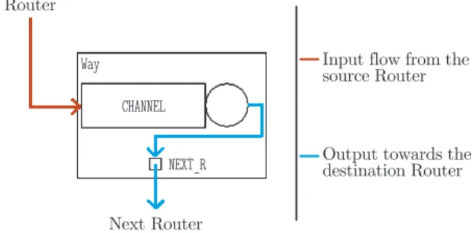
2.2. The Way object
In a computer network, the Way object is a mono directional connection channel between two Routers. It’s a half-duplex connection channel only capable of sending information packets in one direction.
Figure 3. The Way object architecture
Its architecture is shown in Figure 3. This object consists of a queue service device that simulates the transmission delay of a packet transiting on the channel. It has a queuing pointer to which theCPUof the destination Router is assigned as value at the moment of the generation of the computer network model.
TheQNAP2 code for the definition of this object is shown below, with the list of internal variables:
OBJECT WAY(ID, TEM); QUEUE CHANNEL; REF QUEUE NEXT R; REAL TEM;
INTEGER ID; END;
• CHANNEL: is the queue that for a data packet simulates the delay for its trans-mission among the Routers. It forwards packets to theCPUqueue of the Router
after the one where the packets themselves are located.
• NEXT R: is the pointer to the RouterCPUqueue; it’s recalled by theCHANNELqueue.
• TEM: is the average time required for the transmission of a packet. • ID: is the identification of the Way within the network.
2.3. The Line HR object
Line HR is a connection channel between Host and Router within the computer network. Its architecture is shown in Figure 4. The internal R queue
simulates the packet transmission delay within the transmission channel.
Figure 4. The Line HR object architecture
TheQNAP2 code for the definition of this object is shown below, with the list of internal variables:
OBJECT LINE HR(T); QUEUE R;
REF QUEUE ROUT; REAL T;
END;
• R: is the delay center that simulates the transmission time between the Host
and the Router; it forwards the packets to the Router CPUqueue by means of
theROUTpointer.
• ROUT: is the pointer to the RouterCPUqueue.
• T: is the average time required for the transmission of a packet.
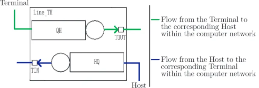
2.4. The Line TH object
This object is a Terminal-Host connection channel within the computer network. It’s a full-duplex channel that allows the flow of packets in both
Figure 5. The Line TH object architecture
communication directions on the line connecting the Host to the Terminal. The architecture of theLine THobject is shown in Figure 5.
TheQNAP2 code for the definition of this object is shown below, with the list of internal variables:
OBJECT LINE TH(TH); QUEUE QH, HQ; REF QUEUE TOUT, TIN; REAL TH;
END;
• QH: is the queue that sends the packets from the Terminal to the destination
Host User queue by means of theTOUTpointer.
• HQ: is the queue that sends the packets from the Host to the destination Terminal Access Hqueue by means of theTINpointer.
• TOUT: is the queue pointer used by theQH queue; it recalls the Host User queue. • TIN: is the queue pointer used by the HQqueue; it recalls the TerminalAccess H
queue.
• TH: is the average time for the transmission of the packet; it simulates the
transmission delay.
2.5. The Host object
The Host object indicates the network devices, both in terms of hardware and software, required by the protocol for the transmission of the packets through the network. This object is modelled for the simulation of the operation of the TCP/IPnetwork communication protocol.
The architecture of the Host object is shown in Figure 6.
TheQNAP2 code for the definition of this object is shown below, with the list of internal variables:
OBJECT HOST(ID);
QUEUE USER, CONTROL, PROTOCOL;
QUEUE ACCESS E, ACCESS R, WINDOW, TIMER, WEBTIMER; REF QUEUE NETWORK;
REF QUEUE HOTE; INTEGER ID; INTEGER ID R; INTEGER WIN SIZE; INTEGER LI, LA;
Figure 6. The Host object architecture
REAL T EMI I, T EMI A; REAL T REC I, T REC A; REAL TIME OUT;
REF PACKET PAK, ANSW;
REF WEBAPP WA; & pointer for web applications END;
• USER: is the queue that receives the data from the Terminal through theLine TH
object and forwards them to theCONTROLqueue.
• CONTROL: is the queue that simulates the sliding window of theTCP/IPprotocol, asks for passage rights to the WINDOWtraffic light and forwards the information
to thePROTOCOL queue.
• PROTOCOL: is the main Host queue. In the management of Web applications, it recalls the PROT WEB procedure. Depending on the application side, Client or
Server, it collects the reception completed ACK, forwards the packets again in case of losses, checked by the Time Out, deletes the packets from the buffer and manages the sequence numbers. This device also forwards to the higher Terminal the data packets reaching the network by means of theHOTEpointer,
which recalls the HQ queue of theLine THobject for connection to the Terminal.
• ACCESS E: is the queue that manages the packets leaving the Host; it recalls the ACC EMI procedure that sets the length of the packets and the times for the
physical transmission towards the network. Moreover, by means of theNETWORK
pointer, it forwards the packet to theRqueue of theLine HRobject that connects to the Router.
• ACCESS R: is the queue that manages incoming packets; it recalls the ACC REC
procedure that sets the length of the packets and the times for their physical reception.
• WINDOW: is a traffic light type queue that manages the requests of passage rights for the packets sent by the CONTROLqueue.
• TIMER: is a queue that saves the transmitted packages. In case of packet loss, or Ack not received within the Time-Out limit period, this device resends a copy of the packet through thePROTOCOL queue.
• WEBTIMER: this queue is only active in case of Web applications; it has the same
function asTIMER, but manages the packets of Web applications.
• NETWORK: is a pointer to theRqueue of theLine HRobject that connects the Host
to the Router. It’s recalled by theACCESS Equeue.
• HOTE: is a pointer to theHQ queue of theLine TH object that connects the Host
to the Terminal. It’s recalled byPROTOCOL.
• ID: is the identification of the Host within the network.
• ID R: is the identification of the Router directly connected to the Host.
• WIN SIZE: is the size of the sliding window of theTCP/IPprotocol.
• LI: is the length of a standard traffic data packet; it’s used for the calculation
of the delay caused by the access queues to theACCESS EandACCESS Rnetwork.
• LA: is the length of a standard traffic Ack; it’s used to calculate the delay caused
by the transmission on the network.
• T EMI I: is the average time taken to emit a byte of a packet on the network.
• T EMI A: is the average time taken to emit a byte of an Ack on the network.
• T REC I: is the average time taken to receive a byte of a packet. • T REC A: is the average time taken to receive a byte of an Ack.
• TIME OUT: is the standard traffic Time-Out; if the Time-Out period is exceeded,
the packet is resent.
• PAK: is a pointer to a standard traffic packet; it’s used in the management of the
data being forwarded.
• ANSW: is a pointer to a standard traffic packet that corresponds to an answer.
• WA: is only present in case of Web application; it’s a pointer to a Webapp. The QNAP2 code below describes the structure of the Protocol queue of a Host of the computer network.
/STATION/
NAME = *HOST.PROTOCOL; SCHED = PRIOR;
SERVICE(EMISSION) = PROT EMI(T EMI I, T EMI A); SERVICE(WEBAP) = PROT WEB(T EMI I, T EMI A); SERVICE(RICHIN) = PROT EMI(T EMI I, T EMI A); SERVICE(RECEPT) = PROT REC(T REC I, T REC A); TRANSIT(RECEPT) = OUT;
The service of a packet in the Protocol queue consists in the calling of a specific service procedure based on the class to which the packet belongs to. The user classes can be:EMISSION,WEBAP,RICHIN,RECEPT.
ThePROT EMIprocedure processes the standard traffic packets issued. This
procedure creates a copy of the packet and passes it to the TIMER queue, which
will send it again to PROTOCOL, should no confirmation ACK be received within the Time-Out period. After the processing time, the procedure also forwards the original packet to theACCESS Equeue, which carries out the physical transmission
of the same through the network.
ThePROT RECprocedure processes the packets received from the network. An initial evaluation is carried out to ascertain if the packet contains ACKor data. In case of data, the packet is passed to the higher Terminal and a confirmation ACKis issued for the source Host that has sent the information. In case ofACK, the packet it refers to is deleted from the timer queue as the communication has been successful.
ThePROT WEBprocedure processes the packets of the Web application being
simulated, and is therefore linked to the Software objects that will be discussed later on. This procedure uses a pointer to the Host object that includes the queue recalling the procedure and an implicit reference to the current user to be treated asWEBAPP, and then carries out a data origin check, ascertaining if they come from
the higher Terminal or the network. This is possible because each packet retains the identification of the Terminal that generated it, but most of all thanks to the one-to-one correspondence between each Terminal and the Host below to which it is linked. In case of data to be transmitted, which means when forwarding a packet to the outside, an exact copy of the same will be created, to be passed to the WEBTIMERqueue, while the packet itself is sent to the ACCESS E queue, so that it can be transmitted to the remote Host for the processing of the Web packet as contemplated on the B side of the processing stage.
2.6. The Terminal object
The Terminal object represents the whole of the local hardware structures of a PC connected to the network, in addition to the resource management software, which in actual facts is normally integrated in the operating system.
The architecture of the Terminal object is shown in Figure 7.
TheQNAP2 code for the definition of this object is shown below, with the list of internal variables:
OBJECT TERMINAL (IDT);
QUEUE USER, ACCESS H, CPU, DISK;
QUEUE SCH, TERM; & Queues, only active for Web Terminals; BOOLEAN ACTIVES;
INTEGER IDT; INTEGER ID H; STRING NAME; INTEGER REQLENGHT; REAL PROCESS, PROC D; REF REQUEST RQ; REF QUEUE PORT; END;
Figure 7. The Terminal object architecture
• USER: is a source that produces standard traffic packets and sends them to the
TerminalCPUqueue. This source is active if the Terminal is not involved in the execution of a Web application.
• ACCESS H: is a queue that receives packets from the Host and sends them to the TerminalSCHqueue. This queue also manages the switch of the Web application
execution side during the simulation, from Client to Server depending on the situation.
• SCH: is a queue that is only active in Terminals involved in the execution of Web
applications. It manages all the operations using an OP variable. The service
procedure of this queue carries out certain operations depending on the value taken on by the OP variable and the side, Client or Server, of execution of the
Web application. For example, depending on theOPvalue, it routes the packets
towards the various CPU, DISK and TERM queues of the Terminal object. This
queue also takes care of the transmission of packets to the Software object Service queue and to theLine TH QHqueue, by means of thePORTqueue pointer.
• CPU: is the queue that simulates the delay caused by the operations that theCPU
must carry out locally. At the end of the service, this queue routes the packets towards the Terminal SCHqueue.
• DISK: is the queue that simulates the delay caused by disk accesses required for
the application. At the end of the service, the packets are routed towards the TerminalSCHqueue.
• TERM: is the queue that simulates the delay of the application due to interaction
with the user. The packets are then routed towards the Terminal SCHqueue. • ACTIVES: is a Boolean variable that indicates if the User source is active, meaning
if standard traffic data packets are generated locally or not. • IDT: is the identification of the Terminal within the network.
• ID H: is the identification of the Host to which the Terminal is connected.
• NAME: is the name of the Terminal.
• REQLENGTH: is the length of a request for the CPU or for the disk in a Terminal
that simulates a standard data flow.
• PROCESS: is the time required by the CPU to complete an operation.
• PROC D: is the time required by the disk to complete an access.
• RQ: is a pointer to a packet generated by the User queue. • PORT: is a pointer to theQHqueue of theLine THobject.
3. The library Software components
In this paragraph we will discuss the software components that allow the modelling of the traffic flows in the computer network. These flows describe two types of traffic that can be found in the simulation of the operation of the computer network. The first type is the so-called standard (or basic) traffic, consisting of flows of packets regarding the generic use of the computer network as telecommunication network. These flows have been analysed in the following publications [4, 5]. The second type is the traffic of packets induced by the execution of a web application on the network.
3.1. The Customer object
The Customer object is a type of object predefined within the framework of QNAP2 programming. This object has been extended with two integer fields to indicate the source Host, SOUR ID, and the destination Host, DEST ID, and two
string fields to indicate the packet type and sub-type,TYPEandTYP. The definition
code is shown below.
CUSTOMER STRING TYP, TYPE;
CUSTOMER INTEGER SOUR ID, DEST ID; REF CUSTOMER C;
3.2. The Paket and Webapp objects
The library includes two new types of objects, which are sub-types of Customer: Paket and Webapp. These objects model the packets relating to the two different types of traffic found on the network: the PAKETobject describes the
generic traffic packet found on the network, which could be defined as standard traffic, while theWEBAPPobject represents a traffic packet induced in the network by
the execution of the web application of which we want to simulate the operation. ThePAKET object also includes fields inherited from CUSTOMER, a DIME
attri-bute, which indicates the byte length of the packet, and a BIRTH field, used for
monitoring the round-trip times of the packet in the computer network. The de-finition code of thePAKETtype object is shown below.
CUSTOMER OBJECT PACKET; REAL BIRTH;
INTEGER DIME; END;
The WEBAPP object has a more complex structure that derives from the
technique used for the description of the flow of the web application packets during its processing, which is completed across the computer network in a distributed manner. The definition code of theWEBAPPtype object is shown below.
CUSTOMER OBJECT WEBAPP;
INTEGER AT, ACPU, AD, N, BCPU, BD; & characterisation of a processing stage INTEGER OP, L;
INTEGER WTOUT; INTEGER SEQ N;
INTEGER APPDESTID, APPDESTNP; INTEGER SSO ID, CLIENT, SERVER, SSO;
INTEGER SOURNP, DEST NP; & Software A and B of the web application; INTEGER ID;
END;
In order to describe the procedure for the execution of a web application on the computer network, we have introduced the processing stage concept. The processing stage starts with the preparation activities on an A Terminal of the network, continues with the transmission of the application packets to a B Terminal of the network, and concludes with the processing of the data received. The model that describes the processing of a web application on the computer network is therefore an ordered and completed sequence of processing stages. The variables within the WEBAPP object used for the characterisation of a web
application processing stage are indicated in the first row of the code defining the
WEBAPPobject above. For this reason, we describe each processing stage as a 𝑛-uple
of six values:
1. ACPU: represents the number of operations to be carried out by the Terminal A
CPUduring the stage.
2. AD: represents the number of disk accesses requested during the stage in
Terminal A.
3. AT: represents an estimate of the time that the application will spend during
the stage for the I/O operations with the user on the A side of the application. 4. N: represents the number of bytes transmitted through the network from
Terminal A to Terminal B during the processing stage.
5. BCPU: represents the number of operations to be carried out by the Terminal B
CPUduring the stage.
6. BD: represents the number of disk accesses requested during the stage to
Terminal B.
In addition to the above six values, the WEBAPP object also contains the
following variables:
• OP: is an integer variable that indicates the next operation to carry out within a stage; for example: access to a disk, network transmission, etc.
• ID: is the identification of theWEBAPP.
• L: is an integer variable that indicates the current application processing stage
• WTOT: indicates the Time-Out period, after which a transmission is considered
as failed and is repeated.
• SEQ N: indicates the position of the packet on the network in the transmission
sequence; it is useful for identifying duplicates at reception. • APPDESTID: is the identification of theWEBAPPdestination. • APPDESTNP: is theWEBAPPdestination port number.
• SSO ID: is the identification of theSSOserver, if present in the system.
• CLIENT: is an integer variable that identifies the Client.
• SERVER: is an integer variable that identifies the Server.
• SSO: is a Boolean variable that indicates if we are in the presence of and SSO
Server.
• SOUR NP: it specifies the Software object of the computer network that has
produced the packet; in theTCP/IP protocol thisID is called port number.
• DEST NP: it specifies the Software object of the computer network to which the
packet is addressed.
The traffic flows in the computer network determined by the two types of objects, Paket and Webapp, trigger traffic flows that differ based on the class to which the packets belong. The computer network standard traffic is characterised by the following user classes:
• EMISSION: is the class of the requests issued by the terminal.
• RICHIN: is the class of the requests received by the terminal.
• ANSWER: is the class of the answers reaching the terminal.
The traffic flow determined by the Webapp packets for the processing of the web application on the computer network is characterised by the Webap user class.
3.3. The Software object
This object appears in the modelling of the processing stages of the web application on the computer network. A Software object is connected to each terminal that is involved in the processing of the web application. The architecture of the Software object is shown in Figure 8.
Figure 8. The Software object architecture
TheQNAP2 code for the definition of this object is shown below, with the list of internal variables:
OBJECT SOFTWARE;
QUEUE PROGRAM, SERVICE; INTEGER EXIT;
INTEGER IDS; INTEGER ROLE; REF FILE FA; REF WEBAPP WA; REF WEBAPP WAAPP;
INTEGER BUF; & support buffer for the swap of source and destination INTEGER C SEQ N;
REAL RUNTIME; END;
• PROGRAM: is the queue that generates the Webapp packets; it assigns the
desti-nation and origin port values. It reads all the necessary data from files. • SERVICE: Main Software queue; it initially recognises if the packet is in a Client
or in a Server, including SSOif present. Depending on the type of application, it creates and sends the authentication cookie, sends the answer to the Server, manages the file download and empties the buffer.
• EXIT: is the identification of the Terminal connected to the Software; it also
coincides with the identification of the Host connected to the Terminal. • IDS: is the Software identification for Client Software; is set to zero for Server
Software.
• ROLE: it identifies the role of the Software; each Software used in the simulation
of a Web application will have a role. The Client will always have role 1, while when present the SSO server will have role 3. These values are independent of the identification of the Terminal and are also used within the simulation to avoid confusion with the identifiers.
• FA: is the pointer to the “server.app” file that contains the model that describes the following stages for the processing of the Web application on the computer network. An example is shown in Figure 11.
• WA: is a pointer to a Webapp, normally used to create and send standard
Webapps.
• WAAPP: is a pointer to a Webapp, mainly used forSSO and non-SSOanswers. • BUF: is the support buffer that gives the possibility of reprocessing the source
and destination IDs once the packet has reached the Software.
• C SEQ N: is the control sequence number, normally set as sequence number of
the latest packet received by the Software.
• RUNTIME: is the Web application processing start time.
4. Model construction
The generation of a computer model network as the one shown in Figure 1 is obtained automatically using a procedure called BuildMod, which reads the network descriptive data from a text file called “Model.dat”.
For each library object type described in this document, the “Model.dat” file contains the list of object realisations found in the model, with the indication of the current values of the individual object internal parameters.
The BuildMod procedure also completes the connections among the indivi-dual realisations of the library objects, determining the global computer network model, with the Software devices needed for the simulation of the execution of a specific Web application.
In Publications [4, 5] we have outline the technique for the generation of a model of telecommunication network based on the use of a descriptive “Mo-del.dat” file and a BuildMod procedure for automatic network model generation through the reading of the data listed in the “Model.dat” file.
In the current framework, the generation of the model is similar to what indicated in the above articles for the evaluation of traffic in telecommunication networks. In this situation, the “Model.dat” file must contain the description of both the Hardware and the Software of the system concerned.
Figure 9 shows the way in which the individual library object realisations are connected to each other within the network. The connection procedure is completed by assigning the appropriate values to the internal pointers of the individual objects.
Figure 9. Local computer network architecture
4.1. Modelling of a web application
Figure 10 describes the sequence for the execution of a web application on the computer network shown in Figure 1. This web application consists in the navigation sequence of a user within a webfarm.
Below are the roles allocated to the various Terminals by means of the “Model.dat” file. Terminal 8 will be connected to Software 1 and will have a role 1, or Client, while Terminals 12 and 13 will be the Servers, with role 2 and 3 and connected to network Software 2 and network Software 3 respectively.
The Client accesses web Server 12 through the browser, with an information request regarding the authentication procedure in order to gain access to the information of that Server. The Client sends information for a total of 5 KB.
Server 12 will send a reply cookie containing the user profile, anXML file containing the Client details. In this case the packet is 35 KB.
The Client will then send a new request to Server 12, also adding to the previously sent information the identification details of the cookie just received and the reception details. This entails a 10 KB packet.
Server 12 now has all the necessary information to respond to the Client and send the requested page. This is a page with a size of 12 KB.
Lastly, the Client adds a further page, belonging to Server 13. However, as there is no activeSSOsystem, in this case the communication between Software 1 on Terminal 8 and Software 3 on Server 13 is carried out exactly as above.
The “Model.dat” file that describes the system model contains a final section for the generation of the Software objects required for modelling the execution of the web application on the computer network. This section consists of a number of records equal to the number of Software objects in the model. The BuildMod procedure reads the records in sequence and for each of them generates the corresponding Software object, indexed in the network based on the generation order. For each Software, the corresponding record will contain the indication of the Terminal to which the Software is connected, the role of the Software in the execution of the application and, if the case, the identification string of the “server.app” file that describes the application. The “server.app” file contains the ordered sequence, in subsequent records, of the web application processing stages. In the file, each application processing stage is described by an 𝑛-uple following the diagram shown in Paragraph 3.2.
The data that in the “Model.dat” file describe the sequence of Software objects that must be generated for the web application characterised by the Sequence diagram shown in Figure 10 are below:
...
& Web Application IDS Exit Role File
1 8 1 server.app; 0 12 2 1;
0 13 3 1;
4.2. The web application processing stages
The “server.app” file, indicated in “Model.dat”, contains the information required for the creation and management of the packets that make up the flow in the computer network for the processing of the web application. “Server.app” is a text file that in the case of the example of the web application described in Figure 10 has the structure described in Figure 11.
In this file, each record represents a web application processing stage, in accordance with the procedure described in Paragraph 3.2. The processing stages
Figure 10. Sequence diagram of a web application
Src Dest Acpu Adisk Aterm Net Bcpu Bdisk 1 2 100 100 500 5000 1500 1500 2 1 100 50 200 35000 1000 500 1 2 100 100 300 10000 400 100 2 1 100 100 300 12000 400 150 1 3 100 100 500 5000 1500 1500 3 1 100 50 200 35000 1000 500 1 3 100 100 300 10000 400 100 3 1 100 100 300 16000 400 150 0 0 -1; && Application end
are listed following the execution sequence from top to bottom. The Src and Dest values correspond to the roles of source Terminal and destination Terminal of the packets during the processing stage, and constitute side A and side B of the processing in accordance with what previously defined. For example, as far as the current web application, Src = 1 and Dest = 2 indicates that the packet left the Terminal with role 1, which is Client 8, to reach the Terminal with role 2, which is Server 12.
We can see that the values of the processing parameters on the B side of the stage, which correspond to the recipient Server, are higher when compared with the ones of the A side. The B side Server must in fact process the authentication requests of the Client, therefore needing a higher number ofCPUoperations and Disk accesses.
The Net field of each record corresponds to the size of the packet sent by A to B during the processing stage. Moreover, the −1 value byACPU in the last record makes it possible to detect the end of the processing activity and terminate the execution of the application.
5. Conclusions
In this work, we have defined a library of objects that gives us the possibility of modelling the operation of a computer network and the traffic of packets induced on the same by the execution of web applications. The objects of this library are mainly defined starting from an architectural framework consisting of a network of queuing service devices. Therefore, starting from a computer network, we can define its model by building the “Model.dat” file that contains the list of the realisations of the library objects corresponding to the individual devices making up the computer network, both as far as Hardware and Software. In a future publication, we will describe the simulators built based on this modelling technique for assessing the processing times of web applications realised using different architectural paradigms.
References
[1] D’Ambrogio A, Iazeolla G and Pasini L 2007 Simulation Modeling Practice and Theory
15 605
[2] Pasini L et al. Queuing networks to evaluate web applications: simulation (in preparation) [3] SimulogQNAP2 Reference Manual version 9.2
[4] Pasini L and Feliziani S 2007TASKQuart. 11 (3) 203 [5] Pasini L and Feliziani S 2009TASKQuart. 13 (4) 315