Available online at http://www.iaeme.com/ijmet/issues.asp?JType=IJMET&VType=9&IType=9 ISSN Print: 0976-6340 and ISSN Online: 0976-6359
© IAEME Publication Scopus Indexed
AUTONOMOUS DETERMINATION OF
PNEUMATIC PARAMETERS OF TRAINDY
L. Cantone
Dept. of Enterprise Engineering “Mario Lucertini”
University of Rome “Tor Vergata”, Via del Politecnico 1, Rome, 00133, Italy G. Arcidiacono, P. Placidoli
Department of Innovation and Information Engineering Marconi University, Via Plinio 44, Rome, 00193, Italy ABSTRACT
TrainDy is the UIC certified software for Longitudinal Train Dynamics (LTD) computation of freight trains. It has been certified after an identification process that has mapped the main pneumatic devices equipping the European freight trains. This identification process has been “manual” (i.e. neither autonomous or automatic) and based on an Experts evaluation to assess its correctness. Such “modus operandi” is not suitable when there is the need for an identification of new devices by a “normal user”. The paper shows the results of an automatic determination process of all pneumatic parameters of TrainDy software in order to have the best matching between experimental measurements and numerical results of three different testing conditions of a 500 m freight train. This determination has been carried out by employing MATLAB and ModeFRONTIER. Results show that the determination process followed by the Expert Group, i.e. identify firstly the pressure in brake pipe, then the pressure in brake cylinder and then compute Longitudinal Forces is not suitable for an automatic determination process, where it is more convenient to optimize all types of tests at the same time.
Key words: freight trains, brake pipe pneumatics, model parameters determination, Longitudinal Train Dynamics (LTD), Optimization.
Cite this Article: L. Cantone, G. Arcidiacono, P. Placidoli, Autonomous Determination of Pneumatic Parameters of Traindy, International Journal of
Mechanical Engineering and Technology 9(9), 2018, pp. 1507–1515.
http://www.iaeme.com/IJMET/issues.asp?JType=IJMET&VType=9&IType=9
1. INTRODUCTION
Even if freight trains provide an environmentally sustainable way to move goods from a place to another, such type of transportation lacks in efficiency, in several European Countries. A way to improve such efficiency is the increase of hauled mass via an increment of train length. The intensification of in-train forces is the biggest obstacle to the increment of trains
mass and length, from the point of view of safety against train derailment (because of excessive in-train compressive forces, according to experimental tests carried out in [1]) and of train disruption (because of high in-train tensile forces). Longitudinal Train Dynamics (LTD) covers, among the others, these issues and [2] reports a recent review on this topic. In order to compute LTD, it is necessary to compute the braking forces, the operational forces (such as forces applied at traction units, running resistance forces, and so on) and in-train forces exchanged by consecutive vehicles during the route. Braking forces mainly depend on emptying of brake pipe (BP) and filling of brake cylinders (BC), among other parameters. Several studies have been developed on this topic and [3] reports one of the most recent.
Differently from previous paper, where design parameters of the components of air brake system, such as nozzles diameter, springs stiffness, cams position and so on are directly managed, this paper is based on pneumatic model introduced in [4], which has been designed to simulate UIC brake by means of some tuning parameters. This pneumatic model, after a validation against experimental data [5]-[6], has been successively incorporated in TrainDy software, which solves the LTD problem [7]. TrainDy, which is an UIC (Union Internationale
Des Chemins de Fer or International Union of Railways) certified software for computation
of LTD of freight trains, is capable to address both Air Pressure Problem and in-train forces computation at the same time. It is considered by European Railway Undertaking the “state of the art” software to perform LTD studies and it has been mentioned in the Open Call text S2R-OC-IP5-01-2018 [8], within the European Shift 2 Rail Project [9]. By this type of tool, it is possible to perform statistical investigations, as those performed in [10] and foreseen by [11]. Statistical investigation of freight trains LTD is a complex issue and it has been addressed, among the others, in [12]-[14].
TrainDy software is currently under development and [15]-[16] and it has been proved to be also a tool suitable for train operation optimization in [17].
The paper expands the work already developed in [18] to an automatic determination of parameters considering not only the air pressure in brake pipe, but also the air pressure in brake cylinders and in-train forces. Automatic determination of model parameters is possible considering more tests at the same time and for all tests where the same device is used, the same tuning parameter is used. Results showed in this paper prove that, by means of an automatic determination of the parameters, it is possible to considerably improve the agreement between numerical and experimental results.
2. MODEL FOR AUTONOMOUS DETERMINATION
TrainDy pneumatic model is based on the numerical integration of Navier-Stokes equations
written under the hypothesis of quasi mono dimensional flow and it relies on some tuning parameters, introduced to improve the computational efficiency of the model and because it is addressed to Railway Undertakings more than to Device Manufacturers. In fact, the TrainDy software is a tool used at UIC level to perform safety analyses of new freight trainsets (having new devices or higher levels of hauled mass and/or train length). Main reason for the need of equivalent parameters is the fact that variable flow sections have been modelled with nozzles of equivalent cross sections.
Tuning parameters are listed below for each pneumatic device or sub-system:
Driver’s brake valve: Diameter of nozzle cross-section (DDBV), for emergency braking.
Accelerating chambers (ACs): Diameter of nozzle cross-section (DAC) that connects the BP to the Volume of accelerating chamber (VAC). Air flows within this volume if pressure in BP is higher than pressure in accelerating chamber and vice-versa.
Control Valve (or Distributor): Pressure loss in BP to activate the filling of accelerating chambers (PactAC); Time to reach the 95% and 100 % of target pressure in brake cylinders (T95 and T100). It is worthwhile remember that previous timings depend on the braking regime (or “brake position”) and they are bounded according to UIC Code 540.
Brake Pipe: Initial pressure in brake pipe (Pini) and concentrated coefficient of pressure loss (K), due to hose couplings between a wagon and another.
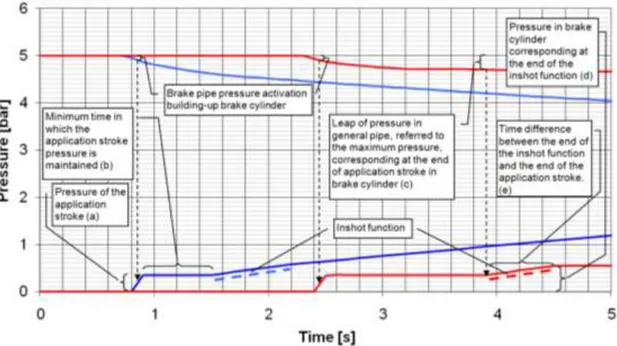
Control Valves (CVs) are characterized by other parameters that are needed to properly fill the BCs during the first phases of “application stroke” (which is the first “jump” of air pressure in BC) and “Inshot function” (which is a linear rising of air pressure in BC); in order to explain the meaning of these parameters it is necessary to refer to Figure 1, which schematically represents the initial filling of first and last brake cylinder and the emptying of brake pipe at first and last wagon.
Figure 1 Time evolution of air pressure in BP and BC, during the first phases of BC filling: application stroke and Inshot function.
Other parameters that are needed to fill the brake cylinders in the initial filling phase are:
Pressure in BC during application stroke (PBCAS)
Minimum duration of application stroke (TAS)
Pressure drop in BP that determines the end of application stroke (PBPAS)
Duration of Inshot function (TIF)
Pressure at the end of Inshot function (PIF)
Last parameter of CV model that needs to be identified is the pressure drop in BP that is needed to start the filling of brake cylinder (PactBC).
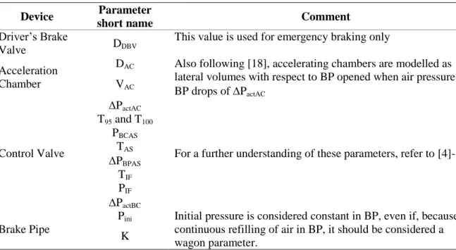
Table 1 reports a summary of above parameters with some comments about their meaning and assumptions.
Table 1 Synthesis table of parameters to be identified for each component.
Device Parameter
short name Comment
Driver’s Brake
Valve DDBV
This value is used for emergency braking only
Acceleration Chamber
DAC Also following [18], accelerating chambers are modelled as lateral volumes with respect to BP opened when air pressure in BP drops of PactAC
VAC
Control Valve
PactAC
For a further understanding of these parameters, refer to [4]-[7] T95 and T100 PBCAS TAS PBPAS TIF PIF PactBC Brake Pipe
Pini Initial pressure is considered constant in BP, even if, because of continuous refilling of air in BP, it should be considered a wagon parameter.
K
From above list, it is straightforward determine the number of parameters to identify for a set of tests: 1 for each DBV, 12 for each CV (2 for the AC and 9 to properly fill the brake cylinders) and 2 for BP. If there are 2 CVs and 1 DBV, as in the results reported hereafter, the parameters number is equal to 27.
Different types of solvers are employed in this paper to obtain the optimal identification: Genetic Algorithms from Global Optimization Toolbox of MATLAB and the solver MOGA from ModeFRONTIER. Description of above optimization techniques is here skipped since it has been already largely provided in [18]. The only point it is worthwhile to mention is that the solver of ModeFRONTIER has been employed using its defaults, while the MATLAB Genetic Algorithms have been launched considering a population size of 512 elements, a crossover fraction equal to 0.9, the “EliteCount” parameter equal to 52 and, finally, the function tolerance set to 10-3. Furthermore, in both cases the solution has been searched within an interval of ±15% around the default values found during TrainDy certification process.
Differently from [18], the parameter to optimize is not the Euclidean Distance between the pints of the curves (numerical and experimental), but the Frechet distance [19] which considers also the similarity of the shapes of the curves: when Frechet distance is equal to zero, the two curves are overlapped.
3. TEST CASE AND RESULTS OF IDENTIFICATION
In this paper, the identification is performed on three tests that refer to a freight train of 500 m length (coming from DB AG). The train performs:
T2. An emergency braking from 20 km/h
T3. An emergency braking from 25 km/h and 40 mm of gap between the buffers of consecutive wagons.
The control valves of the vehicles are two (one for the traction unit and another type for all wagons) and there is only one traction unit at the beginning of the train.
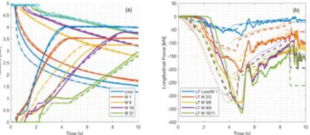
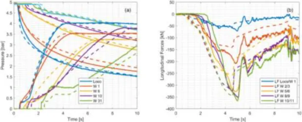
Before showing the results of identification, Figure 2 reports the time evolution of air pressure in BP and in BCs (a) for three cases: experimental measurement (solid), certified version of TrainDy (dashed), version of TrainDy under development with the new solver for pneumatic equations described in [18] (dotted). In Figure 2 (b) the time evolution of in-train forces for the same cases above is displayed: results of Figure 2 refer to an emergency braking from 25 km/h and without any gap (T1). Table 2 reports the Frechet distance with respect to experimental measurements considering certified version and “under development” version of TrainDy with new solver of pneumatic equations: new numerical method to solve pneumatic equations gives some benefits in reducing Frechet distance.
Figure 2 Time evolution of pressure in BP and BC (a) and of longitudinal forces (b). Table 2 Curves similarity expressed by Frechet distance.
Type Reference/Experimental New Solver/Experimental
Pressure in BP 0.61988 0.56316
Pressure in BC 1.0379 1.0632
Longitudinal forces 133.81 130.94
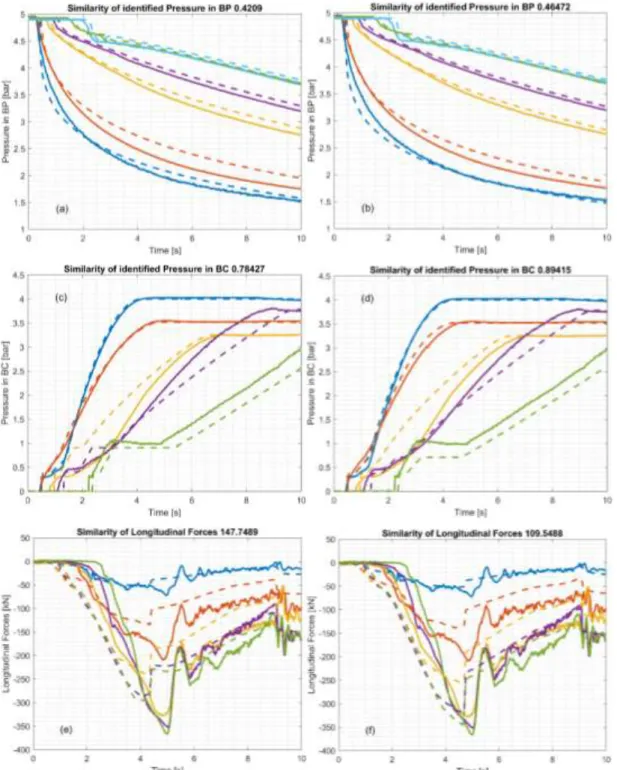
Figure 3 reports the time evolution of pressure in BP (a) and (b), in BC (c) and (d) and longitudinal forces (e) and (f) for T1; solid lines are used for experimental measurements and dashed lines for numerical computations. Identified parameters have been computed by MATLAB Genetic Algorithms. Results on the left side of Figure 3 have been computed by optimizing Frechet distance for air pressure only (in BP and in BC), whereas results on the right have been computed by optimizing Frechet distance considering also Longitudinal Forces. It is worthwhile remember that all the parameters that need to be identified have a direct effect on air pressure behaviour but they have also a non-direct effect on Longitudinal Forces; this is the reason why during the certification the parameters have been (manually) identified considering only the air pressure in BP and BC. Autonomous determination allows the optimization of both pneumatics and dynamics which is not suitable manually: values of Frechet distance show that this approach brings better results.
Figure 3 Time evolution of pressure in BP (a)-(b), in BC (c)-(d) and of longitudinal forces (e)-(f). In (a), (c) and (e), only pneumatics has been optimized; in (b), (d) and (f) both pneumatic and dynamics
are optimized.
Comparison of Figure 3 (a) and (b) and of (c) and (d) show that by optimizing both pneumatics and dynamics there is a significant improvement of dynamics and a minor worsening of pneumatics.
Since above simulations have proved that is better to identify the parameters by optimizing both pneumatics and dynamics, simulation with ModeFRONTIER have been performed only in this condition. Figure 4 shows the time evolution of air pressure in BP and BC in (a) and of longitudinal forces in (b) for the best results obtained by MOGA solver of
ModeFRONTIER: as before, solid lines are used for experimental measurements and dashed lines for numerical computations. As before, Figure 4 refers to T1.
Figure 4 Time evolution of pressure in BP and BC (a) and of longitudinal forces (b), for identification performed with ModeFRONTIER.
Even if it is not so clear from the pictures, ModeFRONTIER solver finds a better optimum with respect to MATLAB solver; Table 3 reports, for all three tests, the percentage differences with respect to the maximum experimental in-train compressive force. In Table 3, column “Certified” reports the difference with respect to experimental measurements of
TrainDy certified version, where the identification has been performed by an Expert Group.
Table 3 Percentage difference in terms of maximum in-train compressive force Test Certified MATLAB ModeFRONTIER
T1 -10.30 -5.783 -5.051
T2 -16.59 -10.78 -10.11
T3 -9.897 -7.426 -6.745
4. CONCLUSIONS
The UIC TrainDy software is considered by European Railway Undertakings the state of the art to determine in-train forces for freight trains. It has been validated and certified by a comparison against more than 30 experimental tests provided by DB AG, SNCF and TRENITALIA. Its pneumatic model has a set of equivalent parameters that have been identified by an Expert Group evaluation. This approach can be overcome by an automatic determination as that proposed in this paper. Showed results demonstrates that it is preferable to identify the parameters by optimizing pneumatics and dynamics at the same time, which is too hard to accomplish by a manual identification. By means of the autonomous determination, it has been possible to considerably reduce the difference between the numerical and experimental results in terms of maximum compressive in-train forces, which are very important to assess the safety of a train composition. As a consequence, the autonomous determination process is capable to improve TrainDy accuracy. As a further future development of the present research the authors are evaluating the usefulness of the application of Axiomatic Design [20].
REFERENCES
[1] European Institute for Railway Research, ERRI B177.5/RP1 Etude del probabilities de derailment de trains de marchandises sous l’influence d’efforts longitudinaux de compression eleves, 1999.
[2] Cole, C., Spiryagin, M., Wu, Q. et al. Modelling, simulation and applications of longitudinal train dynamics. Vehicle System Dynamics, 55(10), 2017, pp. 1498-1571. [3] Wei W., Hu Y., Wu Q., Zhao X., Zhang J. and Zhang Y. An air brake model for
longitudinal train dynamics studies. Vehicle System Dynamics, 55(4), 2017, pp. 517-533. [4] Cantone, L., Crescentini, E., Verzicco, R., Vullo, V. A numerical model for the analysis of
unsteady train braking and releasing manoeuvres. Proc. IMechE, Part F: J. Rail and Rapid Transit, 223(3), 2009, pp. 305-317.
[5] Cantone, L., Palazzolo, A. Pneumatic validation of traindy with Trenitalia experimental data [Validazione pneumatica di TrainDy con dati sperimentali Trenitalia]. Ingegneria Ferroviaria, 63(5), 2008, pp. 409-418.
[6] Cantone, L., Negretti, D., Palazzolo, A., Karbstein, R. Dynamic validation of the new International Union of Railways (UIC) simulator for the longitudinal dynamics of trains, namely, TrainDy with experimental data from Deutsche Bahn (DB) and Trenitalia [Validazione dinamica di TrainDy con dati sperimentali DB e Trenitalia]. Ingegneria Ferroviaria, 64(2), 2009, pp. 165-172.
[7] Cantone, L. TrainDy: the new Union Internationale Des Chemins de Fer software for freight train interoperability. Proc. IMechE, Part F: J. Rail and Rapid Transit, 225(1), 2011, pp. 57-70.
[8] https://ec.europa.eu/research/participants/portal/desktop/en/opportunities/h2020/topics/s2r -oc-ip5-01-2018.html
[9] https://shift2rail.org/
[10] Cantone, L., Ottati, A. Methodologies for the hauled mass increase of freight trains in accordance with Fiche UIC 421 [Metodologie per l'incremento della massa rimorchiata dei treni merci in conformité alla Fiche UIC 421]. Ingegneria Ferroviaria, 70(2), 2015, pp. 109-128.
[11] UIC 421 OR, January 2012, Rules of the consist and braking of international freight trains, 9th edition.
[12] Ansari, M., Esmailzadeh, E., Younesian, D. Longitudinal dynamics of freight trains. In. J Heavy Veh Syst, 16(1/2), 2009, pp. 102–131.
[13] Arcidiacono, G., Berni, R., Cantone, L., Nikiforova, N.D., Placidoli, P. Fast method to evaluate payload effect on in-train forces of freight trains. The Open Transportation Journal, 12(1), pp.77-87, 2018.
[14] Arcidiacono, G., Berni, R., Cantone, L., Placidoli, P. Kriging models for payload distribution optimisation of freight trains. International Journal of Production Research, 55 (17), 2017, pp. 4878-4890.
[15] Arcidiacono, G., Cantone, L. A Model of Control Valve for Wagons Equipped by k-Blocks. International Journal on Advanced Science, Engineering and Information Technology, 8(1), 2018, pp. 285-290.
[16] Cantone, L., Ottati, A. Modelling of friction coefficient for shoes type LL by means of polynomial fitting. The Open Transportation Journal, 12(1), 2018, pp. 114-127.
[17] Cantone, L., Arcidiacono, G. A Study on Releasing Manoeuvre to Improve Freight Safety and Efficiency. International Journal of Mechanical Engineering and Technology, 9(3), 2018, pp. 899-909.
[18] Arcidiacono, G., Placidoli, P., Cantone, L. Automatic Identification of Tuning Parameters of Brake Pipe Pneumatic Model. International Journal of Mechanical Engineering and Technology, 9(2), 2018, pp. 829-838.
[19] T. Eiter and H. Mannila. Computing discrete Frechet distance. Technical Report 94/64, Christian Doppler Laboratory, Vienna University of Technology, 1994.
[20] Arcidiacono G., Yang K., Trewn J., Bucciarelli L., Application of Axiomatic Design for Project-Based Learning Methodology. Procedia CIRP, 53, 2016, pp. 166-172