Università degli Studi di Pisa
Corso di Dottorato di Ricerca in
Ingegneria Meccanica
Comportamento strutturale di elementi
innovativi di batterie di perforazione
Tesi svolta per il conseguimento del titolo di dottore di ricerca
Allievo:
Ing. Ivan BALANDIN
Tutori:
Prof. Leonardo BERTINI (DIMNP, Università di Pisa) Prof. Marco BEGHINI (DIMNP, Università di Pisa)
VI Ciclo
Anno 2008
UNIVERSITÀ DI PISA
Scuola di Dottorato in Ingegneria “Leonardo da Vinci”
Corso di Dottorato di Ricerca in
INGEGNERIA MECCANICA
Tesi di Dottorato di Ricerca
COMPORTAMENTO STRUTTURALE DI
ELEMENTI INNOVATIVI DI BATTERIE DI
PERFORAZIONE
Autore:
Ing. Ivan Balandin
Anno 2009
Relatori:
Prof. Leonardo Bertini Prof. Marco Beghini
ABSTRACT
Torque and drag occurred during the drilling of an extended-reach well, when the drillstring is pushed through the long horizontal hole section is a limiting factor for conventional drill pipe technology presented by standard steel drill pipes. A drill pipe with enhanced buoyancy in the drilling fluid, that fills the well during drilling, could decrease the weight of the entire drillstring in the well and solve the problem. A drill pipe made of a high strength aluminum alloy and having cavities inside the pipe body wall, void or filled with specific light-weight material, could provide such a buoyancy effect. Once a feasible configuration is found, such a Buoyant Aluminum Drill Pipe (BADP) can be produced at Kamensk-Uralsky Metallurgical Works (KUMW). To evaluate possible advantages of the BADP in extended-reach drilling (ERD) a joint research project have been initiated by ENI SpA (E&P division), the Department of Mechanical, Production and Nuclear Engineering of the University of Pisa, and KUMW.
The objective of the work described in this Ph.D. thesis is to evaluate the conceptual design of BADP, proposed by drilling engineers from ENI SpA, containing it within limiters like mechanics, hydraulics, industry standards, manufacturability, etc.
The aluminum pipe body is planned to be produced at KUMW by a hot extrusion process, pushing material through a die of the desired cross-section. An extremely high pressure is used in extrusion to squeeze the metal out into the desired form. Hence, a specific extrusion die is needed every time to produce pipes with a new cross-section and can cost $10000 in case of BADP extrusion. Keeping it in mind, before the first full scale specimen is produced, we needed to extensively analyze a quantity of different BADP cross-sections evaluating possible length of an extended-reach well (ERW) they permit to drill, to find a feasible solution that meets ERD requirements and has an essential advantage over conventional drill pipe.
The BADP designing process is based on the developed tool enabling parametric study of different configurations of the BADP pipe body cross-section. Exhaustive enumeration algorithm based completely on the calculation of explicit equations was realized in MATLAB®. It permits to define a maximum possible length of ERW at specified vertical depth for each BADP cross-section configuration analyzed, provided that the maximum equivalent stress in the section does not exceed a maximum permissible level.
The BADP behavior under the hydraulic pressure exerting inside and outside the pipe, differs from that one of conventional pipe. Due to presence of ribs in the BADP cross-section, the pressure causes stress concentrations typical for bending, whereas in conventional pipes hoop and radial stresses can be evaluated by means of equations of Lamè. Here the effect of ribs presence was assessed by means of the finite element analysis carried out in ANSYS®. Then stress correction factors were determined for each BADP configuration analyzed. Multivariable regression method was then used and implemented in MATLAB® to find analytical equations enabling to predict the stress correction factors as a multivariable function of configuration parameters of BADP cross-section. The usage of a full cubic polynomial permitted the mean error of prediction not to exceed 5%.
The algorithm was used to find an optimal BADP configuration enabling maximum horizontal extent of wells with standard diameters used in ERD, 215.9 and 244.5 mm. Explicit equations composing the developed algorithm was then used to evaluate performance of standard aluminum and steel drill pipes in drilling the wells of the same standard diameters. Two types of treaded conical connections were compared to find an optimal one to be used with BADP. Trapezoidal and triangular shapes of threads were analyzed. Results are extensively discussed in the present thesis.
SOMMARIO
Le forze di attrito che si presentano durante la perforazione di un pozzo di tipo “extended-reach”, quando la batteria di perforazione (DS) si muove in direzione assiale dentro una lunga sezione orizzontale del pozzo, limitano le caratteristiche operative della tecnologia convenzionale delle aste di perforazione (DP) standard di acciaio. DP con geometria modificata al fine di produrre galleggiamento (incentivato dalla presenza del fango di perforazione, che riempie il pozzo durante la perforazione) possono ridurre il peso dell’ intera DS nel pozzo. DP in lega di alluminio ad alta resistenza con le cavità nella parete, vuote o riempite con un materiale adatto di basso peso, potrebbe fornire tale effetto galleggiante. Una volta definita una configurazione di DP galleggiante valida, tale asta potrà essere prodotta da “Kamensk-Uralsky Metallurgical Works” (KUMW). Un progetto di collaborazione è stato intrapreso, fra il DIMNP, ENI SpA (divisione E&P) e KUMW, per valutare I possibili vantaggi della BADP in perforazione di tipo “extended-reach” (ERD). L’obbiettivo del lavoro descritto nella presente tesi di dottorato, è quello di definire il progetto concettuale della BADP, proposto dagli ingegneri di ENI, assecondando i vincoli di resistenza meccanica dei materiali, idraulica, standardizzazione industriale e fattibilità tecnologica.
Le aste di alluminio verranno prodotte da KUMW per estrusione a caldo, forzando il materiale attraverso una matrice della forma della sezione desiderata. La pressione di estrusione richiesta è molto elevata per produrre l’estrusione. Per cui, una specifica matrice è richiesta per produrre una nuova geometria, con un costo di 10000$ ciascuna. Dato l’elevato costo è stato valutato attentamente il progetto, al fine di evitare inutili costi e sprechi.
Il progetto della BADP è basato sullo sviluppo di strumenti in grado di permettere studi parametrici delle differenti configurazioni della sezione della BADP. Gli algoritmi numerici utilizzati sono stati implementati in MATLAB®. È possibile definire la massima lunghezza del ERW data una specifica profondità verticale, per ciascuna sezione della BADP, imponendo che la massima tensione nella sezione non superi il livello ammissibile del materiale.
L’effetto sullo stato di tensione prodotto dalla pressione, interna al tubo sia esterna, è diverso rispetto alle DP convenzionali (o standard). Per effetto della presenza delle alette, nella sezione della BADP, la pressione genera delle concentrazioni di tensioni flessionali sugli elementi della sezione, mentre nelle DP standard si generano soltanto le tensioni circonferenziale e radiale che possono essere determinate mediante la teoria di Lamè. L’effetto delle alette è stato valutato mediante gli elementi finiti (usando il software Ansys®), determinando i fattori di concentrazione delle tensioni per ogni sezione di BADP. Una regressione lineare multivariabile è stata implementata in MATLAB® per trovare un’espressione analitica in grado di prevedere i coefficienti di concentrazione per una generica sezione BADP. È stata usata una polinomiale cubica, che ha garantito un errore non superiore al 5%.
L’algoritmo è stato usato per trovare la configurazione ottima della sezione BADP, al fine di massimizzare la possibile estensione orizzontale del pozzo (con diametro del pozzo standard di 215.9 mm e 244.5 mm).
Equazioni esplicite sono state usate per valutare le prestazioni nelle stesse condizioni di aste standard al fine di validare la geometria suggerita per confronto con le aste standard. Infine, due tipi di connessioni filettate coniche sono state comparate per individuare quella ottima da essere usata nella BADP. Le forme triangolare e trapezoidale dei filetti sono state confrontate. I risultati sono confrontati e discussi nella tesi.
A
CKNOWLEDGEMENTSFirst of all I would like to express my appreciation to my supervisors Prof. Leonardo Bertini and Prof. Marco Beghini for giving me the opportunity to perform this research, for important advices and continual support during my PhD study. I frankly appreciate the liberty of creativity and the confidence given to me.
I express my special cordial gratitude to Baryshnikov Anatoly Ivanovich, Coordinator of International Standardisation from Eni S.p.A., for his numerous ideas, useful discussions and important advices, without which this dissertation would not have been completed. Also I would like to thank Antonino Merlo, from ENI S.p.A. E&P Division Drilling & Completion Research Department, for his constructive collaboration and technical support.
I am very grateful to Dr. Ciro Santus for his valuable assistance in the ANSYS programming and important suggestions throughout my course of PhD.
My deep gratitude and obligation goes to Prof. Gino Dini for his indulgence and understanding without which this dissertation would not have been accepted. I am grateful to my friends for all their support and readiness to help.
I whole-heartedly thanks my parents and my parents-in-law for their love, parental care and all-embracing support.
Finally, my sincere gratitude goes to my wife Lelya Zhornyak for her invaluable support, inspiration and constant encouragement during my work.
INDICE
1. INTRODUCTION... 1
1.1 Oil and gas drilling... 1
1.1.1. Drilling fluid (drilling mud)... 1
1.1.2. Drillstring... 2
1.1.3. Drilling rig... 3
1.1.4. Horizontal drilling... 5
1.2 Problems in ERD...7
1.3 Conceptual design of Buoyant Aluminum Drill Pip... 9
1.3.1. Buoyant aluminum drill pipe... 9
1.3.2. BADP advantages and disadvantages in ERD... 10
1.3.2.1 The advantages... 10
1.3.2.2 The disadvantages... 11
1.4 Outline of the Thesis... 13
2. MATERIALS... 16
2.1 Design characteristics for drill pipes material selection... 16
2.1.1. Specific strength... 16
2.1.2. Elastic properties... 18
2.1.3. Drillstring handling... 19
2.2 ISO 15546, group II Aluminum alloy... 19
2.2.1. Chemical structure analysis... 20
2.2.2. Static tensile test results... 20
2.2.3. Material yield strength dependency on temperature... 22
3. DRILLSTRING THEORY... 24
3.1 Drill pipe loading conditions... 24
3.2 Theoretical models for drillstring design in horizontal drilling... 25
3.2.1. Drillstring buckling in long horizontal wells... 26
3.2.1.1 Sinusoidal buckling... 26
3.2.2.2 Helical buckling... 27
3.2.2. Torque and drag model... 29
3.2.2.1 Combined friction for simultaneous hoisting and rotation of drillstring... 29
3.2.2.2 Torque and drag calculation... 31
3.2.2.2.1. Drilling operation………..…... 32
3.2.2.2.2. Lowering operation………..……... 32
3.2.2.2.3. Hoisting operation………...….. 32
3.2.3. Drilling mud hydraulics... 33
3.2.3.1 Drilling mud circuit... 33
3.2.3.2 Drilling mud model... 34
3.2.3.3 Flow regime determination... 35
3.2.3.5 Discharge pressure at the mud pumps (SPP)... 38
3.2.3.6 Equivalent circulating density... 39
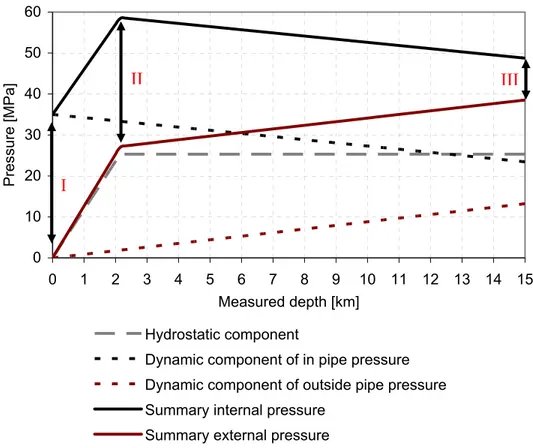
3.2.3.7 In pipe and outside pipe pressure... 40
3.2.4. Thick cylinder theory... 41
2.2.4.1 Loading by internal pressure (Pe = 0)... 42
2.2.4.2 Loading by external pressure (Pi = 0)... 42
4. DEVELOPMENT OF AN ANALYTICAL MODEL FOR SIMULATING MECHANICAL BEHAVIOR OF BADP UNDER PRESSURE... 44
4.1 Equivalent stress distribution for different loading conditions... 45
4.1.1. Finite element model... 45
4.1.1.1 Model configuration and boundary conditions... 45
4.1.1.2 Model of the material behavior... 46
4.1.2. Drillstring critical sections and loads applied... 46
4.1.3. Analysis of stress-strain state in the BADP pipe body under pressure... 50
4.1.4. Bending stress factor... 64
4.2 Bending stress factor prediction by Linear multivariate regression... 64
4.2.1. Bending stress factor... 64
4.2.2. Multivariate linear regression... 69
4.2.3. Regression analysis results... 71
4.2.4. Analytical model validation and interpolation accuracy 76 5. DESIGN OPTIMIZATION OF BADP PIPE BODY... 86
5.1 Problem formulation... 87
5.1.1. Configuration... 87
5.1.2. Specifications... 89
5.1.3. BADP feasibility criteria ... 90
5.1.3.1 Model configuration and boundary conditions... 90
5.1.3.2 Condition of bottom hole formations integrity... 91
5.1.3.3 Stand pipe pressure criterion... 91
5.1.3.4 Efficiency criterion for the drilling mud circulation process... 92
5.1.3.5 Prvention of buckling during the drill string lowering and drilling... 92
5.1.3.6 Torque limit ... 93
5.1.3.7 BADP pipe body strength criterion ... 93
5.1.3.8 Feasibility threshold... 94
5.2 Designing process... 96
5.3 Analysis results... 99
6. ANALYSIS OF SHEAR STRENGTH OF DRILL PIPE TRHREAD CONNECTIONS... 105
failure... 105
6.2 The calculation of a shear strength of ZL-type threaded TJ connection with triangle thread profile... 108
6.3 The shear failure calculation of ZLK-type threaded connection with a trapezoidal thread profile, conical shoulder and stop face... 110
6.4 Torsional strength of ADP–STJ connection of different types... 111
6.4.1. ZL-type threaded ADP-STJ connection with triangular thread rofile... 111
6.4.2. ADP and ZLK-type connection assembled with “cold” and “hot” techniques... 113
6.5 Summary... 114
6.CONCLUSIONS... 115
BIBLIOGRAPHY... 117
APPENDIX A (ANSYS batch file. 2D model of Buoyant Aluminum Drill Pipe (body pipe cross-section))... 123
APPENDIX B (ANSYS batch file. Preliminary parametric study of BADP elastic behavior under pressure)... 127
APPENDIX C (MATLAB batch file. Calculation of the hoop and radial stresses in BADP using analytical model based on cubic multivariate polynomials (the model validation test))...127
APPENDIX D (MATLAB batch file. Optimization calculation of BADP. Parametric analysis with well depth, Lv, well horizontal extent, Lh and BADP section geometric parameters (h, si, se, t and d1) as design variables)... 131
CHAPTER 1
INTRODUCTION
1.1
Oil and gas drilling
General information about the industry the present research concerns as well as key definitions used in the present thesis are given below.
An oil well or a gas well are general terms for any boring through the Earth's surface designed to find and produce hydrocarbons. The well is created by drilling a hole (wellbore) of ca. 100 mm to 1000 mm diameter into a rock vertically, directionally or horizontally (Fig. 1.1).
Fig. 1.1 - Oil and gas drilling. (a) Vertical and directional drilling. (b) Horizontal drilling. (b) Horizontal drilling (a) Directional drilling Vertical drilling
The drilling process consists in cutting the rock with rotating drill bit (or bit), provided with axial load and hydraulic power.
1.1.1. Drilling fluid (drilling mud)
To bring out the cuttings genrated by the bit at the bottomhole, drilling fluid (or drilling mud) is used. The cuttings are swept up by the drilling fluid as it circulates back to surface outside the drill pipe. The fluid then goes through shakers which strain the cuttings from the fluid. Then clean mud is pumped again into the hole. This process is referred to as a driling mud circulation.
Drilling mud is a complex mixture of fluids, solids and chemicals which must be carefully tailored to provide the correct physical and chemical characteristics required to safely drill the well. Drilling mud is generally a viscous, heavy fluid (usually 1 to 2 times water density) designed to perform a variety of functions. Salient functions of drilling muds are given below:
- To prevent the formation fluids from entering into the hole and result in disaster as a blow out by exerting sufficient pressure against the formations being drilled.
- Keep the bit cool and clean during drilling. - Bring out the cuttings generated by the bit.
- Should be able to keep the cuttings in suspended form during the mud pump stop.
- Should have minimum interaction with the exposed formations.
1.1.2. Drillstring
A drillstring (DS) is a column of drill pipes that transmits drilling fluid (via the mud pumps) and rotational power (via the kelly drive or top drive) to the bit. The term is loosely applied as the assembled collection of the drill pipe, drill collars, tools and drill bit (Fig. 1.2).
The drillstring is hollow so that drilling fluid can be pumped down through it and circulated back up the annulus (void between the drill string and the formation).
Fig. 1.2 - Components of a typical drillstring for horizontal drilling Bit Downhole motor (DM) Drill pipe (DP) Heavy Weight Drill Pipes (HWDP) Drill Collar DC HWDP DP (DC) TJs Tool Joint (TJ)
The drill string is typically made up of 4 sections:
- Bottom hole assembly (BHA). The BHA is made up of a drill bit, drill collars (DCs) which are heavy, thick-walled pipes used to apply weight to the bit, and stabilizers which keep the drilling assembly centered in the hole. The BHA contains DC only in case of vertical or directional drilling, when almost the entire drillstring is in tension and DC is in compression (Fig. 1.3). In horizontal drilling DC is set in vertical or inclined section, where generates and transports the weight to the DP placed in wellbore horizontal section. So, in horizontal drilling, the drillstring placed in horizontal section is entirely in compression during drilling. The BHA may also contain other components such as a downhole motor, Rotary Steerable System, measurement while drilling (MWD), and logging while drilling (LWD) tools.
- Transition pipe (often Heavy Weight Drill Pipe). Heavyweight drill pipe (HWDP) is placed between the drill collars and drill pipe. HWDPs usually have thickening in the middle of the pipe body. The function of the HWDP is to provide a flexible transition between the drill collars and the drill pipe. This helps to reduce the number of fatigue failures seen directly above the BHA. A secondary use of HWDP is to add additional weight to the drill bit.
- Drill Pipe. Drill pipe (DP) makes up the majority of a drill string. A drill string is typically about 2000 - 3000 m in length for a conventional onshore oil or gas drilling and may extend to over 10000 m for drilling of an offshore deviated well. DP structurally is the weakest component of a drillstring. Hence, it represents structural properties of entire drillstring.
- Drill Stem subs. Drill stem subs are used to connect drill string elements with different threads at the ends.
Each section is made up of several components and joined together using special tapered threaded connections known as tool joints (TJs). TJs are connected by applying a proper make up torque obtaining static friction bond.
Most components in a drillstring are manufactured in 9 m (range 2, [1]) lengths, although they can also be manufactured in 13.5 m (range 3) lengths. Each 9-m component is referred to as a joint. Typically 2, 3 or 4 joints are joined together to make a stand. The length of Aluminum DP joint can be 12.5 or 14 m.
1.1.3. Drilling rig
Pulling the drillstring out of or running the drill string into the hole is referred to as tripping. Drill pipe, HWDP and collars are typically tripped in stands to save time. So, routine drilling consists of continuously drilling increments the length of one stand, making connections or adding to the drillstring another stand. This drilling continues until the drill bit must be changed. Changing the bit is also called making a trip. A round trip is simply coming out of the hole, changing the bit, and going back into the hole.
This process is facilitated by a drilling rig (Fig. 1.3) which contains all the necessary equipment to circulate the drilling fluid, hoist and turn the pipe, control downhole pressures, remove cuttings from the drilling fluid, and generate onsite power for these operations.
There are two drilling methods that are different in drillstring functions during the drilling process. The first one is a rotary drilling, when the torque on bit and hydraulic power are generated by the drilling rig equipment at the surface (rotary table, see Fig. 1.3) and transported by the drillstring to the bit. In this case, the drillstring transports weight, torque and hydraulic power to the bit.
Fig. 1.3 - Drilling rig
BHA 100-300 m 1-12 km Rotary table Compression Tension Bit Drill collar Drill pipe Drawworks From mud pump 30-80 m Top drive Hook Hoisting system
When downhole motor (DM) drilling takes place, the drillstring does not rotate and torque is generated by the DM connected to the bit. The DM transforms hydraulic power of drilling fluid to rotational movement and torque is generated at the bottomwhole. In this case the bit is rotated by the DM (turbine DM or screw one) and the entire drillstring moves axially in sliding mode. Drilling of wells with long horizontal sections is often commenced implementig combined downhole motor and rotary drilling, where drillstring is rotated by the top drive system (top drive in Fig. 3) to overcome friction occurred in horizontal section.
1.1.4. Horizontal drilling
Before the 1970s most oil and gas wells were vertical. Then first downhole motors have occurred and directional drilling has begun developing. It created new opportunities to extract hydrocarbons from formations that were not accessible with vertical drilling earlier. Following innovations in oil and gas drilling industry made it possible to produce a well with horizontal section drilled in reservoir.
river buffer buffer private land pay zone wetland pay zone pay zone pay zone
Fig. 1.4 - Directional drilling applications
A horizontal well is commonly defined as any well in which the lower part of the well bore parallels the pay zone. The angle of inclination used to drill the well does
not have to reach 90° for the well to be considered a horizontal well. Over the last 20 years drilling horizontal wells have become a preferred method of oil and gas recovering from reservoirs in which these fluids occupy strata, that are horizontal, or nearly so, because they offer greater contact area with the productive layer than vertical wells. It gives enhanced oil and gas production.
The main purposes that directional wells are drilled for are presented below:
- Increasing the exposed section length through the reservoir by drilling a hole at an angle.
- Drilling into the reservoir where vertical access is difficult or not possible. For instance, it may be an oilfield under a town, under a lake, or underneath a difficult to drill formation (see Figure 4).
- Allowing more wellheads to be grouped together on one surface location can allow fewer rig moves, less surface area disturbance, and make it easier and cheaper to complete and produce the wells. For instance, on oil platform, up to about 40 wells can be grouped together. The wells will fan out from the platform into the reservoir below. This concept is being applied to land wells, allowing multiple subsurface locations to be reached from one pad, reducing environmental impact.
- Drilling "relief wells" to relieve the pressure of a well producing without restraint (a blowout). In this scenario, another well could be drilled starting at a safe distance away from the blow out, but intersecting the troubled wellbore. Then, heavy fluid (kill fluid) is pumped into the relief wellbore to suppress the high pressure in the original wellbore causing the blowout.
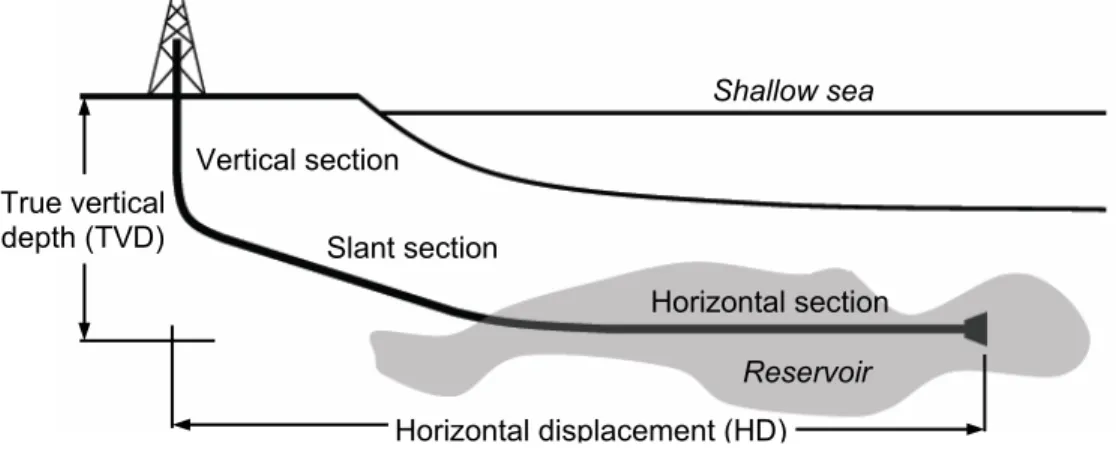
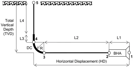
The term extended-reach drilling (ERD) suggests a well with horizontal displacement (HD) to true vertical depth (TVD) ratio to be more than 2 [2] (Fig. 1.5).
Fig. 1.5 - Extended-reach well True vertical depth (TVD) Horizontal displacement (HD) Reservoir Shallow sea Horizontal section ection Slant s Vertical section
Oil companies continually search for the most cost effective way to exploit reserves, particularly those that lie some distance from existing infrastructure. In the past, the only way to exploit these was through investment in new drilling and production facilities in the reserves vicinity. This necessity was challenged in the mid 1990s when BP drilled wells that stretched 5 km then 8 km and then 10 km offshore from the rig site located onshore at their Wytch Farm development [1]. It was anticipated that the technical success of this project would encourage a number of similar projects and ERD would become “standard practice.” Indeed, nowadays ERD has become an enabling technology with confirmed ecological and economical efficiency and hundreds of wells have been constructed with departure from vertical in excess of 5000 m [3].
Two world record-breaking extended-reach wells (ERWs) drilled in 2008 represent state-of-the-art ERD technology and inherent challenges. The first record was established in the Exxon Neftegas Limited Chayvo field offshore Sakhalin Island in Russia, north of Japan. In a field holding 17 of the world’s 30 longest ERD wells, a 3661-m 216-mm horizontal hole section of Chayvo Well Z-12 was drilled to a 11680 m measured depth (MD), or the total length of the wellbore, while maintaining a true vertical depth (TVD) at 2600 m, breaking the previous world record set on Well Z-11 by 398 m [4].
The Chayvo Z-12 record had been held for only four months when Maersk Oil Qatar in May drilled Well BD-04 on the Al Shaheen field offshore Qatar to a world record length of 12300 m with a horizontal section of 10900 m, besting the Chayvo Z-12 MD by 61 m. The BD-04 well was drilled in 36 days and was incident-free.
1.2
Problems in ERD
In both the cases mentioned above ERD limitations involved hard operating conditions for DS in long horizontal hole section. Transfer of axial load to the bit and high torque developed by increased friction forces with DS running and rotation were a challenge with increasing length. The torque during the drilling of last sections of the record wells was extremely high (50-80 kNm) [4], [5] and ones of the most powerful top drives (TDS-4S and TDS-8S) and torque resistant TJs (HT50 and XT57) in the industry were used. The critical parameter in producing resistance forces (friction) during DS running and rotation is the DS weight, since the main part of a DS is placed horizontally or quasi-horizontally and its almost entire weight is distributed on the lower wellbore wall [6].
Another problem can occur during drilling is buckling. Since axial load is applied to the drill pipe placed in the horizontal section to generate weight on bit (WOB) at the bottomhole, compressed drill pipe will buckle in sine- or helical form if applied axial load exceeds the critical buckling load. Among other problems caused by buckling, it produce high contact forces overall for lowering and drilling operations increasing torque and drag, limiting WOB and possible length of the horizontal section.
However, in most cases this problem is solved rotating the DS reducing the axial friction coefficient. While this helps, another impasse is eventually reached where enough torque cannot be generated at surface to turn the DS.
Third challenge in ERD is the hole cleaning. Non effective clean out process leads to the cuttings precipitation on the lower side wall in the slant o horizontal wellbore that creates so-called cuttings bed. This in turn decreases an area of hydrodynamic channel and increase torque and drag.
It is often difficult to recognize a reason of torque and drag increase, whether it is due to buckling or non effective wellbore clean out causing cuttings beds in the horizontal section. So, both of them should be planned and managed carefully. Projects that will expand the ERD envelope are in the planning stage in various parts of the world. Drilling engineers no longer are wondering if 15000-m ERD wells can be drilled but how this can be accomplished safely and efficiently. Although it may be technically possible it is not always economically feasible. It has been estimated that using existing technologies the last 10% of the drilled interval can account for 50% of the total 15000-m ERW drilling cost [7]. It can be due to drilling accident elimination, necessity of usage of expensive drilling mud systems with high lubricity properties and mechanical torque and drag reducers, necessity in often back reaming operations to prevent stick pipe and other solutions to the weight transfer challenges. Nevertheless, in several cases ERD has been a unique economically feasible technology to reach a reservoir. For instance, a $5-15 million ERW can represent a cost saving over the other drilling alternative – construction of a $200-300 million artificial gravel island. In this case wells are drilled from onshore locations to reach offshore reserves (Fig. 1.5).
Recently, economic considerations, the location of future development opportunities and stringent environmental legislation have prompted operators to consider wells beyond 15 km. For example, in the summer of 2008, BP began a seismic survey to support a technologically advanced drilling program scheduled to begin in 2010 with a specially designed arctic drilling rig. Plans call for up to six ultra ERD wells. The wells will extend 3 km deep and as far as 13 km out into the Beaufort Sea off Alaska. This has a profound consequence in that current conventional technologies will be operating outside their design limits. Indeed, standard drill pipes can hardly perform their main function – to receive and transfer applied loads to the bit, when the HD exceeds 10 - 12 km. This means that new tools, techniques, innovation and an improved understanding of technical limits are needed now to advance the drilling operability envelope.
Measures that can upgrade the ERD technology enabling farther well displacements can be classified as follows:
- To construct higher specification rigs to be able to generate enough weight and torque to run strings in and out of the hole and also to rotate.
- To optimize drill pipe configuration gaining an optimal stiffness to weight ratio.
- To develop more effective lubrifiers and mechanical torque and drag reducers.
One prior art approach to the problem of high torque requirements in ERD has been to make the drill pipe out of light weight materials, such as aluminum or titanium. The lighter drill pipe makes the drillstring lighter, and easier to rotate, thus reducing torsional loads. However, this solution has not been totally satisfactory, as lightweight drill pipe is expensive, and lacks the durability of conventional steel drill pipe [8].
So, using aluminum alloy in the drill pipe design for ERD, pipe body protection should be provided.
Considering the ERD technology to be an alternative of constructing of floating platforms or artificial islands, a pipe made out of more expensive material would be justified in case it permits farther ERW horizontal displacement than steel drill pipe does.
In other prior art drilling systems, the drill pipe has been made more buoyant by charging the drill pipe with a buoyant gas o fluid. This increased buoyancy reduces the weight of the drill pipe in relation to the column of fluid in which it is suspended, and decreases rotational forces required to rotate the drillstring. However, these prior art systems have not provided completely satisfactory results, particularly for ERD [8].
1.3 Conceptual design of Buoyant Aluminum Drill Pipe
This section outlines a conceptual design of Buoyant Aluminum Drill Pipe (BADP) proposed by ENI SpA, advantages and disadvantages it could have in ERD as compared with standard pipes.
1.3.1. Buoyant aluminum drill pipe
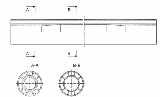
The component shown in Fig. 1.6 consists of two concentric pipes and longitudinal ribs distributed circumferentially evenly between them. Internal pipe has upsets at the ends.
Such a component can be produced at the Kamensk-Uralsky Metallurgical Works by extrusion process with different cross-section geometry and of different aluminum alloys, including a high strength aluminum alloy (group II, ISO 15546 [10]) used in production of aluminum drill pipes (ADP) of high dependability [9] . A technological possibility to produce the upsets at the both ends of internal pipe of such a multi-cell structure has occurred recently. The upset presence makes it possible to produce a conical thread at the both ends and have almost entire length of the pipe of lesser thickness. It makes it possible in turn to optimize the pipe body configuration in terms of stiffness to weight ratio. So, such a concentric
Fig. 1.6 – BADP pipe body possible to produce at Kamensk-Uralsky Metallurgical Works
pipe with upsets could be used in drilling pipe production, since it can be assembled with standard steel tool joints by means of conical thread connections and connected with other pipes to compose a DS (Fig. 1.7).
1.3.2. BADP advantages and disadvantages in ERD
Main advantages and disadvantages of an idea of buoyant aluminum drill pipe for ERD as compared with standard drill pipes are discussed below.
1.3.2.1 The advantages
Having steel tool joints at both ends, connected by means of conical thread connections, and provided that the annular space between the pipes is closed and has an air or a certain light-weight material inside, such a new type of drill pipe could have several essential advantages for usage in ERD over standard drill pipes.
Since a wellbore during drilling is filled up with a drilling fluid, interacting with it the drill pipe in question will have increased buoyancy (Fig. 1.7) and, hence, decreased weight in drilling fluid (or weight in mud). Such a buoyant aluminum drill pipe (BADP) used for drilling of an extended-reach well (ERW) will require less amount of torque and axial load to be moved in inclined or horizontal hole section. BADP could have greater stiffness than that of standard ADP at the same time having the equal or even less weight in drilling fluid. Having even lesser stiffness than steel drill pipes do, BADP could have greater the stiffness to weight ratio due to more than 3 times lesser the weight in mud.
Mentioned advantages give BADP the potential to solve two essential challenges of ERD:
1. High torque and drag that have to be overcome to move the DS through the long inclined hole section,
2. Buckling of compressed section of DS when axial load is applied to generate the weight on bit (WOB) during drilling or push the DS through the deviated hole section while lowering a DS during tripping operations. Buckling generates additional contact forces between DS and wellbore walls increasing friction.
Solving the problems noted above will permit to drill ERWs with longer horizontal hole sections and reach farther oil and gas reservoirs.
1.3.2.2 The disadvantages
The main disadvantages BADP could have are as follows:
1. Hydraulics limitation. To provide the construction with enough buoyancy it should have enough annular space inside the pipe wall. So, due to increased BADP wall thickness, as compared with standard drill pipes, and, consequently, decreased area of the drilling fluid circulation channel, a pressure loss in the well will increase and more powerful drilling pump will be required. Decreased annulus area will require higher dynamic pressure during the circulation necessary at the bottomhole to pump the drilling fluid with cuttings through the annulus up to the surface. Thus, the bottomhole pressure will be also increased. That is negative, because a risk of formation contamination, drilling fluid loss and problems concerned also increases in this case. Reducing the radial clearance between two concentric pipes in BADP, thereby reducing the BADP wall thickness, will solve the problem, but reduced buoyancy will increase the weight.
A trade-off between buoyancy and drilling fluid transmission capacity should be found for each configuration of BADP. It is worth to note, that when the last world record wells of 11-12 km length were drilled with standard steel pipe (having better hydraulic efficiency), most powerful drilling pumps in the industry were used [4], [5]. So, hydraulics limit can be of primary concern in case of BADP usage in wells of standard diameters and more than 12 km length.
2. Aluminum alloys have three times lower the modulus of elasticity the steel used in drill pipe production has. That will make aluminum pipes less stiffer, and less axial load can be applied to aluminum pipe before buckling.
So, the WOB can be limited and measures increasing buckling strength should be analyzed and integrated in BADP design.
3. High stress concentrations could be caused by pressure exerting inside and outside the pipe of multi-cell configuration. The sum of hydrostatic and hydrodynamic pressures is supposed to cause higher stresses in BADP, than the same loading conditions will do in the case with standard solid-walled drill pipe.
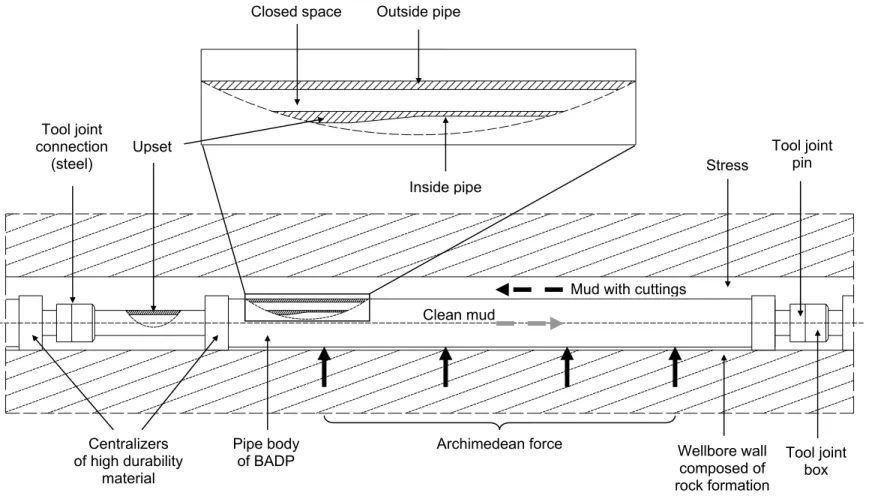
Closed space Outside pipe
Stress
Tool joint pin
Mud with cuttings Upset Centralizers of high durability material Tool joint connection (steel)
Archimedean force Wellbore wall
composed of rock formation Pipe body of BADP Inside pipe Clean mud Tool joint box
Due to presence of cavities and ribs inside BADP walls some parts of material under pressure will work in bending and inherent hoop stress concentrations should occur. Hydrostatic pressure of the drilling fluid column will add to the issue with the well depth increase. The issue is not critical for standard solid-walled drill pipes, where differential pressure is usually analyzed.
Increased thickness or greater number of ribs could be used in BADP to resist pressure, but at the same time a weight of BADP will increase. Thus, the optimal configuration of BADP cross-section, which will have a uniform stress distribution under pressure, should be found.
The limitations mentioned above could limit the possible horizontal displacement of an ERW drilled with use of BADP and overall BADP efficiency in drilling farther than is possible using conventional drill pipe technology. Once these problems are solved it will be known more about BADP feasibility for ERD.
1.4
Outline of the Thesis
Present work concerns the developing of an innovative type of drill pipe with mechanical properties optimized for ERD conditions and enabling greater horizontal displacement. As mentioned before, the main limiters of conventional drill pipe technology (standard steel drill pipe) performance in ERD are high torque and drag, buckling and hole cleaning from cuttings in the slant or horizontal wellbore sections.
So, a drill pipe with high resistance to buckling, light weight in drilling mud and which help to clean a hole from cuttings is assumed to be ideal for ERD. Buoyant Aluminum Drill Pipe (BADP), shown in Fig. 1.6, buoyant in drilling mud due to presence of air or light weight material inside the pipe body walls, having an effective system allowing recirculation of settled cuttings and disintegration of cuttings bed, due to mechanical turbulization of drilling mud flow and a scooping effect, correspondingly (such a system consists of centralizers with spiral blades placed on BADP pipe body which are not shown in Fig. 1.6, its principle is described in [10] and discussed in this thesis) and with a high buckling resistance (due to greater stiffness to weight ratio) could be such an ideal drill pipe for ERD. However, increased volume of new pipe construction, due to enhanced wall thickness, could limit hydraulics. So, feasibility study should be carried out to put the new structure into limiters like mechanics, hydraulics, industry standards and manufacturability.
One of the main goals at this phase of engineering design is to create a tool enabling analysis of a lot of pipe body cross-section configurations in a short period of time and involving all the necessary theories and models that describe the drill pipe mechanical behavior and elements interacting with it during drilling. Such a tool is developed and described in Chapter 5, theories and models it implements are described in Chapter 3.
Fig. 1.6 - Conceptual design of BADP and directions of drilling mud flows
As noted before and shown in Fig. 1.6, BADP has a cavity inside the pipe body wall, filled with a light material or a gas that makes it buoyant. Air has a great advantage to decrease the floating weight of drill pipes, but its use can be problematic under high mud pressure that loads both the internal and external pipe walls. Light weight materials, like composites with glass bubbles inside, could improve BADP properties under high pressure. So, strength/weight trade-offs should be extensively studied. This question is extensively discussed in Chapter 3.
First optimal solutions for BADP pipe body geometry were found for standard well diameters. They do not have big advantage over conventional technologies in such conditions, but the solution found feasible to enable 20 km length horizontal well with diameter bigger than standard one, makes evident the potential of BADP to drill farther, than it is possible using standard drill pipes. Such feasible solutions are presented in Chapter 5. BADP, as mentioned previously, is stiffer than standard drill pipes, so it will cause higher bending stresses in a well and need a TJ connection with fatigue strength higher than 50 MPa (fatigue limit for the standard TJ connection on 147 mm ADP [11]). Mechanical properties of TJ connection including fatigue, torque resistance and tensile strength are discussed in Chapter 6.
The objective of the present work is to design a drill pipe construction enabling to increase a horizontal displacement of an ERW and reliability of ERD. The design process will be based on:
- study and modeling of drill pipe working conditions in ERD;
- definition of the system parameters, that limit horizontal displacement of an ERW;
- developing of feasibility criteria for drill pipe in ERD and examination of innovative BADP configurations for such a criteria compliance.
CHAPTER 2
MATERIALS
2.1 Design characteristics for drill pipes material selection
A variety of drillstring operations under various loading conditions and high requirements for the drillstring strength, safety and service life suggest a comprehensive approach to the materials selection for drill pipe production. The selection of physical and mechanical properties of drill pipe materials depends on specific geological and technical drilling conditions. Some properties, for instance, pipe material density affects technical and economic characteristics of drilling operations. Other properties, for instance, the material modulus of elasticity affects the drillstring stress-strain state, etc.
In order to evaluate the performance of materials used in drill pipe production the effect of the main physical and mechanical properties on the drillstring service conditions was considered. Tab. 2.1 indicates the corresponding data [12].
The steel with properties corresponding to those given in the table above is commonly used in Steel Tool Joints (STJ) production both in cases with standard Aluminum Drill Pipes (ADP) and Steel Drill Pipes (SDP). This steel is referred to as AISI 4145 H steel. Its properties will be used in the STJ material model description in the BADP design process.
Material Density [kg/m3] Young’s modulus [MPa] Shear modulus [MPa] Poison ratio Aluminum alloys 2780 71000 27000 0.3 Titanium alloys 4540 110000 42000 0.28 Steel 7850 210000 79000 0.27
Tab. 2.1 – Main physical and mechanical properties of materials available for drill pipes production (T=20°C)
2.1.1 Specific strength
The drillstring weight is one of the most important characteristics that affect well drilling performance and economy. The drillstring weight with the same drill rig installed capacity determines the drillstring tripping time, while the percentage of the tripping time in total rig time increases considerably with well depth increasing. The drillstring weight depends on the density of drill pipes material, pipe geometry and wellbore length. The drilling mud makes the drillstring somewhat lighter depending on the ratio of densities of drill pipes material and circulating fluid.
When deciding whether the material is promising as drill pipe material it is convenient to use the notion of specific strength of the material L to be defined as the ratio between the yield stress σY and the specific weight of the material γDP:
DP Y L
γ
σ
= (2.1)Clearly the specific strength of the material has the dimensions of length and as applied to the drillstring, it defines the ultimate length of the single-size drillstring suspension in the air, while the stress at the point of drillstring holding reaches the yield stress of the material. In view of the drillstring weight reduction by the circulating fluid of γf specific weight and the safety factor k, the specific strength
equation, Eq. 2.1, may be written as:
) ( DP f Y k L
γ
γ
σ
− = (2.2)To evaluate the possible length of single-size drillstring suspended in borehole filled with circulating fluid of various densities the graph shown in Fig. 2.1 can be used [6]. The shaded areas in the graph indicate the permissible suspension length of the single-size drillstring of aluminum alloys, titanium alloys and steels correspondingly. The length was calculated with regard to possible changing of the yield stress of the given material and the
density of circulating fluid γf in the range of
1000-2000 kg/m3.
Fig. 2.1 shows that single-size drillstring of aluminum drill pipes (ADP) is the longest. In spite of high absolute magnitudes of the yield stress ranging within 490-1080 МPа, the drillstring of titanium alloy pipes is of second length range as compared with the drillstring of ADP. The suspension length of drill pipes made of the S-class high-strength steel (SDP) provides on the average only 30% of the parameter characteristic of ADP. Fig. 2.1 clearly specified the effect of the circulating fluid density on the permissible suspension length. For instance, if the density of circulating fluid γfincreases from
1000 to 2000 kg/m3, the suspension would
be 2.3 times longer with ADP, while with
Fig. 2.1 – The possible single-size drillstring suspension
SDP the increase in density does not have a pronounced effect.
2.1.2. Elastic properties
The most important properties of drill pipe material are the Young’s modulus E and the shear modulus G that markedly affect the drillstring stress-strain state. Some critical features of drillstring operation that are directly connected with the mentioned properties are considered hereafter.
The drillstring rotation exerts the alternate bending stress that reaches high levels during directional and horizontal drilling. The variable component of bending stress within the pipe body may be defined from equation:
2 0 2 8 ) ( L d D Ed ab − =
π
σ
(2.3)where: d = drill pipe outside diameter; D = wellbore diameter;
L0 = length of half-wave of the drillstring bent axis.
The pipes of various materials but of the same geometry have L0 difference ranging
within 5 to 7% [6]. Therefore, it may be assumed with a small error that under otherwise equal conditions the alternate bending stress in drill pipes is proportional to the Young’s modulus of the material and ЕА:ЕТ:ЕС = 1:1.55:2.96 for aluminum,
titanium and steel drill pipes correspondingly. It means that the bending stress in ADP will be almost three times smaller than in SDP of the same geometry. Fig. 2.2
Fig. 2.2 – Bending stresses in drill pipes of different material depend on the drill
0.3 0.42 0.54 0.66
DS/wellbore diameters ratio
Bending stre ss [MPa] 30 25 20 15 10 5 0
shows the bending stress calculated by Eq. 2.3 for steel, aluminum alloy and titanium drill pipes depending on the wellbore diameter to illustrate the important benefits of ADP application against steel drill pipes.
The value of Young’s modulus of the drill pipe material is critical also during the drillstring passage through the inclined borehole sections. The smaller is the absolute value E
,
the better the drillstring fits in the deviated borehole and the smaller is the exerted bending stress, which can be approximately defined by equation [6]:R dE b = 2
σ
(2.4)where: R is the radius of hole curvature.
Therefore, it is recommended to drill the greatly inclined boreholes using pipe material of smaller Young’s modulus.
2.1.3. Drillstring handling
The landing of heavy drillstring on the elevator or in the rotary slips during tripping operations exerts tensile dynamic stress, which can be calculated from the equation: g E DP a d
γ
ν
σ
= (2.5)where:
ν
a is the lowering/hoisting speed of the drillstring.Thus, under otherwise equal conditions the dynamic stress exerted during the round trip operations is proportional to the magnitude EγDP/g of the material and
the magnitudes ratio for aluminum, titanium and steel drill pipes will be 1:1.6:2.9 correspondingly.
The conclusion from the above simple analysis was that the physical properties of aluminum alloys provide important advantages in drillstring design.
2.2 ISO 15546, group II Aluminum alloy
Aluminum alloy 1953T1 (in terms of Russian industry classification) satisfying the requirements for ISO 15546, group II Aluminum alloy has been proposed by the ENI S.p.A to be used in the Buoyant Aluminum Drill Pipe (BADP) design procedures. Its high strength to weight ratio was highly evaluated by the engineers from the ENI E&P division.
Mechanical properties of the aluminum alloy in discussion were extensively tested at the laboratory of the D.I.M.N.P. (Mechanical Department) of the University of Pisa. Static and fatigue properties were evaluated, to provide a background for further investigation of the ADP and BADP mechanical behavior in accordance with
the goals of the joint-research project described earlier. Test results were then published in the Italian conference AIAS 2005 [13].
The present paragraph represents only the static tensile test on small specimens extracted from standard Aluminum Drill Pipe (ADP). Tensile test was carried out to provide tensile stress-strain curves useful to build the model of the material elastoplastic behavior for the finite element analysis of the BADP pipe body and pipe body to steel TJ connection stress-strain state.
2.2.1 Chemical structure analysis
The chemical composition of the alloy in discussion is reported in Tab. 2.1.
In agreement with standard specification ISO 15546 [11], the material group II aluminum alloy is an Al-Zn-Mg system. According to the (American) Aluminum Association (AA), or the European Aluminum Association (EAA) specifications, the AA 7014 alloy is chemically very similar to the present alloy [14].
Al wt% Mg wt% Zn wt% Cu wt% Mn wt% Cr wt% Ti wt% Zr wt% Fe wt% Si wt% Oth. wt% Bal. 2.4-3.0 5.5-6.0 0.4-0.8 0.1-0.3 0.1-0.2 ≤0.1 ≤0.1 ≤0.2 ≤0.2 ≤0.1 Tab. 2.1 – Chemical composition of ISO 15546, group II aluminum alloy [10]
It is well known that Zn aluminum alloys are high strength. In particular AA 7075 alloy has the strongest static tensile strength among all commercial aluminum alloys. The alloy in discussion is very similar to AA 7075 (AA 7175 as well). The main discrepancy in composition is lower Cu, which is below 1% in the present alloy while up to 2% in AA 7075.
2.2.2 Static tensile test results
Fig. 2.1 – Micrograph of the aluminum alloy structure. Specimen is extracted from ADP in the direction longitudinal to the extrusion (axial direction).
Due to the extrusion and following tension during the aluminum pipe body production, the aluminum alloy structure has clearly distorted grains in longitudinal direction (parallel to the pipe axis). A micrograph of the alloy structure shown in Fig. 2.1.
All the material specimens used in laboratory tests were extracted from ADP upset in the direction parallel to the pipe axis to preserve the grain direction. Fig. 2.2. shows the scheme of specimens extraction.
Aluminum alloy specimen
Fig.2.2 – Plain and notched specimens extracted from ADP upset ADP pipe body
Box-side upset
Tensile test was performed to evaluate aluminum alloy static properties. Fig. 2.3 shows engineering and true stress–strain curves.
0.4 0.3 0.2
ε [1]
0.1 0 700 600 500 400 300 200 100 0 Engineering curve Yield limitUltimate tensile strength Engineering final fracture True curve
True final fracture
σ
[MPa]
Fig. 2.3 – Aluminum alloy tensile test curves: Engineering stress-strain curve and True stress-strain curve
Tab. 2.2 represents main static test results.
E
[MPa] [MPa]
SY,0.2
[MPa]SU
[MPa]Ep
[%]εf
72964 494 544 1800 12.5Tab. 2.2 – Main static test results: E, modulus of elasticity, SY,0.2, yield strength,
S
U, ultimate strength, Ep, after yielding tangent modulus, εf, engineering fracturestrain.
The requirements to the group II aluminum alloy static properties given in the Standard ISO 15546 [11]: SY,0.2 = 480 MPa, SU = 550 MPa, εf ≥ 7% are in good agreement with results experimentally obtained and here reported.
It is remarkable to show the quite brittle behavior of the aluminum alloy specimens in comparison with the specimens of the Tool Joint steel, in terms of final necking and fracture surface morphology, Fig. 2.4.
Fig. 2.4 - Tensile test fracture surfaces, comparison between ADP and STJ materials
In the aluminum specimen the necking is less evident and the final fracture is basically brittle, fracturing in shear condition. On the contrary for the steel the surface is more similar to ductile fracture, with more evident necking and perpendicular to axis dimpled surface [15].
2.2.3 Material yield strength dependency on temperature
Implementing a static strength design of DS composed of DP of 1953T1 aluminum alloy, the dependency of the alloy on temperature should be taken into account.
Fig. 2.5 shows dependency of the yield strength of the two loosely used alloys in ADP production, D16T and 1953T1, on the temperature under 500 hours exposure
The gr [12]
aph analysis makes it evident that usage of the alloy in high temperature
Yield stre ngth [MPa] 550 450 350 25 150 50 0 20 40 60 80 100 120 140 160
Fig. 2.5 – 1953T1 aluminum alloys yield strength dependency on temperature under 500 hours exposure
T [0C]
conditions is inexpediently. More over, taking into account that after 100 oC the alloy yield strength decreases more rapidly, this temperature limit will define maximum depth of design well in the BADP optimization calculation. Considering the temperature gradient, typical for Siberian oilfields, equal to 3 oC per 100 m (see Tab. 3.1 in Chapter 3), at the vertical depth of 3000 m the temperature will increased up to 100 oC. If the well depths do not exceed 3000 m, the alloy yield
CHAPTER 3
DRILLSTRING THEORY
This chapter outlines configuration of a standard Aluminum Drill Pipe (ADP) and the loads on pipe occurring during drilling and operations concerned. A typical extension of drillstring (DS) theory is given in the chapter. The theoretical models described hereafter determinate loads on pipe as a function of the well length and vertical depth and are all presented by explicit equations. Theoretical models described in this chapter will be used in the BADP parametric analysis.
3.1 Drill pipe loading conditions
All the DS components described earlier are continually subjected to loads different in character:
- axial tensile load from deadweight and pressure drop on bit and downhole motor;
- axial compressive load from deadweight; - bending forces occurred during DS rotation; - torsional forces needed for the bit rotation;
- forces caused by the downhole motor reactive moment; - forces caused by the drilling mud circulation pressure;
- friction forces occurred between the DS and wellbore surfaces; - axial loads occurred when the DS drag or slacking-off take place; - inertia forces during the tripping operations;
- bending forces occurred in deviated hole sections;
- bending forces occurred in an offshore drilling when the drill ship heaving takes place;
- forces caused by the DS vibration, including longitudinal, torsional and bending vibration due to the rotation of not balanced DS, uneven running of the downhole motor, or heterogeneity of the drilled formations.
A character of loads on DS changes both in length and in time. Therefore, it is practically useful to carry out stress analysis only for critical loading conditions could be in particular cases of drilling that can limit a trouble-free operation of a DS. To such a particular loading condition in ERD one can refer high torque and drag occurred in the long horizontal hole section to be overcome to move a DS. To a special feature of DS operation one can also refer the following: like a long thin rod subjected to axial, lateral forces and torsional moment, it can buckle.
Rotation of a buckled pipe causes cyclic bending with eventually failure and often a one-side abrasive wear of the drill pipe tool joints.
b c d a
Fig. 3.1 – Standard aluminum drill pipe:
a – steel TJ pin, b – pipe body, c – internal upset, d – aluminum pipe to steel TJ connection, e – steel TJ box
Analyzing the ADP construction shown in Fig. 3.1, one can specify several critical sections in which maximum stresses are caused by different loads:
The pipe body (Fig. 3.1, b) is the weakest DP section under the static loading takes place during drilling and tripping operations. The loads concerned are torque and internal hydraulic pressure during drilling and tension during the DS hoisting. These loads are maximal in the upper part of DS.
Pipe body buckles if axial pushing load exceeds the critical buckling load. In ERD buckling often occurs in inclined or horizontal hole section where drill collar connects with the compressed section of DS that usually is of much lower stiffness. A tension is critical for the pipe body during the tripping operations.
During the tripping the upset (Fig. 3.1, c) is fixed in drill pipe slips and is subjected to circumferential compressive load. Extended length, thicker wall slip section is designed true for increased slip crushing capacity. The length is standard and is fitted to the standard length of drilling slips. The lengthier slips are used, the less is the stress in the upset.
The aluminum pipe to steel TJ permanent connection (ADP-STJ) (Fig. 3.1, d) is the weakest section in cyclic bending loading due to fretting issue or stress concentrator presence. Hence the fatigue strength is of a primary concern in the connection design process. The ADP-STJ, as well as the box to pin TJ (STJ-STJ) connection are designed to have 15% greater the static strength than those for the pipe body [16].
3.2 Theoretical models for drillstring design in horizontal drilling
Requirements to the design of extended-reach DS including ADPs are in accordance with those given in [16]. The DS design process should include the following steps:1. Calculation of buckling critical force for the DS compressed section;
2. Calculation of the torque and drag occurred in the well when DS is moved during various drilling operations (drilling, tripping);
To carry out stress analysis of a critical pipe section all the loads on pipe should be estimated. In the present thesis for the drill pipe (DP) body stress analysis only the static loads on pipe that can limit possible horizontal reach of drilling are considered. All these loads are functionally dependent on the well length or depth and DP configuration.
As the DS is a part of the drilling mud circulation system and its hollow structure creates the hydraulic channel for the drilling mud flow, pipes geometry should provide optimal hydraulics. Determination of the drilling mud pressure in all parts of the system as well as checking of the limits concerned, like formations integrity, the minimum mud flow velocity, necessary to efficiently clean the cuttings out from the long deviated hole section, are all of the primary concern in high-pressure extended-reach wells.
All the necessary theoretical models are presented hereafter.
3.2.1 Drillstring buckling in long horizontal wells 3.2.1.1 Sinusoidal buckling
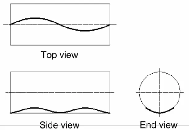
It is well known that due to gravity a DS in a horizontal hole section generally lies straightly on the lower side of wellbore before pipe is buckled. When an axial compressive force on DS exceeds certain limit load, DPs begin to buckle sinusoidally.
Fig. 3.4 shows a scheme of sinusoidally buckled DS. Buckled, it continues to lie on
Certain contact forces develop between the DP and wellbo the lower wall of the wellbore, but its shape is similar to a snake.
re walls due to
p
Fig. 3.4 – Postbuckled configuration of pipe in horizontal hole: the sinusoidal shape End view
Side view Top view
deformed shape. There are some equations to know contact forces between pipes and walls, but for drilling needs is much more interesting evaluate the critical force. Considering the energy point of view, under buckling condition three different kinds of energy are implicated:
- work done by external axial compressive load W1;
- work done by proper weight (gravity effect) of drill string W2.
Up = W1 + W2
(3.1)rgy increment will be equal to the work done by the axial lo Potential energy has to be equal to total work of external forces:
So, bending ene ad and
gravity. Integrating and resolving, looking for minimum energy of deformation, for an inclined wellbore [17]: 2 cos sin 4wEJ
θ
_sin sin _θ
w L r Fcr = + cr (3.2) 4 / 1 4 sin _ sin ⎟⎟⎠ ⎞ ⎜ ⎜ ⎝ ⎛ =θ
π
w rEJ Lcr (3.3)where:
Fcr_sin = the sinusoidal buckling critical load [N];
tal tract [deg];
sin the first buckling order
w
h unit in mud [N/m];bore and drill pipe
In case of pure ho
E
= the Young’s modulus [MPa];J
= the inertia moment [m4];θ
= the slant angle of horizonLcr_
= the minimum critical length linked with (half sine wave) [m];= the weight per lengt
r
= the radial clearance between well(considering maximum external diameter of DP) [m]. rizontal drilling θ = π/2. r wEJ 4 Fcr sin_ = (3.4) 3.2.1.2 Helical buckling
creases further, over sinusoidal load, the amplitude of
on As the compressive load in
sinusoidal buckle increases, and portions of drill string lose contact with borehole and rise toward the upper wall of the hole. Eventually, load reaches another critical value at which drill string forms a helix that is in full contact with walls of the hole. Drill string becomes helically buckled. Fig. 3.5 shows the helically deformed DS. As seen before for sinusoidal buckling, potential energy linked to the deformati will be equal to the work done by the axial compressive load plus the work done by proper weight. Bending energy increment for helical buckling will be greater than
Fig. 3.5 – Postbuckled co of pipe in horizon e lical shape Top view
Side view End view
he tal hole: th nfiguration
that for sinusoidal buckling due to severe helical bending. Most of the researchers used the hypothesis of constant load during the deformation instead of considering a changeable load. In reality, load increases during the application because of effect of the frictional drag and the contact forces.
If the drill string is not rotated, the buckling is not harmful for the DP and it only increases drag in the wellbore. The axial pipe displacement through the hole is yet
uckling occurs.
possible. When helical buckling occurs a rapid increase of torque and drag occur and the DS displacement becomes impossible [18]. The drillstring rotation practically does not affect the value of sinusoidal buckling critical force, Fcr_sin [19], but if the buckling takes place, the applied torque tends to create a helical deformation [20]. More over, the one-side abrasion of TJ and pipe body, and a cyclic bending occur. Thus, with the pipe rotated it is a good practice not to allow both the forms of buckling.
Eqs. 3.5 and 3.6 are conventional formulas considering the average compressive axial load when the helical b
2 cos sin 8 _ _
θ
θ
cr hel e e hel cr w L EJ w F = + r (3.5) 4 / 1 4 _ sin 8 ⎟ ⎟ ⎠ ⎞ ⎜ ⎜ ⎝ ⎛ =θ
π
e hel cr w rEJ L (3.6)For pure horizontal hole section, where θ = π/2, the helical buckling critical force,
,
can be calculated with Eq. 3.7.hel cr _