__
Titolo
Summary Tables for European Energy Technology Road Map
Descrittori
Tlpologia del documento: Technical report Collocazione contrattuale :
Argomenti trattati: Energy Technology Road Map
Sommario
The Strateg
i
e
energy
teehnology Pian (SET
-
Pian)
ìs
tl,e
technology
pillar
of
the EU
's
energy and
clìmate
polìcy_
The
objective
is to dr
ive
the
improvement and development of
tlìe technologies
necessary to
adapt the current energy system
into a
more sustalnabie
,
competitive
and
secure one
.
The aim
is to
reduce carbon dìoxide (C0
2)emissions by at
least 85
%
by
2050
compared
to
tlle
1990
levels.
It responds to
the
challenge
01'
accelerating the
developme
n
t
of
iow-carbon
technalogies.
l
ead
ing to their widespread
market
take-
up
_
This
doeurnent
summarizes the
principa
ì
character
ì
stics of each energy
tecll
no!ogy
i
nvolved
in
tlle
SET-Plan
in
arder
to
identify
the
state
of the
art and the further
potential
improvements
at
medium
and
long-term
of both technology and materials
. Th
e
focus of this
report is
to provìde
a generai
framework
far
a comparative assessment of 1he
impacts and the su
stai
nability
performance of
r
enewable
,
fossi!. and
nuclem
techno
logies.
Report
Note
Copia n. In carico a:1
-2-1·
~~~~~~
~~
~~~~~~~~
~
~~~~~~~~~r-~
-~-;-.=-1:~~"~:-
-
-
..
__
.
...
~
=
+
r-
_
....
.
.._
.
..
-
...
-
_
.
.
_
~
..
_-
.._ _
-
__ __
-
.
...-.
..
-
..
_
.
.
...
-
_
.
.
.
..
-
.
. .
_
.
.
..
-
..
_-
~
..
..
-
_
..
-
..
_
.
.
..
-
-
_.~__-
-
.._
-
...
~~
.
_
-~-~~-+j'-_-~=_-=-~
-
-.
_ -
-
._--
~~--
-_._
-
....
_
_
..
-;
.
--I...!
1
I l'Ii OMEi
I
~-~
r-E-M~~-SION~- ~-~
A
~ t-
-
...._-...-;-::-:--:-·
-
-·---1
;H-:Hf-~_
.
~_-·-e_-~--,~i-':Ci+-
k
~-~-
G..
-+k-+r~
,
-ffT,:r : : - , - -~Z;n~
TABLE OF CONTENTS
Introduction
3
Wind Power Generation
5
Solar Photovoltaic Electricity Generation
7
Concentrate Solar Power Generation (CSP)
9
Hydropower
12
Geothermal Energy
14
Marine Energy
16
Carbon Capture and Storage in Power Generation
21
Advanced Fossil Power Generation
24
Nuclear Fission
27
Nuclear Fusion
29
Bioenergy Power and Heat Generation
31
Biofuel for the Transport Sector
34
Hydrogen Fuel Cells Technology
35
Electricity Storage in Power Sector
38
Smart Grid
42
Cogeneration or Combined Heat and Power (CHP)
44
Heat Pumps
46
Conclusions
48
Introduction
The European Union (EU) is tackling climate change, energy supply security and economic
competitiveness through the transformation of the energy system, with far-reaching implications
on how we source and produce our energy, how we transport and trade it, and how we use it.
The aim is to reduce carbon dioxide (CO
2) emissions by at least 85 % by 2050 compared to the
1990 levels. There is no single energy technology that alone can sustain this transformation.
Either the energy sources are not sufficiently abundant or they have drawbacks in terms of
sustainability or security of supply. In other cases the technologies proposed are not yet
competitive as compared to technologies using fossil fuels. Therefore, a broad portfolio of
low-car-bon technologies is required for coping with future uncertainty.
Since 2008, the EU implements the Strategic Energy Technology Plan (SET-Plan) with the aim
to:
a) accelerate energy technology development, technology transfer and up-take;
b) maintain EU industrial leadership on low-carbon energy technologies;
c) foster science for transforming energy technologies to achieve the 2020 energy and
climate change goals; and
d) contribute to the worldwide transition to a low-carbon economy .
The intent of this report is to set a general framework of European energy technologies as the
basis for further comparative assessment of the impacts and the sustainability performance of
renewable, fossil, and nuclear technologies. Although a wide range of technologies and
methods exist to improve energy performance, supply renewable energy sources and reduce
emissions, only some of these will be summarized herein. Much of the data are been taken up
from two main documents: 2013 Technology Map and the Materials Roadmap Enabling Low
Carbon Energy Technologies. The first provides up-to-date information about the current
European energy technology portfolio and the potential improvement that could be carried out
by R&D; the second one complements and expands the technology roadmaps developed in the
context of the SET-Plan as the basis for its implementation.
In order to provide a most detailed framework, the tables presented below have been divided in
two main parts. The upper part composed of four fields: Technology, Components, State of Art
and Research Areas and the bottom part composed of two fields Materials Road Map and
Market. It has not been possible to bring up the Components field in all of the tables owing the
complexity of some technologies. Furthermore in some of the tables below, the Materials Road
Map field will be absent, because some technologies were not mentioned in the Materials
Roadmap Enabling Low Carbon Energy Technologies.
The emphasis will be given on the following technologies:
1. Wind Power Generation;
2. Solar Photovoltaic Electricity Generation;
3. Concentrated Solar Power Generation;
4. Hydropower;
5. Geothermal Energy;
6. Marine Energy;
7. Carbon Capture and Storage in Power Generation;
8. Advanced Fossil Power Generation;
9. Nuclear Fission Power Generation;
10. Nuclear Fusion Power Generation;
11. Bioenergy- Power and Heat Generation;
12. Biofuels for the Transport Sector;
13. Hydrogen and Fuel Cells;
14. Electricity Storage in the Power Sector;
15. Smart Grid;
16. Cogeneration or Combined heat and Power
17. Heat Pumps;
Table 1: Summary of Wind Power Generation Technology
Wind Power Generation
Technology Components State of Art Research Areas
HAWT (Horizontal Axis Turbines), are the most common turbine configuration used today, have the main rotor shaft and electrical generator at the top of a tower. Blades Composite Processing Technology: matrix composites (PMCs), ceramic matrix composites (CMCs) and metal matrix composites (MMCs) -Prepreg Technology(“pre impregnation”); -Infusion Technology. • Wood/laminates • Glass fibre laminates • Carbon fibre laminates • Polymer matrix composite (PMC) • Fiber reinforced plastic (FRP). Fibre-reinforced materials
• Materials modelling from micro-scale via phenomenological and subcomponent approach to full-scale modelling and extension; • Development of new/improved materials that combine high strength, stiffness, toughness and fatigue resistance for the production of very light blades;
• Development of recyclable materials for blades such as thermoplastics as well as natural fibres and biopolymers
Sandwich core materials
• Development of cost competitive, very lightweight core materials that perform at least as good as the currently used balsa wood and PVC foams and that can be recycled and produced in an environmental sustainable manner.
Adhesives and joining/bonding materials
• Development of adhesives and joining/bonding materials suited for the newly developed structural blade materials;
• Material characterization and modelling of adhesives and bonding materials to enable state of the art strength and fatigue analyses.
Coatings
• Development and testing of blade coatings to increase the biofouling erosion and UV light resistance, the self cleaning capability and the ice shedding efficiency;
• Development and testing of blade coatings to reduce the detectability of static or rotating wind turbines by radars (“stealth” materials). Tower • Still ; • Composite lattice (small turbines); • Pre stressed concrete;
Material developments and related joining technologies
• Development of high strength, heavy gauge, steels (thickness above 30 mm), with high toughness down to -50°C and withwell suited welding technology;
• Development of high efficient, in terms of productivity, welding techniques as submerged arc welding, laser welding and non-vacuum electron beam welding and hybrid-friction stir welding; • For onsite joining of parts the development of automatic or robotised gas metal arc welding procedures and the further development of bolted flange and friction connections;
• Application of coatings and development of new protection methods for towers and substructures to reduce erosion, oxidation and biofouling.
Concrete
• Development and application of drilled concrete monopiles and gravity based support structures for deep water applications.
Generator
• Induction generator
• Asynchronous generator
Permanent magnet materials
• Reduction of use and substitution of rare earth elements in permanent magnet generators;
• Development of stronger, lighter magnetswith improved key magnet parameters including intrinsic coercivity and remanence. High temperature superconducting materials
• Development of high temperature superconducting (HTS) generators for the application in large MW wind turbines;
• This includes the development of robust, reliable and low maintenance cryogenic techniques required for generator cooling; • Reduction in the price of superconductor wire.
Materials Road Map
The materials roadmap for wind energy proposes a comprehensive research and development programme on blade materials such as fibre reinforced and sandwich core materials as well as bonding and joining technologies to improve the mechanical properties at reduced specific weight, to improve rotor performance and lifetime by intelligent use of materials and to reduce the manufacturing cycle times and production cost of blades; the development of new coatings for improved erosion resistance, self-cleaning and UV protection; the development of steel with enhanced properties for tower and support structures and related welding techniques, of concrete for mono-piles and gravity-based structures for deep water applications; the improvement of foundry technologies for dross-free ductile iron with high as well as lightweight composite structure to replace cast iron components.
The roadmap focuses also on materials used in generator, power electronics and transmission (shaft, gears and bearing) with research efforts to substitute rare earth elements in permanent magnets and develop stronger, lighter magnets; to develop high temperature superconducting (HTS) generators, new materials for power electronics to increase the working limit of junction temperatures and metal alloys for transmission components to ensure an effective lifetime equal to the design lifetime. To scale-up the material development to industrial scales, the roadmap puts forward scale-up to 4 industrial manufacturing pilots to develop and produce concept blades at MW scale, to develop, manufacture and demonstrate lightweight (composite) hub, bedplate or generator gearbox housing as alternative for cast iron components, to design, produce and test large blades with a length of over 100 m that allows the economic design of >12 MW turbines as well as automated production techniques in a MW scale blade production line; up to 2 technology pilots to test gravity based support structure for large water depth and demonstrate a HTS generator at full scale. Finally the roadmap proposes the creation of Trans-European research field network facilitators to accelerate industrial development and the up-take of research results as well as a test rig for the testing of large (> 10MW) drive train units.
Market
There are two main market sectors: onshore and offshore wind. The differences include complexity of installation, working environment (saline and tougher at sea), and facility of access for installation and maintenance.
2013 was a record year for offshore installations, with 1,567 MW of new capacity grid connected. Offshore wind power installations represent over 14% of the annual EU wind energy market, up from 10% in 2012. A total of 117 GW is now installed in the European Union, a growth of 10% on the previous year and lower to the growth recorded in 2012 (+12% compared to 2011). Germany remains the EU country with the largest installed capacity, followed by Spain, the UK, Italy and France. Eleven other EU countries have over 1 GW of installed capacity: Austria, Belgium, Denmark, France, Greece, Ireland, The Netherlands, Poland, Portugal, Romania and Sweden.
Eight of the latter (Denmark, France, Germany, Italy, Portugal, Spain, Sweden, United Kingdom), have more than 4 GW of installed wind energy capacity.
Germany (34.3 GW) and Spain (23 GW) have the largest cumulative installed wind energy capacity in Europe. Together they represent 49% of total EU capacity. The UK, Italy and France follow with, respectively, 10.5 GW (9% of total EU capacity), 8.6 GW (7%) and 8.3 GW (7%). Amongst the newer Member States, Poland, with 3.4 GW (2.9%) of cumulative capacity, is now in the top 10, in front of the Netherlands (2.7 GW, 2%), and Romania is 11th with 2.6 GW (2%).
The wind power capacity installed by the end of 2013 would, in a normal wind year, produce 257 TWh of electricity, enough to cover 8% of the EU’s electricity consumption – up from 7% the year before.
Table 2: Summary of Solar Photovoltaic Electricity Generation Technology
Solar Photovoltaic Electricity Generation
Technology Components State of Art Research Areas
Thin-film technologies; Multi-junction and concentrator technologies Solar Panel Materials: inorganic or organic. Inorganic cells : silicon (Si) or non-Si material.
• Wafer-based cells or
• Thin-film cells. Wafer-based Si is divided into two different types:
• monocrystalline
• multicrystalline In 2012, more than 85 % of new PV systems were based on crystalline Si technology that is highly matured for a wide range of applications.
Primary research issues are: reducing the costs and increasing the performance of PV technologies, the energy and materials consumption in manufacturing and installation and the energy pay-back time of systems; increasing the lifetime of PV system components, substituting the use of scarce, hazardous, rare and expensive materials.
The main research areas are:
• Wafer-based crystalline silicon; in particular reducing the cell thickness and implementing advanced cells design, e.g. selective emitter, rear contact cells, etc.;
• Existing thin-film technologies; in particular emphasising the research activities on bottlenecks such as interfaces, intra-grain defects, interconnections, etc.;
• III-V multi-junction and concentrator technologies; in particular simplifying the multi-junctions formation, studying the mismatching and the tunnel layers.
• Advanced inorganic thin-film technologies with emphasis on high growth rates, stable and reliable materials as well as increased cell efficiency through innovative device structures; • Organic solar cells, based on polymers, molecules, dye sensitized and hybrid cells;
• Thermo-photovoltaics; • Novel PV-technologies; • Novel active layers;
• Tailoring the solar spectrum to boost existing cell technologies; in particular, the use of dots and nano-wires to improve photon conversion, i.e. down conversion, up conversion, multi-generation of excitons, and their implementation in conventional or advanced cells.
• Thermo-photovoltaic (TPV) cells and systems.
Materials Road Map
Materials are key enablers in all PV systems. Crystalline Si-based systems are expected to remain the dominant PV technology in the short-to-medium term.Most of the ‘novel’ approaches can be categorised as high-efficiency approaches, in both cases nanotechnology and nano-materials are expected to provide the necessary toolbox to bring about these effects.The materials roadmap for PV energy proposes a comprehensive research and development programme on the optimisation of materials usage through predictive modelling down to quantum devices at the nanoscale, the improvement of intrinsic performance and reduction in layer thickness of constituent materials for both inorganic and organic PV cells and modules, the development of alternative manufacturing processes for specific solar grade materials, the development of thinner, higher strength, conformal, lower cost glass as well as flexible, light weight, low cost, long lifetime and high barrier encapsulants and optical glues.
The roadmap focuses also on materials for light management (anti reflective, anti soiling, anti abrasion coatings, light trapping/guidance, spectral conversion and optical concentrators materials); the development of high through put, low cost manufacturing processes for film/layer deposition / thin film (epitaxial) growth; the development of materials for system-related devices such as inverters and trackers as well as the research into novel materials and processes. 3 manufacturing pilot projects on new solar grade materials, non vacuum deposition processes and PV high performance, thin, high strength glass; 1 field pilot to test new materials / device designs under real market conditions and to demonstrate the cost-effectiveness of combined High Concentrator PV and energy storage solutions for small-scale grid locations.
Market
Since 1990, annual global cell production has increased by three orders of magnitude from 46 MW to about 38 GW in 2012. this corresponds to a compound annual growth rate (CaGR) of about 36 % over the last 23 years. Statistically docu-mented cumulative installations worldwide accounted for 100 GW in 2012. the total installed capacity of PV systems in the eU in 2012 was 68.8 GWp, representing approxi-mately 8.5 % of the total eU electrical genera-tion capacity. the electricity generated by PV systems that year was approximately 65 tWh. the highest shares were reported for italy with 18.2 tWh and Germany 28.5 tWh, which cor-respond to 5.6 and 5.7 % of final electricity consumption, respectively. the annual installation of PV systems in 2012 in the eU was about 17.6 GWp and will like-ly remain in the first place of the ranking of newly built electricity generation capacity after it moved to this position in 2011. europe is cur-rently the largest market for PV systems with about 58 % of the annual worldwide installa-tions in 2012. in terms of solar cell production, europe has slipped behind China and taiwan to third place, capturing about 6.5 % of the world market; but it is still a world leader in PV tech-nology development.
Scenarios for the worldwide deployment of PV technology vary significantly between the 2010 IEA PV technology Roadmap scenario and the Greenpeace/European Renewable Energy Council (EREC) scenarios. The IEA scenarios range between 210 GW (298 tWh) by 2020 and 870 GW (1 247 tWh) by 2030, and the Greenpeace scenarios vary between 124 GW (158 tWh) by 2020 and 234 GW (341 tWh) by 2030 for the reference scenario, and 674 GW (878 tWh) by 2020 and 1764 GW (2 674 tWh) by 2030 for the advanced scenario.
Table 3: Summary of Solar Photovoltaic Concetrate SolarPower Generation Technology
Concentrate Solar Power Generation (CSP)
Technology Components State of Art Research Areas
Trough concentrators Linear Fresnel reflectors Central receivers (Solar towers) Dish systems The current CSP market is dominated by the parabolic trough technology. More than 80% of the CSP power plants in operation or under construction are based on this technology.
Collectors
Are usually subdivided into two types:
•Line-focusing systems : trak the sun position in one dimension (one-axis-tracking)
•Point-focusing systems: realize higher concentratin ratios than line-focusing systems, theis mirror track the sun position in two dimensions (two-axis-tracking)
The cost-competitiveness of CSP plants is a key barrier. There is a strong need for developing long term policy frameworks to foster and secure CSP technology developments and investments worldwide.
The industry is already focused on the R&D of the next stage of technology improvements, which shall have great impact on costs and efficiency of CSP plants. These improvements, which can be either technology specific or horizontal to most technologies, are centred on three main areas:
•Increase power generation efficiency, mainly through the rise of the operating temperature leading to higher turbine efficiency, but also through improvements in reflecting facets (Mirror’s capacity to reflect sun radiation) and receivers;
•Reduce solar field costs by minimizing costs and through design optimization that can lead to more cost effective solar fields deployment;
•Reduce internal resource consumption through reduction of needed water and auxiliary parasitic consumption (Plant operations require consumption of electricity, e.g. to pump fluids)
Key components to reduce the solar field cost are support structures, including foundations, mirrors and receivers. These costs will tend to decline over time as the overall volume increases.
For mirrors, cost reductions may be accomplished by moving from heavy silver-backed glass mirror reflectors to lightweight front-surface advanced reflectors (e.g. flexible aluminium sheets with a silver covering and silvered polymer thin film), silver-backed glass mirrors are highly specular, that is to say they concentrate the sun’s rays into a narrow cone to intersect the receiver. Any new reflector solutions need to also be highly specula.
The advantages of thin-film reflectors are that they are potentially less expensive, will be lighter in weight and have a higher reflectance. They can alsobe used as part of the support structure. However, their long-term performance needs to be proven. Ensuring that the surface is resistant to repeated washing will require attention. In addition to these new reflectors, there is also work underway to produce thinner, lighter glass mirrors.
Currently operating parabolic trough plants use a synthetic aromatic fluid (SAF) as heat transfer fluid. This fluid is organic (benzene)based and as such cannot reach temperatures above 400ºC with acceptable performance due toits decomposition at higher temperatures. This limited temperature range is capping overall steam cycle efficiency. To overcome this obstacle, developers are focusing on the development of alternative fluid technology, namely: molten salt, direct steam generation, nanotechnology improved fluids and alternative
inorganic fluids.
Receivers
They consist of an coated absorber tube and an encasing glass tube. The absorber is realized in the form of a coated steel tube surrounded by an evacuated glass tube which is highly
transmissive for the sun light due to an anti-reflexive Another concept is based on several parallel tubes forming a multi-tube receiver.
In the solar Tawer Plant the recivers use water/steam, air or molten salt to transport the heat, the upper working temperatures range from 250°C to 1000°C.
Support Structure
The metal support structure
For the support structures, developers are looking at reducing the amount of material and labour necessary to provide accurate optical performance (Flexing of the support structures in windy conditionscan have a negative impact on the concentration of sunlight on the receivers. ) and to meet the designed “survival wind speed”. Given that the support structure and foundation can cost twice as much as the mirrors themselves, improvements here are very important.
Thermal Storage
To date, this has been primarily for operational purposes, provi-ding 30 minutes to 1 hour of full-load storage.
Plants are now being designed for 6 to 7.5 hours of full-load storage, which is enough to allow operation well into the evening when peak demand can occur and tariffs are high. Storage media include:
•MoltenSalt
•Steam Accumulators
•Solid Ceramic Paricles
•High Temeperature Concrete
Today’s state-of-the-art thermal energy storage solution for CSP plants is a two-tank molten salt thermal energy storage system. The salt itself is the most expensive component and typically accounts for around half of the storage system cost, while the two tanks account for
around a quarter of the cost.
Improving the performance of the thermal energy system, its durability and increasing the storage temperature hot/cold differential will bring down costs.
For solar towers, increasing the hot temperature of the molten salt storage system should be possible (up to 650°C from around 560°C), but will require improvements in design and materials used. The development of heat transfer fluids that could support even higher temperatures would reduce storage costs even further and allow even higher efficiency, but it remains to be seen if this can be achieved atreasonable cost. If direct steam towers are developed, current storage solutions will need to be adapted, if the capacity factor is to be
increased and some schedulable generation made available.
Materials Road Map
The materials roadmap for CSP proposes a comprehensive research and development programme on low-cost, spectrally selective, high mechanically stable absorber materials suited also for higher temperatures; and the development of higher reflectance and/or specularity, cost competitive, sustainable reflector materials. The roadmap focuses as well on heat transfer media todevelop alternative syntheticfluids coupled with the improvement of molten salts and liquid metals to allow for higher temperatures, better heat transfer and better chemical stability; the development of more sustainable, reduced cost, corrosive-resistant structural materials such as steel, aluminium, fibre composites and the development of storage materials (heat storage materials and materials for thermo-chemical storage) to increase the performance and extendthe operating temperature up to 600°C. To scale-up the material development to industrial scales the roadmap foresees up to 5 industrial 6 pilot projects to manufacture absorber coatings, profiled multilayer tubes, high temperature synthetic heat transfer fluids, catalyst materials and heat exchangers of ceramics or alloys; up to 5 technology pilots to test and validate material performances under real market
conditions in the areas of storage technologies, new molten salt mixtures, porous ceramic or metal structures for central receivers, fluidised bed materials as well as piping and tank structures. The roadmap puts also forward 3 test facilities (for coating technology, high temperature research and for advanced composites) to bedeveloped in the framework of research infrastructure.
Market
At the end of beginning of May 2013, CSP plants with a cumulative capacity of about 2.05 GW were in commercial operation in Spain, repre-senting about 69 % of the worldwide capacity of 2.95 GW. together with those plants under construction and those already registered for the FIT, this should bring Spain’s CSP capacity to about 2.3 GW by the end of 2013. Projects that have applied for interconnection have, all together, a combined total capacity of 15 GW. This is in line with the SEII, which aims at a cumulative installed CSP capacity of 30 GW in Europe, out of which 19 GW would be in Spain (eStela, 2009). In the US, about 1.2 GW of CSP are currently under construction and another 4.2 GW in the development stage. More than 100 projects are currently in the planning phase, mainly in india, north Africa, Spain and the US. T he economic potential of CSP electricity in Europe is estimated to be around 1 500 TWh/year, mainly in Mediterranean countries (direct normal irradiance (dni) > 2 000 kWh/m2/year). Based on today’s technology, the installed capacities forecasted in the EU-27 under the SEII are 830 MW by 2010, 30 GW by 2020 and 60 GW by 2030. This represents respectively, up to 2030, 0.08 %, 2.4 % and 4.3 % of projected EU gross electricity consumption. Tese penetration targets do not account for imports of CSP electricity. According to the de SERTEC scenario, which assumes that a grid infrastructure will be built to connect Europe with North African Countries, CSP electricity imports of 60 TWh in 2020 and 230 TWh in 2030 could be realised.Tthe penetration of CSP electricity for 2030 under these scenarios would be 10 % of the EU gross electricity consumption.
Table 4: Summary of Hydropower Systems
Hydropower
Technology Components State of Art Research Areas
Hydropower plants (HPP) are very diverse in terms of size and type of plant, size and type of generating unit, the height of the water fall (“head”), their functions (electricity generation, capacity or multi-purpose) and sizes. Three functional categories: 1. Pumped hydropower storage (PHS); 2. Run-of-the-river (RoR) 3.Reservoir (or storage) HPP. Pumps
There are two main types of PHS facilities:
- Pure or off -stream PHS (which rely entirely on water that were previously pumped into an upper reservoir as the source of energy);
-Combined or pump -back PHS, which use both pumped water and natural stream flow water to generate power.
At state -of-the-art PHS system may achieve over 80%
efficiency.
Many EU countries have introduced large economic support programs, such as feed-in tariffs. Some of these systems include smaller-scale hydropower projects, but most exclude larger-scale hydropower projects. In this context, reservoir HPP and PSP could facilitate the expansion of variable renewables.
Many PSP projects are currently under development, in Europe. This includes modernization, upgrading or full redevelopment of 30- to 50-year-old PSP, and gradual expansion of recent plants.
Technological drivers include increasing the efficiency of generation equipment above the current 85–95 %, and enhancing the control capacity of pumps for PHS through variable speed. Three main drivers are pushing developments in this field: erection of new large hydropower plants abroad; rehabilitation and refurbishment of existing hydropower facilities in Europe; and the need for the storage capability that would allow the electricity system to accommodate additional renewable power from wind and other variable sources. average efficiency improvements that can be expected from refurbishment are of the order of 5 %.
Turbines
Small discharge, high-head installations are typically mountain-based dams and are equipped with Pelton turbines (impulse turbine). Large discharge, low-head installations are typically large RoR plants equipped with Kaplan turbines. intermediate flow rates and head heights are usually equipped with Francis turbines.( Kaplan and Francis turbines are reaction turbines).
R&D efforts address: load and fatigue analysis of turbine and generator components, in particular in a context of variable-speed and frequent stop–start operations; the integration of LHP with other renewable energies, for example through speed-adjustable generators; the development of hybrid systems, for example with wind, and minimising environmental impacts, for example turbine design with fewer blades and less clearance between the runner and housing to reduce injuries to and stress factors for fish, or oil-free Kaplan turbines to eliminate leak-related risks
Dams
In cases where dams have been originally built for other purposes, such as for flood control and for water storage for irrigation and urban use, a hydropower plant may be added with a capital cost as low as EUR 400/kW.
The impact of large hydroelectric facilities on the environment is often significant. Small installations, on the other hand, have minimal reservoir and civil construction work, so their environmental impact is
relatively low
Materials Road Map
Research in materials is focusing on cheaper alternatives to steel in some components and applications, such as fibreglass and special plastics. Developing more resistant materials to extend the lifetime of some components is also essential, for example steel alloys that are more resistant to turbine cavitation or high-voltage insulation systems able to sustain short-period operations to 180 ºC.
Market
The global installed hydropower capacity at the end of 2012 was 990 GW, with 30 GW added during that year (Ren21, 2013). With 3 700 TWh generated worldwide in 2012, hydropower accounts for an estimated 16.5 % of the global electricity generation and 79 % of all electricity from renewable resources. This share is expected to increase to around 19 % in 2020 and up to 21 % in 2030. In Europe, in 2012, the 106 GW of hydropower plants generated 330 TWh of electricity, or 44 % of that one from renewable energy sources (RES) - down from 65 % in 2007. this is 10 % of the total electricity production in the EU-27.The global potential has been estimated at 9 770 TWh, although the growth expected is more modest but still doubling current generation to 7 000 TWh by 2050, including a three- to five-fold of PHS capacity.Nevertheless, in terms of the share in gross electricity generation, and due to increasing electricity demand, a share decrease to 9.2 % in 2020 and further down to 8.8 % in 2030 is expected. This estimation is based on the fact that the most favourable sites are already being exploited across the EU, while due to environmental restrictions it’s unlikely that Europe could see much more expansion.
Table 5: Summary fo Geothermal Energy Systems
Geothermal Energy
Technology Components State of Art Research Areas
Geothermal energy can be used for a wide
range of applications fromstandard 12 kWt heat poump systems in residential buildings up to geothermal power plants with electric capacities of 100 MWe and more. The application depends on the system’s heat content and on the designated use of the geothermal source. Usually a minimum fluid temperature of 100°C is required.
There are three
types of
conventional geothermal power plants:
Direct Dry Steam Flash and Double Flash Cycle Binary Cycle Within each geothermal power plant category, the efficiency is mainly dependent upon the tempera-ture (80–300 °C) of the geothermal working fluid. Turbines Generators Transformers These components have the same characteristics of conventional energy
systems.
The conventional geothermal
power plants that are commercially available use hydrothermal resources that exist naturally in a particular location as their main supply of energy. There are three types of conventional geothermal power plants: dry steam, flash steam, and binary cycle and variations of them (e.g. combined-cycle or hybrid plants, combined heat and power). A typical geothermal dry steam/flash plant’s capacity is 50–60 MWe but up to 300 MWe plants (Hellisheidi, Iceland, 7 power units) have been commissioned and are currently in operation. Within each geothermal power plant category, the efficiency is mainly dependent upon the temperature (80–300 °C) of the geothermal working fluid.
Enhanced geothermal system
(EGS) development is seen as an alternative for energy production with high production potential compared to the conventional geothermal power plants that presently rely on scarce natural hydrothermal reservoirs. EGS can provide energy supply almost everywhere, since almost any site at a specific depth can be considered
a reservoir. in order to use this high potential, the EGS technology still needs to experience an intensified R&D phase in order to reach the stage of successful demonstration and commercially viable power plant by 2030
One of the main future challenges for the geo-thermal sector is the expansion of the EGS concept across the different regions and geological conditions of Europe. The construction of these types of novel power plants together with the development of more efficient binary cycle systems for low-temperature resources will preserve EU leadership in this area of geothermal technology and electricity production.
EGS development is seen as an alternative for energy production with high production potential compared to the conventional geothermal power plants that presently rely on scarce nat-ural hydrothermal reservoirs. EGS can provide energy supply almost everywhere, since almost any site at a specific depth can be considered a reservoir. in order to use this high potential,
the EGS technology still needs to experience an intensified R&D phase in order to reach the stage of successful demonstration and com-mercially viable power plant by 2030.
Several pilot projects are at the moment being conducted in australia, Europe, Japan and the US. The basic concept is to drill two wells into the HdR with limited permeabili-ty and fluid content at a depth of 5–10 km. High temperature reservoirs (200 °C) have though been found as shallow as 3 km, where the tem-perature gradient is high (70–90 °C/km).
The RD&dfor ORC should focus on the new heat-transfer fluids to improve efficiency, and improve the manufacturing capabilities to develop modularity benefits; the balance of the plant can be determined before construction. one advantage of the modular design is that the maintenance of individual units can be performed without taking the entire plant offline.
Materials Road Map
The R&D efforts proposed in the roadmap follow the different phases in the exploitation of a geothermal system. Focus is on innovative developments in accessing geothermal reservoir (including spallation drilling) that should worktowards an increase of economic depth.
An important contribution would come by researching lightweight materials for drill bits to extend their lifetime in highly abrasive and corrosive environments at high temperatures and developing site specific materials for proppants in conjunction with stimulation techniques. Improved monitoring of the downhole requires materials developments to make fibre optic cables and power electronics withstand the hostile environment they should operate in. When assessing the heat reservoir and the subsequent production phase, the accumulated deposition of material inside the pipes (scaling) and the extreme corrosion and temperature problems need to be tackled from a materials' perspective. This involves the development of corrosion-resistant materials for the pipes, equipped with protective outer coatings and insulation, and inner liners.
Novel polymeric, ceramic or metallic membranes to separate and re-inject gases would make the operation of a zero emission plant possible.The roadmap furthermore contains several proposals for research infrastructures in realistic laboratory or even in situ conditions. Materials standardisation would be the topic of one facility. In a large scale autoclave heat exchangers and working fluids can be tested, while research wells are needed to test the structural materials for the drilling tools and well components.
Market
According to the Commission's forecast, the capacity of the geothermal power sector is expected to reach 1 GW in 2020 and 1.3 GW in 2030. The estimated maximum potential for geothermal power in the EU-27 is up to 6 GW by 2020 and 8 GW by 2030. This represents about 1% and 1.3% of projected EU gross electricity consumption by 2020 and 2030 respectively. In the heating sector, the estimated maximum potential for geothermal is up to 40 GW by 2020 and 70 GW by 2030 (direct and indirect use combined).
Table 6: Summary of Marine Energy Systems
Marine Energy
Technology Components State of Art Research Areas
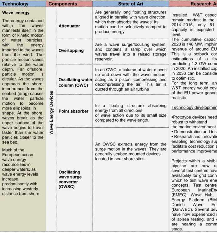
Wave energy
The energy contained within the waves manifests itself in the form of kinetic motion of water particles, with the energy imparted to the waves from the wind. The particle motion varies relative to the water depth. Far offshore, particle motion is circular. As the waves approach the shore, interference from the seabed (drag) causes the water particle motion to become more ellipsoidal in shape. At the shore, waves break as the upper surface of the wave begins to travel faster than the water particles closer to the sea bed. Much of the European ocean wave energy resource lies in deeper waters, as wave energy levels increase
predominantly with increasing westerly distance from shore.
W a v e En e rg y D e v ic e s Attenuator
Are generally long floating structures aligned in parallel with wave direction, which then absorbs the waves. Its motion can be selectively damped to produce energy
Installed W&T capacity is likely to remain modest in the short term, for 2014–2015, only 61 MW of new capacity is expected on the global level.
The cumulative capacity expected in 2020 is 140 MW, implying a total sector revenue of around EUR 500 million. This is a setback compared to the estimations of a few years ago predicting 1.3 GW cumulative capacity in 2020. An installed capacity of 15 GW in 2030 can be considered as realistic to optimistic.
For the long term, an estimate that W&T energy would cover roughly 5 % of the EU power generation in 2050 is realistic
Technology development:
•Prototype devices need to be very robust to withstand
the marine environment
• Demonstration and testing facilities • Research and innovation support and enabling technology support to facilitate cost reduction and performance improvement
Projects within a visible development pipeline are now underway, and several test centres have increased the availability for grid connected berths in which to test wave energy conversion concepts. Test centres include the European MarineEnergy Centre (EMEC), Wave Hub, Biscay Marine Energy Platform (BiMEP), and the Danish Wave Energy Centre (DanWEC). Several device developers have now experienced several months of at-sea testing, and certain devices are nearing a commercially viable stage.
Overtopping
Are a wave surge/focusing system, and contains a ramp over which waves travel into a raised storage reservoir.
Oscillating water column (OWC)
In an OWC, a column of water moves up and down with the wave motion, acting as a piston, compressing and decompressing the air. This air is ducted through an air turbine
Point absorber
Is a floating structure absorbing energy from all directions
of wave action due to its small size compared to the wavelength.
Oscillating wave surge converter (OWSC)
An OWSC extracts energy from the surge motion in the waves. They are generally seabed-mounted devices located in near shore sites.
Tidal Energy
Tidal device operation is ynonymous to that of a wind turbine, albeit operating within a different fluid medium.
There are three principal hydraulic mechanisms by which tidal currents operate: Tidal streaming, hydraulic current and resonant basins. Tidal streaming occurs as a result of the needfor continuity within a fluid flow: As water flows through a constriction, the flow is accelerated.
Hydraulic currents occur when two large bodies of water are connected, but are out of phase or have non-concurrent tidal ranges; the difference in water level in each body of water creates a pressure head, and the flow of water from one body of water into the other results.
The third mechanism, a resonant basin,
occurs when
constructive
interference between an incoming tidal wave and a reflected tidal wave generates a standing wave. T id a l D v ic e s Horizontal Turbine
Horizontal axis turbines utilise lift generated by blades to turn a rotor. Energy is extracted from the tidal flow and causes the rotation of a turbine mounted on a horizontal axis. The rotation is converted to electrical energy through use of a generator.
Tidal energy converters are now experiencing large scale demonstration and testing; some manufacturers have progressed beyond their original design concept and are looking into engineering solutions that will help to further reduce their cost of energy. Tidal energy converters can be classified into different “generations” of design as device developers and technologies
progress beyond the first prototype concept:
“First” generation technology has experienced significant levels of testing in ocean conditions, such as the horizontal axis type tidal turbines. As a general rule, first generation devices are fixed on sea bed mounted foundation structures with one or, possibly, two devices per foundation. “Second” generation technology offers novel ideas and solutions to moorings (for example buoyant turbines or foundations), allowing access to the faster flowing water higher in the water column and
reducing foundation costs. Second generation technologies may also achieve step change cost reductions by mounting multiple rotors on one foundation structure, maximising the energy output
per marine operation. Second generation platforms are already under development, although not necessarily by companies with existing first generation technology.
“Third” generation tidal devices consist of designs that radically change the way in which energy is harnessed by a given device, or allows access to many sites that were previously thought to be uneconomical. This may be a radical overhaul within the structure and PTO components of a device. Third generation technology may produce energy in tidal currents of much lower velocity than can be considered at present by moving the PTO through the current, rather than relying on an area
Vertical Turbine
Vertical axis turbines, similar to the above, utilise lift generated by blades to turn a rotor. Energy is extracted from the tidal flow and causes the rotation of a turbine mounted on a vertical axis. The
rotation is converted to electrical energy through use of a generator
Oscillating Hydrofoil
The oscillating hydrofoil device consists of a hydrofoil located at the end of a swing arm. Control systems alter the pitch of the foil to create either lift or downforce, moving the foil in an oscillatory motion. This motion can be used to pump hydraulic fluid through a motor. The rotational motion that results can be converted to electricity
though a generator
Enclosed Tips (Ducted)
Enclosed Tips (Ducted) devices are essentially contained
within a shrouded structure. The duct may be used to accelerate and concentrate the fluid flow, allowing the use of smaller rotor diameters. Other ducted structures could help to minimise turbulence and align the flow of water into the turbine.
Helical Screw
Helical screw type turbines are a variation on vertical ax
is turbines that draw power from the tidal stream as the water flows up through the helix.
Tidal Kite
Tidal kite designs, in which a tethered kite “flies” a small turbine through the flow, effectively increase the relative velocity entering the turbine. These dynamic devices could generate electricity from significantly lower-velocity currents, or use much less material than static TECs.
swept by a static prime mover.
In the short to medium term, only areas in which the spring peak tide velocity exceeds 2.5 m/s will be economically suitable for development, utilising first generation devices.
Ocean thermal energy conversion (OTEC) ;
OTEC plants use the temperature
difference between surface and deep water in a heat cycle to produce electricity. Due to the low temperature difference of 20–25 °C the theoretical efficiency limit is a modest 7–8 %, while in practical terms an efficiency of 2–3 % would be realistic for a mature technology. Parasitic losses due to relatively intensive water pumping are relatively high. C lo s e -C y c le Evaporator; Turbogenerator; Condenser; Working fluid pressurizer (boiler feed pump).
Closed-cycle OTEC system: the working fluid is vaporized by heat transfer from the warm sea water in the evaporator. The vapor expands through the turbogenerator and is condensed by heat transfer to cold sea water in the
condenser. Closed-cycle OTEC power systems, which operate at elevated pressures, require smaller turbines than open-cycle systems.
Current Projects:
•OTEC Demonstration Plant: Marine corrosion research and heat exchanger performance testing in a complete OTEC cycle using surface (warm) and deep (cold) seawater flows.
•Turbine: Installing a turbine on Makai’s heat exchanger test facility to become the only operational OTEC power plant using deep cold water in the United States. This project involves designing, testing, and optimizing the OTEC power system and seawater and ammonia flow controls.
•Pipelines: Ongoing cold water pipe research and design.
•Pilot Plant: Designs for the first offshore OTEC pilot plant in the range of 2 – 10MW net-power.
•Environmental Effects: Multiple discharge water hydro- and bio-plume studies. O p e n -C y c le Vacuum chamber flash evaporator; Turbogenerator; Condenser; Vent compressor
In open-cycle OTEC, warm sea water is used directly as the working fluid. Warm sea water is flash evaporated in a partial vacuum in the evaporator. The vapor expands through the turbine and is condensed with cold sea water. The principal disadvantage of open-cycle OTEC is the low system operating pressures, which necessitate large components to accommodate the high volumetric flow rates of steam.
Osmotic power (salinity gradient power )generation. Two practical methods concerning membrane technology are currently being researched: the reverse electrodialysis (RED) method and pressure retarded osmosis (PRO).
Both technologies are dependent on the semi permeable
Osmotic power generation is the energy available from the difference in the salt concentration. In this system, a semipermeable membrane separates the fresh water from the salty water. Due to the difference in osmotic pressure, the fresh water moves through the semipermeable membrane, generating a water flow under pressure, which can be converted into kinetic energy in a turbine. this power generation technology can be used in countries with abundant fresh water resources flowing into the sea.
The technology RED as well as PRO
The main efforts are focused on the design and production of a semi-permeable membrane optimized for Osmotic Power.
From economical calculations and estimations of the development in the energy market, a target for the efficiency of the membranes have been set at 5 W/m2 for producing Osmotic Power on commercial basis. The main challenges are related to the internal concentration polarization within the membrane. To exploit the driving force that the osmotic pressure differences represent, the membrane needs to be as thin as possible, but at
membrane. A semi-permeable membrane is selective in its permeability, i.e. only specific substances can pass through the membrane. Both processes rely on ion-specific membranes.
is in the research and development phase.
Pressure Retarded Osmosis (PRO) uses the selective diffusion of water across a membrane in order to pressurize seawater. Freshwater and seawater are placed on either side of a membrane, and the seawater side is pressurized. As the seawater side increases in pressure and decreases in salinity, part of the water is discharged through a turbine while the rest is put in a pressure exchanger to pressurize the incoming seawater. The pressure difference across the membrane is the main supplier of energy and can be as much as 200 meters of hydraulic head (IEA, 2009). Membrane performance in the 4 - 6 W/m2 range is currently the target range by the main research institution investigating PRO. The lifetime of the membrane also needs to increase to around 7 to 10 years before the technology can become commercial. Test modules have so far demonstrated energy densities of about 1.7 W/m2 (IEA, 2009).
Reverse Electro Dialysis is another membrane-based technology that uses an electrochemical reaction rather than osmotic pressure. The form of the device is a stacked series of membranes, half of which are permeable to sodium and half chloride, with seawater and freshwater flowing alternately between each pair of membranes. The stack controls the diffusion of the sodium and chloride ions in the water, which then cause oxidation and reduction at the iron anode and cathode. Currently, the technology has been tested only at a very small (100 mW) scale.
the same time withstand the pressure difference. The water flux should be in the similar range as the common RO membranes and also the retention of salt is important.
Materials Road Map
Composites provide many advantages for manufacturing under-water structures such as tidal turbine blades, and wave devices. Composites offer strength, fatigue-resistance, corrosion resistance, buoyancy, and cost effectiveness. The needs of a young industry demand more than just a product or service provider. A wide variety of designs, many engineering and materials options, the unpredictable environment of sub-sea and the pressures of bringing new technology to market, require a partner who can see beyond the initial specification.
Market
Currently there are few MW of installed Wave and Tidal (W&T) energy systems on the global level. these instal-lations are demonstration projects. Installed W&tcapacity is likely to remain mod-est in the short term. The cumulative capacity expected in 2020 is 140 MW, implying a total sector revenue of around eUR 500 million. this is a setback compared to the estimations of a few years ago predicting 1.3 GW cumulative capacity in 2020. An installed capacity of 15 GW in 2030 can be considered as realistic to
optimistic. For the long term, an esti-mate that W&tenergy would cover roughly 5 % of the EU power generation in 2050 is realistic.This implies 250 TWh of W&T power. Assuming 3500 annual full operation hours, the required W&T installed capacity in the EU would be 71 GW in 2050.European W&T energy stakeholders include: Marine Current Turbines (Siemens), Andritz Hydro Hammerfest, Tidal Generation limited (alstom), Pelamis, Aquamarine Power, Fred olsen, Scot Renewables, Vattenfall, Openhydro (EDF), Abengoa Seapower, Atlantis Resource Corporation, Voith Hydro, DEME Bluepower, IT Power, Tocardo, Ocean Energy Limited and Minesto, among others.
Table 7: Summary of Carbon Capture and Storage Systems
Carbon Capture and Storage in Power Generation
Technology Components State of Art Research Areas
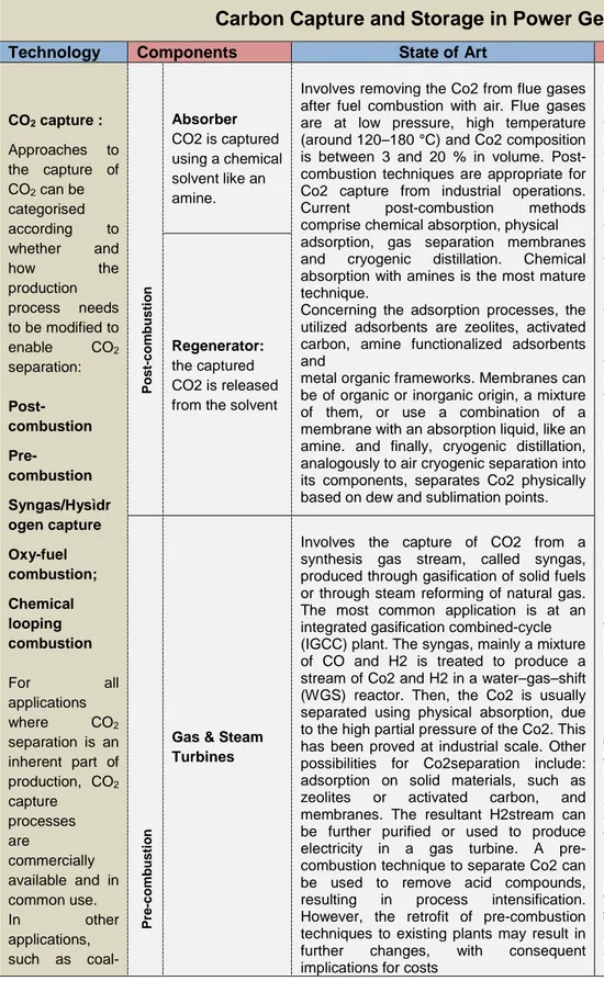
CO2 capture : Approaches to the capture of CO2 can be categorised according to whether and how the production process needs to be modified to enable CO2 separation: Post-combustion Pre-combustion Syngas/Hysìdr ogen capture Oxy-fuel combustion; Chemical looping combustion For all applications where CO2 separation is an inherent part of production, CO2 capture processes are commercially available and in common use. In other applications, such as coal-P o s t-c o m b u s ti o n Absorber CO2 is captured using a chemical solvent like an amine.
Involves removing the Co2 from flue gases after fuel combustion with air. Flue gases are at low pressure, high temperature (around 120–180 °C) and Co2 composition is between 3 and 20 % in volume. Post-combustion techniques are appropriate for Co2 capture from industrial operations. Current post-combustion methods comprise chemical absorption, physical adsorption, gas separation membranes and cryogenic distillation. Chemical absorption with amines is the most mature technique.
Concerning the adsorption processes, the utilized adsorbents are zeolites, activated carbon, amine functionalized adsorbents and
metal organic frameworks. Membranes can be of organic or inorganic origin, a mixture of them, or use a combination of a membrane with an absorption liquid, like an amine. and finally, cryogenic distillation, analogously to air cryogenic separation into its components, separates Co2 physically based on dew and sublimation points.
For the upcoming years, it will be important to:
• demonstrate integrated projects (regarding the complete value chain) to overcome unclear operational patterns;
• support the deployment of CO2 infrastructure;
• define a specific business case for CCS deployment;
• take advantage of knowledge sharing and of private–public partnerships;
• maximise the benefits (and the development) of local communities, going for a societal point of view; • perform a clear (stable) legal framework;
• gain public implication and acceptance .
Development of efficient solvent systems and processes for post- and pre-combustion capture. large-scale demonstration of oxy-fuel boilers for power plants and industry sectors and chemical looping are needed.
Example of large-scale CCUS projects in Europe
CCS Rotterdam Project
Implementation of a large-scale ‘CO2 Hub’ for capture, transport, utilisation and storage of CO2, with different point sources connected to multiple storage sites.
Zero emission Porto tolle Project (ZePt)
It exemplifies a retrofitting example of a power plant of
660 MW with postcombustion techniques in 40 % of the flue gas. The storage place is a deep saline aquifer.
Rotterdam opslag en Afvang demonstratieproject (Road)
The project includes capture of CO2 from a coal power plant, pipeline transportation and offshore storage in
Regenerator:
the captured CO2 is released from the solvent
P re -c o m b u s ti o n
Gas & Steam Turbines
Involves the capture of CO2 from a synthesis gas stream, called syngas, produced through gasification of solid fuels or through steam reforming of natural gas. The most common application is at an integrated gasification combined-cycle (IGCC) plant. The syngas, mainly a mixture of CO and H2 is treated to produce a stream of Co2 and H2 in a water–gas–shift (WGS) reactor. Then, the Co2 is usually separated using physical absorption, due to the high partial pressure of the Co2. This has been proved at industrial scale. Other possibilities for Co2separation include: adsorption on solid materials, such as zeolites or activated carbon, and membranes. The resultant H2stream can be further purified or used to produce electricity in a gas turbine. A pre-combustion technique to separate Co2 can be used to remove acid compounds, resulting in process intensification. However, the retrofit of pre-combustion techniques to existing plants may result in further changes, with consequent implications for costs
fired electricity generation, CO2 separation processes are less advanced or require considerable redesign of traditional processes. O x y -f u e l c o m b u s ti o n Air separation unit; Oxy-Boiler; gas Heater; Dust elimination unit; Desulphurizati on unit;
Is a newer approach: the technology aims to produce a purer CO2 stream after combustion using an O2 /CO2 stream instead of air. as a result, the flue gas contains CO2 at higher proportions (75–80 %), water vapour and only traces of impurities; therefore, relatively simple purification of CO2 is needed before storage. The process comprises air separation, combustion of the fuel and CO2 recycling to dilute the pure oxygen. This process suggests high efficiency lev-els and offers major business opportunities, including the possibility of retrofitting existing plants, even if the higher temperatures obtained with the oxygen combustion can be an issue. The main disadvantage is the large quantity of oxygen required, which is expensive both in terms of capital costs and energy consumption. There are three main oxy-fuel combustion pilot demonstration plants in the eU: Schwarze Pumpe in Germany, CiUdenin Spain and Lacq in France.
a depleted natural gas reservoir.
C h e m ic a l lo o p in g c o m b u s ti o n Air reactor; Fuel reactor.
In chemical looping combustionthe needed oxygen for the combustion is transferred by an oxygen carrier, generally an oxidised metal. as air is not used, the CO2 produced contains water vapour and the reduced met-al oxide. Therefore, purification only implies
condensation of water. Some common met-als used are iron, nickel, cobalt, copper, man-ganese and cadmium, driving to different working conditions of pressure and tempera-ture. This technology is still in the R&D phase
CO2
Transport Road tanker;
Ship; Pipeline.
The pipeline is the most important means of transport for development of an integrated infrastructur.
Even though hydrocarbons pipelines have been extensively used to transport CO2, for instance for enhanced oil recovery (EOR) in the US, in the north Sea or in the netherlands, it is necessary to requalify and inspect them for integrity assess-ment and materials evaluations. the CO2 stream has impurities that need to be limited regarding its final use/storage. In addition, existing CO2
pipelines work at 85–150 bar, while natural gas pipelines work at 85 bar or less.
CO2 Storage
Different types of geological
formations are
being used and
investigated: Oil/Gas reservoirs, Deep saline aquifer formations Unmineable coal beds
There is an estimated global storage potential of 10000 gigatonnes (Gt) CO2, with 117 Gt in Europe nearly all of which is in depleted oil and gas reservoirs and saline aquifers.
Current initiatives aim at creating a carbon atlas, to overlook sources, pipelines and storage sites’ locations.
For the 2030 horizon, CCS will have to be routinely implemented; the estimated emissions stored will be in the amount of 2000 Mt CO2/year. For the 2050 horizon, CCS will have to be further used, reaching 7 000 Mt CO2/year stored (iea, 2013c). Compressed CO2 is already injected into porous rock formations by the oil and gas industry, for eoR, and has been proven at commercial scale. typical storage costs per tonne of CO2 range from EUR 1.0–7.0 for onshore storage in depleted oil and gas reservoirs with legacy wells, rising up to EUR 6.0–20.0 for offshore storage in saline aquifers.
CO2 STORE Project
It aims at gaining knowledge on geochemistry and dissolution processes by monitoring CO2 migration onshore and offshore. The result is the development of methodologies for assessment, planning and monitoring.
Materials Road Map
Capture of CO2 requires functional materials that can separate efficiently CO2from a stream of flue and syn-gases. Increasing the efficiency of power plants, especially after the application of CCS, which is energy demanding, requires the increase of operating temperatures in boilers and burners, which in turn necessitates advanced materials that can operate in temperatures higher than those of today.In response to these needs, the materials proposes a research and development programme that focuses on the optimisation of functional materials for post combustion capture, such as solvents and advanced solvents, high temperature solid sorbents, other solid absorbers and membranes that could separate CO2with a low energy penalty.
Market
In the EU, 87.4 % of CO2-eq. emissions correspond to fossil fuel combustion. energy industries generate 34.5 %, followed by transport (22.7 %), and manufacturing and construction industries (22.7 %). the remaining 12.6 % mainly comes from other industrial processes and solvent use (5.3 %) and from international maritime transport (3.9 %).
According to the eU energy Roadmap 2050, CCS from the power sector will contribute with 19–32 % of the GHG emissions reduction by 2050. The installed capacity will have to grow from 3 GW in 2020 to 3–8 GW in 2030, 22–129 GW in 2040 and 50– 250 GW in 2050, depending on the energy system scenario. This would require about 20000 km of pipeline infrastructure. The IEA CCS technology Roadmap points out that the capture of CO2 has to be successfully demonstrated in at least 30 projects from power and industry sectors by 2020.