D.I.I.
–
D
EPARTMENT OF
I
NDUSTRIAL
E
NGINEERING
P
H.
D. D
ISSERTATION
D
OCTORAL
P
ROGRAM
IN
I
NDUSTRIAL
E
NGINEERING
XXXI
C
ycle
M
ULTI‐
P
HYSICAL
M
ODELLING AND
P
ROTOTYPING OF AN
E
NERGY
H
ARVESTING
S
YSTEM
I
NTEGRATED IN A
R
AILWAY
P
NEUMATIC
S
USPENSION
P
H
.D. C
ANDIDATE
I
NG.A
NDREAG
ENOVESES
UPERVISOR
P
ROF. I
NG. M
ICHELER
USSOC
O‐SUPERVISOR
P
ROF. I
NG. M
ARIOT
ERZOR
EVIEWER
P
ROF. I
NGS
TEFANOB
RUNI(P
OLITECNICODI
M
ILANO)
P
ROF. I
NGM
ASSIMOS
ORLI(P
OLITECNICODI
T
ORINO)
“Se sapessimo (esattamente) quel che stiamo facendo, non si chiamerebbe ricerca.” Albert Einstein
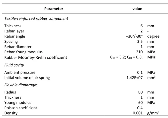
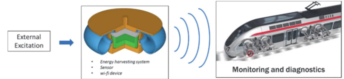
The aim of this PhD thesis is the investigation of an energy harvesting system to be integrated in a railway pneumatic spring to recovery otherwise wasted energy source from suspension vibration. Exploiting the piezoelectric effect to convert the mechanical energy into an electrical one, the final scope consists on the use of this system to power supply one or more sensors that can give useful information for the monitoring and the diagnostics of vehicle or its subsystems. Starting from the analysis of the energy sources, a multi‐physical approach to the study of an energy harvesting system is proposed to take into account all physics involved in the phenomenon, to make the most of the otherwise wasted energy and to develop a suitable and affordable tool for the design. The project of the energy harvesting device embedded in a railway pneumatic spring has been carried out by means of using a finite element technique and multi‐physics modelling activity. The possibility to combine two energy extraction processes was investigated with the purpose of making the most of the characteristics of the system and maximize the energy recovering. Exploiting commercial piezoelectric transducers, an experimental activity was conducted in two steps. A first mock‐up was built and tested on a shaker to develop the device and to tune the numerical model against experimental evidence. In the second step a full‐ scale prototype of an air spring for metro application with the EH system was realized. In order to test the full‐scale component, the design of a new test bench was carried out. Finally, the Air spring integrated with the EH device was tested and models validated.
Table of contents
List of figures ... 1 List of Tables ... 4 Notation ... 5 Introduction ... 7 Chapter 1 Energy harvesting: a multi‐physical approach ... 10 1.1 Energy harvesting: definition and motivation ... 10 1.2 Energy harvesting sources and techniques ... 13 1.2.1 Thermal energy harvesting ... 15 1.2.2 Photonic energy harvesting ... 17 1.2.3 Electromagnetic energy harvesting ... 18 1.2.4 Kinetic energy harvesting ... 19 1.3 Multi‐physical approach ... 25 Chapter 2 Application Field: Railway industry ... 27 2.1 Railway system overview ... 27 2.1.1 Railway system description ... 27 2.1.2 Railway systems condition monitoring ... 29 2.2 Energy harvesting in Railway: literature review ... 31 2.3 Excitation source analysis ... 35 2.3.1 Generalities ... 35 2.3.2 Vibrations induced by track unevenness ... 37 2.4 Railway vehicle modelling ... 41 2.4.1 Two‐degree‐of‐freedom model, a quarter of vehicle ... 42 2.4.2 Nine‐degree‐of‐freedom model ... 45 Chapter 3 Energy harvesting device integrated in the pneumatic spring ... 50 3.1 Railway pneumatic suspension ... 503.2 Air spring modelling ... 53 3.3 Proposed device: energy harvester integrated in the air spring ... 58 3.3.1 System description ... 58 3.3.2 Operation principle... 61 3.3.3 Remark ... 63 3.4 Reference air spring ... 63 Chapter 4 Finite element study of the harvester integrated in the air spring ... 65 4.1 Finite Element model description ... 65 4.2 Static analysis ... 68 4.2.1 Air spring model static verification ... 68 4.2.2 Flexible diaphragm model static validation ... 70 4.3 Dynamic analysis ... 74 4.3.1 Linear modal analysis ... 74 4.3.2 Nonlinear analysis ... 76 Chapter 5 Energy harvesting device integrated in the air spring multi‐physical modelling ... 81 5.1 Mechanical part ... 82 5.1.1 Lumped parameter model of the kinetic harvester ... 82 5.1.2 Air spring with a volume‐variable auxiliary chamber model ... 85 5.1.3 Mechanical part (air spring – harvester) modelling summary ... 90 5.1.4 Power extraction consideration ... 91 5.2 Piezoelectric transduction mechanism ... 98 5.2.1 Generalities ... 98 5.2.2 Piezoelectric effect modelling ... 99 5.3 Electrical part ... 102 5.4 Multi‐physical model of energy harvester ... 103 5.4.1 Power conversion considerations ... 109 5.5 Conclusion ... 110
Chapter 6 Energy harvesting device prototyping and testing ... 112 6.1 Experimental activity on the shaker ... 112 6.1.1 EH device prototyping ... 112 6.1.2 Experimental setup and preliminary tests ... 115 6.1.3 EH device testing and results ... 119 6.2 Full‐scale testing activity ... 125 6.2.1 EH system integrated in a pneumatic spring prototyping ... 125 6.2.2 Test rig design ... 127 6.2.3 Experimental setup and testing procedure ... 133 6.2.4 Results and discussion ... 134 Conclusions and future developments ... 138 References ... 140 Appendix A ... 147
List of figures
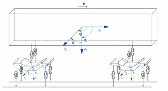
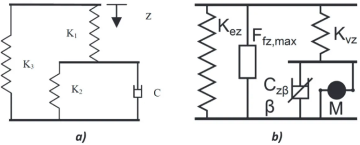
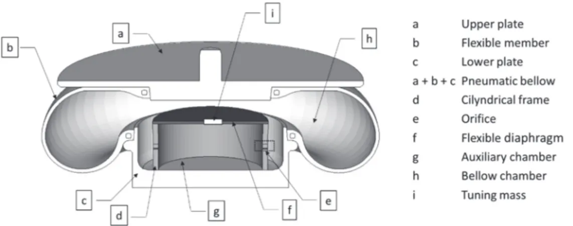
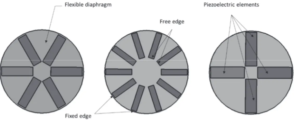
Figure 0.1 Illustration of vision of the research activity ... 8 Figure 1.1 Mems and sensor market and forecast [9]. ... 11 Figure 1.2 Motivations that push the interest to the energy harvesting ... 12 Figure 1.3 Documents whit Energy harvesting keywords in Scopus database over the years ... 13 Figure 1.4 Seedbeck based thermal energy harvesting scheme. ... 16 Figure 1.5 A typical solar cell scheme [36]. ... 17 Figure 1.6 Kinetic EH system: Scheme and main energy flows. ... 19 Figure 1.7 Kinetic energy harvesting transduction mechanism ... 24 Figure 1.8 EH functional energy flow. ... 25 Figure 2.1 Train configuration ... 29 Figure 2.2 Illustration of typical sensor placement on vehicle a) and track b) [63]. ... 30 Figure 2.3 Track vibration energy harvesting by Tianchen et al. [66]. ... 32 Figure 2.4 Smart system for monitoring rail breaking system [70]: Sensor mounted on break beam a) and prototype of energy harvester b). ... 33 Figure 2.5 Cantilever beam harvester prototype by De Pasquale et al. [71]. ... 33 Figure 2.6 Freight train energy electromagnetic harvester [72]: schematic layout (a) and prototype (b). ... 34 Figure 2.7 Rail vehicle dynamics coordinate system and nomenclature of motions. ... 36 Figure 2.8 Schematic excitation flow induced by track irregularities. ... 37 Figure 2.9 Symmetrical (a) and antisymmetrical (b) bounce of the axles planes. ... 38 Figure 2.10 Symmetrical (a) and antisymmetrical (b) pitch of the axles planes. ... 39 Figure 2.11 Example of the vertical acceleration measured on the car body floor of a high‐speed train at about 210 km/h: time history (a) and corresponding Fourier transform (b) [79]. ... 40 Figure 2.12 Two‐degree‐of‐freedom rail vehicle model. ... 42 Figure 2.13 Time‐domain response of the two‐DOF model for 1.2 Hz sinusoidal excitation. ... 44 Figure 2.14 Time‐domain response of the two‐DOF model for 7.9 Hz sinusoidal excitation. ... 44 Figure 2.15 Rail vehicle model for vertical dynamics. ... 46 Figure 3.1 Schematic illustration of air spring main components. ... 51 Figure 3.2 illustration of the various component of a pneumatic secondary suspension as represented by Nakajima et al. [87]. ... 52 Figure 3.3 Bellows‐tank equivalent vertical mechanical models: a) Oda‐Nishimura and b) Berg. ... 54Figure 3.4 Thermodynamic scheme for air spring model. ... 55 Figure 3.5 Location of the proposed EH system in the vehicle excitation flow. ... 58 Figure 3.6 Illustration of resonant system integration in the air spring. ... 59 Figure 3.7 Layout of the energy harvester included in the air spring ‐ sectioned view. .. 60 Figure 3.8 Possible layouts of commercial piezoelectric transducer on the flexible diaphragm. ... 61 Figure 3.9 Operation principle of diaphragm deformation caused by pressure gradient between bellow chamber (BC) and auxiliary chamber (AC). ... 62 Figure 3.10 reference air spring (a) and its 3D CAD reconstruction (b). ... 64 Figure 4.1 Air spring‐harvester finite element model. ... 67 Figure 4.2 Bellow volumetric change in finite element simulation. ... 69 Figure 4.3 Force –displacement curve for different inflation pressure. ... 70 Figure 4.4 Amplified deformed shape of flexible diaphragm for a 10 mm static load at its centre. ... 71 Figure 4.5 Flexible diaphragm stiffness as a function of its centre vertical displacement. ... 71 Figure 4.6 Experimental layout for the determination of FD static stiffness. ... 73 Figure 4.7 Measured data and fitting curve for static loads at flexible diaphragm centre ... 73 Figure 4.8 Flexible diaphragm stiffness‐displacement curve: Simulation vs. experimental ... 74 Figure 4.9 Mode shapes of the flexible diaphragm: a) 8 Hz; b) 39 Hz; c) 46 Hz. ... 75 Figure 4.10 Dynamic nonlinear response of diaphragm centre for a smooth step external excitation ... 77 Figure 4.11 Air pressure variation inside the air spring under an 8 Hz sinusoidal load. .. 77 Figure 4.12 Dynamic response of FD centre compared to 8 Hz sinusoidal excitation. .... 78 Figure 4.13 Flexible diaphragm nonlinear deformed shape. ... 79 Figure 4.14 Reference system of FD elements in finite element simulations. ... 79 Figure 4.15 Stress evolution in an element of FD for an 8 Hz sinusoidal excitation. ... 80 Figure 5.1 Equivalent mechanical model of proposed energy harvester integrated in the air spring. ... 83 Figure 5.2 Thermodynamic scheme for air spring with a volume‐variable auxiliary chamber model. ... 86 Figure 5.3 Deflection in one diametrical section of flexible diaphragm. ... 88 Figure 5.4 Comparison between results obtained exploiting only base motion source and the combined sources in terms of FD centre displacements. ... 95 Figure 5.5 Comparison between results obtained exploiting only base motion source and the combined sources in terms of extractable power. ... 96 Figure 5.6 Pressure difference between BC and AC for different orifices dimension. .... 97 Figure 5.7 Flexible diaphragm centre deflection in function of orifices dimension... 97
Figure 5.8 Piezoelectric material in 33 and 31 operating mode ... 100 Figure 5.9 Piezoelectric material patch used as energy harvester in the 31 mode ... 100 Figure 5.10 Piezoelectric EH in radial pattern based on FD: a) top view and b) enlarge schematic section view... 103 Figure 5.11 Simplified scheme for the calculation of piezoelectric element elongation due to bending. ... 105 Figure 5.12 Simplified scheme for the calculation of piezoelectric element elongation due to traction. ... 107 Figure 6.1 Flexible diaphragm and cylindrical frame. ... 113 Figure 6.2 Possible arrangements of the piezoelectric rectangular patches on the FD. 114 Figure 6.3 Energy harvesting device prototype. ... 115 Figure 6.4 Experimental setup... 116 Figure 6.5 Preliminary test, sweep response for FD. ... 117 Figure 6.6 Preliminary test, frequency response. ... 117 Figure 6.7 Input velocity signal for a 10 Hz base excitation. ... 119 Figure 6.8 FD centre velocity for a 10 Hz sinusoidal base excitation. ... 120 Figure 6.9 Comparison between input velocity and FD centre velocity for a 10 Hz base excitation. ... 120 Figure 6.10 Prototype testing: frequency response in terms of velocity ratio. ... 121 Figure 6.11 Voltage generated by one piezoelectric element for a 10 Hz sinusoidal base excitation. ... 121 Figure 6.12 Prototype testing: frequency response in terms of power generation. ... 122 Figure 6.13 piezoelectric elements location during the shaker tests. ... 123 Figure 6.14 Generated voltage: experimental vs. simulation results. ... 125 Figure 6.15 Project of full‐scale prototype. ... 126 Figure 6.16 Cylindrical steel frame dimension. ... 126 Figure 6.17 EH integrated in the air spring prototype. ... 127 Figure 6.18 Existing seismic test rig [113]. ... 128 Figure 6.19 Seismic test rig removed parts. ... 129 Figure 6.20 Test rig designed component: a) sliding table, b) moving support, c) reaction structure, d) interface. ... 130 Figure 6.21 Re‐designed test rig assembly. ... 130 Figure 6.22 Moving support finite element analysis. ... 131 Figure 6.23 Reaction fixed structure finite element analysis. ... 131 Figure 6.24 Air spring test rig: design and construction... 132 Figure 6.25 Testing procedure for the full‐scale tests. ... 134 Figure 6.26 Measured reaction force for a 9 Hz sinusoidal excitation. ... 135 Figure 6.27 Measured reaction force for a 9 Hz sinusoidal excitation. ... 136 Figure 6.28 Generated voltage for a 9 Hz sinusoidal excitation. ... 136 Figure 6.29 Full‐scale testing frequency response in terms of power generation. ... 137
Figure 6.30 Generated voltage for a 12 Hz sinusoidal excitation. ... 137 Figure A.0.1 V‐ELA instrument ... 148
List of Tables
Table 1.1 Typical data for various energy harvesting techniques [24]... 15 Table 1.2 Acceleration magnitude and frequency of some vibration sources [45]. ... 21 Table 1.3 Vibration sources exploitable for energy harvesting in the surrounding [46]. 22 Table 2.1 Vehicle parameters for two‐degree‐of‐freedom dynamic analysis ... 43 Table 2.2 Parameters of rail vehicle model for vertical dynamics. ... 46 Table 3.1 Reference air spring main parameters ... 64 Table 4.1 Finite Element model parameter. ... 68 Table 4.2 Main technical specification of the natural rubber used as flexible diaphragm. ... 72 Table 4.3 Dynamic linear response of flexible diaphragm centre. ... 75 Table 5.1 Main parameters for mechanical part simulation ... 95 Table 6.1 Main parameters of piezoelectric patch... 114 Table 6.2 Model parameters. ... 124 Table 6.3 Model identification parameter results. ... 124 Table 6.4 Finite element main results for the reaction structures. ... 132Notation
Symbol Description Unit
a plate radius [m] AC Auxiliary chamber Ae Effective area [m2] b critical pressure ratio [‐] BC Bellow chamber C Viscous damping coefficient [Ns/m] Cp piezoelectric output capacitance D sonic conductance DOF Degree of freedom e Orifice effective area [m2] EH Energy harvesitng F force [N] f frequency [Hz] FD Flexible diaphragm G Mass flow rate [Kg/s]
i current [A]
IoT Internet of Things K stiffness [N/m] k polytropic exponent M mass [Kg] m Air mass [Kg] MEMS Micro Electro‐Mechanical Systems NDE Non‐Destructive Evaluation P Pressure [Pa] R universal gas constant [J/kgK] RL Resistive load S mechanical strain [‐] SHM Structural Health Monitoring T temperature [K] t time [s] V volume [m3] Vp Piezoelectric voltage [V] VT Voltage generate by the transducer [V] W power [W] WSNs wireless sensor networks z1 Absolute displacement of air spring lower plate [m] z2 Absolute displacement of air spring upper plate [m] z3 Absolute displacement of flexible diaphragm centre [m] zr Relative displacement of FD centre respect to air spring lower plate [m]
α, β and γ electromechanical coupling coefficients of the transducer Γ generalized electromechanical coupling factor ε Mechanical elongation [m] εb Elongation due to the bending [m] εt Elongation due to the traction [m] ρ density [kg/m3] σ mechanical stress [Pa] ω radian frequency [rad/s] ξ Damping ratio Subscripts Description 0 Initial condition ac Auxiliary chamber air Air spring atm atmospheric av average bc Bellow chamber bm Base motion el electric extr extractable FD Flexible diaphragm H harvester pl Pressure load
Introduction
The activities described in this PhD thesis derive from the interest of Applied Mechanics Research Group of the Department of Industrial Engineering of University of Naples Federico II in starting a new research line in energy harvesting and its possible applications.
In the past decades, the research effort in energy harvesting from both academics and private sector has increased exponentially due to the plethora of possible applications. This increased interest is due to the convergence of different factors, with the most prominent being the enormous progress made in the field of semiconductors. It substantially reduced energy consumption and size of electronic devices leading to the invasion of Micro Electro‐Mechanical Systems (MEMS). In turn, the development and widespread adoption of these low‐powered systems led to the birth of the age of portable electronics, miniature sensors and actuators that have a wide range of applications. Portable devices, GPS system and biomedical devices are some of most known applications. In the industrial field, more specific use of these technologies regards Wireless Sensor Nodes (WSNs), Structural Health Monitoring (SHM), Non‐ Destructive Evaluation (NDE) and more recently the Internet of Things (IoT). These applications are based on the use of wireless self‐powered sensors with the aim of measuring and transmitting extensive data for monitoring of objects or activities like industrial processes, structures, machines, vehicles, environment, healthcare and traffic. In this context, the work presented here concerns a multi‐physical approach to the study of an energy harvesting system. The focus is on exploiting otherwise wasted energy source of a specific environment to power supply a sensor. In particular, following the personal research background in railway [1]–[7], we propose an energy harvesting system to be integrated in a railway pneumatic spring that exploits the piezoelectric effect to convert the mechanical energy into an electrical one. The final vision is to create an autonomous and smart air spring capable of collecting information for the monitoring and diagnostics of the vehicle or its subsystems: to achieve this goal we designed this system, coupled with sensors, to be self‐powered. The study presented in this thesis is based on the idea of harvesting energy by exploitation of existing components. The innovative vision is the integration of a generator, electronic and sensing system in the existing space available in the components, avoiding wire cablings.
Nowadays, the railway industry is moving forward at a fast pace and railway vehicles have changed from being an essentially mechanical system to one that increasingly
includes electronics, computer processing and sensors. These technologies play a fundamental role in train management, communication, monitoring and control for vehicle dynamics, leading to improvement in terms of safety, performance, comfort and reducing life‐cycle cost.
Figure 0.1 Illustration of vision of the research activity
The first step was to study the extended scenario related to the energy harvesting, analysing the different strategies and focusing to the kinetic energy harvesting techniques. This phase of study, descripted in the Chapter 1, motived the choice of a multi‐physical approach. In the Chapter 2 the railway system is analysed in the prospective of energy harvesting. After a brief a description of the railway system, the requirement of these system, which make this field of application particularly suitable for the energy harvesting, are pointed out. Then a literature review of the energy harvesting technologies targeted for railway systems is presented. The analysis of the source and mechanism of excitations, necessary for the device design, is then presented also by resorting to parametric mathematical models of vehicle dynamics.
The device layout integrated in the pneumatic spring is presented in Chapter 3 alongside a detailing of the system hardware and an explanation of the operation principle. To better understand the idea, first a pneumatic suspension system is analysed in details and an overview on the air spring modelling approach is presented, focussing on the multi‐physics techniques.
Chapter 4 and 5 are dedicated to the modelling of energy harvesting devices integrated in the railway pneumatic spring. We propose an integrated modelling approach to accurately describe the phenomena building on the concept that the dynamic of the harvester is strictly influenced by the air spring type and working condition and, vice versa, the presence of the harvesting system modifies the geometry of the bellow. In particular, we first present in the 4th chapter a finite element model that was developed
to preliminary study the dynamic behaviour of the assembly. Then in the 5th chapter we
the assembly of different domains contributions into one set of coupled equations to be solved in the same environment by the same integrator.
In Chapter 6 the experimental activities are described. The piezoelectric energy harvesting system integrated in an air spring was designed, prototyped and experimentally tested. These activities were conducted in two steps. In the first one a mock‐up was prototyped and tested on a shaker, considering just the base motion excitation mechanism. In the second step a full‐scale prototype of an air spring with the EH system was built, a new test designed and several tests were carried out.
Chapter 1
Energy harvesting: a multi‐physical
approach
This chapter is intended to give the reader a brief and general view of the energy harvesting scenario, with a focus on the kinetic energy harvesting brand. It gives a comparison between the main energy sources and techniques for harvesting and a general review of the possible power conversion mechanisms. We then focus on motion‐ based energy harvesting, where the energy flow, the possible sources and comparison of the main transduction mechanism are analysed. Finally, the used approach to the topic is motivated.
1.1 Energy harvesting: definition and motivation
Many definitions can be found in literature under the header ‘energy harvesting’, one of the most common defines energy harvesting, or energy scavenging, as the recovery of energy from freely available environmental resources. Building on this definition, some consideration can be made. Referring to the amount of obtainable energy we speak about different EH scales. Strictly speaking, macro‐scale EH technologies in the form of windmills, watermills and passive solar power systems have been around for centuries. Nowadays, with the global energy crisis and environmental concerns, many technologies have advanced considerably to include devices in large EH scale. The solar, wind, geothermal and hydraulic power plants or farms are such examples [8]. These are usually referred to as renewable energy devices and are fundamental in the effort to face the environmental and pollution issues. Vibration, given its ubiquitousness, has also became a good alternative energy source, it can be found almost everywhere: floors and walls, vehicles, jet engine housings, human motion, etc. It has received increasing attention in recent years for macro scale. These macro‐scale harvesting technologies might differfrom each other in many ways but they all share the same task of feeding the power grid distribution system, alternatively or complementary to traditional sources.
Nevertheless, most of the current research activities on EH are focused on the small‐ scale, from the µW to the W, so much that in the literature, where not differently specified, the terms EH refers to the energy recovery from freely available environmental resources at that scale. This is due to different factors, with the most prominent one being the enormous progress made in the field of semiconductor in the past decades. It substantially reduced energy consumption and size of electronic devices leading to the invasion of Micro Electro‐Mechanical Systems (MEMS).
The development of these low‐power systems has revolutionized the market (figure 1.1) giving birth to the age of portable electronics, miniature sensors and actuators that have a wide range of applications ranging from portable mobiles and GPS system to more specific ones such as Wireless Sensor Nodes (WSNs), Structural Health Monitoring (SHM), Non‐Destructive Evaluation (NDE) and Internet of Things (IoT). Figure 1.1 Mems and sensor market and forecast [9]. In many of these applications the microsystem is completely embedded in the structure, it has the need to be wireless with no physical connection to the outside world. The main issue with this is that a wireless device requires its own power supply. The traditional solution for power supply is the use batteries that have be included in the design of such devices. However, batteries present some undesirable aspects: they have a limited
lifespan, a limited amount of energy, tend to be quite bulky, present maintenance costs and contain chemicals whose disposal is problematics.
For example, consider a battery powered wireless sensor deployed in a remote and hostile environment: once the stored energy in the battery has been exhausted, to replace the power supply the device must be physically recovered, implying often a great inconvenience and significant costs [10]–[12].
The introduction of Low and Ultra‐Low‐Power electronics has led to a large reduction in consumption of wireless sensors [13]: the typical power need of mobile devices ranges between hundreds of milliwatts for MP3s, mobile phones and GPS applications to few micro‐watts for wristwatches, RFID, MEMS sensors and actuators. Considering that usually these devices are in a sleep state up to 99.9% of their operation time, waking up only to transmit data for few milliseconds, their average power consumption is below 10μW. In order to compare energy demand and supply, a lithium battery can provide 30μW/cc for 1 year or 30mW/cc for just 10 hours, while a vibration‐driven generator could last for at least 50 years with the same power level [14]. On this way the EH is a complementary or alternative solution to batteries, it offers a method for their autonomous recharging and in some situations even their elimination. Thus, these small‐ scale generators have turned harvesting into a small but growing contributor to the world’s energy needs. This technology offers two main advantages over battery‐powered solutions: virtually inexhaustible sources and little or no adverse environmental effects. Furthermore, the energy is recovered form otherwise waste sources or from sources that are not significantly influenced by this process. Figure 1.2 Motivations that push the interest to the energy harvesting
These motivations have led to an increasing research effort in energy harvesting (EH) from both academics and industrialist over the years as evident from the rising number of publications and product prototype, since the end of 90s to date (figure 1.2). In the figure 1.3 are reported the documents by year that use the term “energy harvesting” in the keywords or in the title, collected in the databases Scopus and Web of Science. Figure 1.3 Documents whit Energy harvesting keywords in Scopus database over the years
1.2 Energy harvesting sources and techniques
The term EH, according to the definition given above, is ordinarily used to indicate the process of the extraction and conversion of otherwise wasted energy, available in the ambient, into electrical energy. The application scale is typically small and is linked to the supply of low‐power electronic devices.An EH system is composed by a transducer, that converts energy from one type to another, usually electricity, and by a target electronics that consumes or stores this energy. The target device can be driven synchronously, using the recovered energy directly, or asynchronously, recharging temporary storage systems such as capacitors or batteries. In any case the device that uses the energy needs to be designed to work with energy harvesting as the power source.
Starting with the concept of ubiquitous energy: the energy is everywhere in the environment that surrounds us and is present in different forms. These kinds of energies
are potential sources for the EH process by exploiting appropriate phenomena and materials. These sources have the great advantage of being essentially free and of not having pollution attributable to the conversion mechanisms.
EH systems classification can be made either by conversion methods or by sources. There are five main methods for energy harvesting: piezoelectric, thermoelectric, photovoltaic, electromagnetic and electrostatic.
It is possible to classify EH sources in different ways. A first classification considers who or what provides the energy for conversion. In this classification scheme Mateu and Moll [15] distinguish two kinds of devices: devices that use part of the energy of the user of the electronic appliance and devices that get their energy from the environment. The user of first kind of devices is usually a human, but it could also be an animal: thus these devices are called Human Energy devices. The second kind of EH devices get their energy from the environment, and thus they are called Environment Energy devices. Another possible classification is based on the type of EH sources. According to Harb [16] and Thomas et al. [17] we can identify the following categories for small‐scale EH: ‐ Thermal: Thermal gradient and temperature fluctuation over the time. ‐ Photonic: solar and light for indoor and outdoor. ‐ Pressure gradient. ‐ Micro water flow. ‐ Electromagnetic waves or radio frequency (RF). ‐ Biological. ‐ Kinetic: motion, vibration or mechanical energy.
Furthermore, in recent works chemical sources are also considered [18], [19]. In literature many classifications consider only mechanical, thermal, and solar energy as main sources, while pressure gradient and water flow are included in the kinetic/mechanical sources and biological and electromagnetic are not yet widely used. Here, the focus is on the kinetic EH thus the state‐of‐the‐art of the other principal EH techniques is only briefly outlined in order to better understand the research field and compare the main results. For an exhaustive and comprehensive framework on EH techniques, in addition to the review of Harb [16] and Thomas et al. [17], you may refer to the documents of Fan et al. [20], Tang et al. [21], Ahmed et al. [22], Mathúna et al.[23], Chalasani et al.[24] , Paradiso and Starner [25], [26], Gilbert and Balouchi [27], Wei and Jing [28].
Several properties can be considered to characterize energy suppliers and compare different possible solutions. Fry et al in [29] provide a comprehensive list of these properties that includes: physical properties such as the size, shape and weight; electrical
properties like power density, maximum voltage and current; environmental properties as water resistance and operating temperature range; and operational and maintenance properties. For most EH applications, like that of portable devices, required properties are small dimensions, limited weights and, consequently, adequate power density. The power density is defined as the amount of power that can be produced per volume or sectional area of the device and is generally expressed in µW/cm3 or µW/cm2. This
parameter is very important for portable devices as it states the minimum device volume that is required to harvest the amount of power needed, indeed results less fundamental in integrated systems that exploit dimensions already available in the existing components as well as the one conceived in this work. In any case, the impact that the harvesting produces on the subject environment must be evaluated and if necessary taken into account. In table 1.1 are reported the typical values of power generation capability for some EH techniques.
Table 1.1 Typical data for various energy harvesting techniques [24].
Energy harvesting method Conditions Power density
Vibration 1 m/s2 100 µW/cm3 Solar Outdoors 7500 µW/cm2 Solar Indoors 100 µW/cm2 Thermal 5°C temperature gradient 60 µW/cm2
1.2.1 Thermal energy harvesting
The main way in which thermal energy is harvested is exploiting temperature gradients. The phenomenon of creating electric potential with a temperature difference and vice‐ versa in known as thermoelectricity. The thermoelectric EH is based on the Seedbeck effect, which is the conversion of heat directly into electric energy by means of thermocouples. A simple construct of a thermocouple is shown in figure 1.4, consisting of two pillars made of a thermoelement (generally alternating n‐type and p‐type semiconductors) connected in series by a metallic conducting strip.In situations where thermoelectric generators are used for energy harvesting, many thermocouples will be connected electrically in series and thermally in parallel. The effectiveness of these conversions is limited by the Carnot efficiency.
(1.1)
Where and are respectively the absolute temperature of the hot and cold side of the device. From this equation is clear that the greater the temperature gradient, the larger the conversion efficiency. In [17] is pointed out that the small conversion efficiency for modest temperature gradient is 3% at ∆T=10°C; 14% at ∆T =50°C; only 40% at ∆T = 200°C. Many of these largescale devices exist, for example, for the generation of electricity from hot exhausts on vehicles. At a smaller scale, the main interest has been in the generation of power from body heat, to power wearable devices. Considering the thermal gradient between the human body, 37 °C, and a typical environment temperature, 20 °C, Paradiso et al. evaluate a conversion efficiency of 5.5% [26]. Another wearable thermoelectric device that exploit a temperature difference of 15 °C between human skin and the surrounding environment, was proposed by Kim et al. [30]. It can generate a voltage output of 3mV. Figure 1.4 Seedbeck based thermal energy harvesting scheme. Despite thermoelectric generators are considered to have long life, low maintenance and high reliability, their diffusion is limited because of their low energy conversion efficiency for small temperature gradients and high costs [31]. Higher temperature differences may be achievable in other environments, e.g. heaters in a building, geothermal steam (80–180°C), solar ponds (∼75°C), waste heat generated by power plants (15°C) and industrial waste heat sources (75°C).
Besides the thermoelectric process there are several ways to exploit the thermal gradient: thermionic, thermomagnetism, ferroelectricity and the Nernst effect [32]. At present, the thermoelectric conversion results the most effective of these processes. A different concept for thermal EH is based on the temperature fluctuation over time. In this case is exploited the pyroelectric materials property of showing spontaneous electrical polarization as function of temperature. It follows that temperature time fluctuation causes induced charge variations and consequently current [33]. Materials used in pyroelectric devices include piezoelectric materials such as PZT (lead zirconate
titanate) and PVDF (polyvinylidene fluoride). Nowadays, the main commercial application for pyroelectricity is for sensors in thermal imaging cameras, but many other studies for energy harvesting based on this phenomenon can be found in literature.
1.2.2 Photonic energy harvesting
Photonic EH, also known as solar and light EH, exploits the photovoltaic phenomenon that consists in the conversion of light energy into electrical energy by means of appropriate materials. The form of energy exploited is typically light energy obtained from solar radiation that delivers approximately 124PW (PW= 1015 Watts) globally to the surface of the Earth [33]. However, the power available from the energy conversion in the solar cells, varies widely depending on several factors. Indoors or outdoors location, sunny or cloudy day, geographical location, distance between the sun and the Earth are some of the variables which can influence the radiation/illumination level (e.g. indoors or outdoors, sunny or cloudy day) [34], [35]. Approximately 1000 W/m2 of solar power isincident on surfaces directly facing the sun on a bright sunny day. A solar cell can be depicted as reported in figure 1.5. It is composed by a semiconductor diode with a large p–n junction in the plane of the cell that is positioned close to the top surface. When the cell is exposed to photonic radiation, an electric potential develops between the p‐ and n‐type materials. Figure 1.5 A typical solar cell scheme [36]. The most common photovoltaic cells are the silicon‐based cells: single crystal, polycrystal, ribbon and sheet, and thin‐layer forms. These present an efficiency range from 10% to 23 % in a state‐of‐art cell and a good price to performance ratio. Commercial solar conversion efficiencies of 30% or more exploit other solar technologies that include the high efficiency multi‐junction devices, which stack different photovoltaic cells on top of each other to maximize the capture of incident radiation, and thin film solar cells. Experimental devices can reach about 35%.
For wireless sensor nodes application Thomas et al. [17] assume the power density of 75 µW/mm2 for outdoor solar cell operation and a power density of 1 µW/mm2 for indoor operation.
1.2.3 Electromagnetic energy harvesting
Base stations, wireless internet, mobile phones, satellite communication, radio, TV’s, digital multimedia broadcasting and X‐rays are some of the electromagnetic radiation source, also known as radio frequency, RF, radiation. One must not confuse between electromagnetic energy source and electromagnetic transducer. In some articles, electromagnetic generator is used for electromagnetic transducer [16]. The energy associated with electromagnetic radiation can be collected for use by an appropriately designed antenna that converts it into an alternating electric current [37]. The key units of an RF power harvesting system are the antenna and the rectifier circuit that allows the RF power or alternating current to be converted into direct current energy [38]. As described in [39], the amount of received power is a function of the following: the wavelength, the transmitted power, the gain of both the transmitting and the receiving antenna and the distance between source and harvester. This last parameter is a key factor that mainly influence the power losses and so the harvestable energy as the transmitted power quadratic decrease with it. Other losses occur in the internal circuitry of the harvester. Considering the normal sources of radiation like standard transmitter or alternate current cables, the harvested power is usually quantifiable in less than 1μW [26].
Nishimoto et al. [39] propose a low‐cost approach using RF energy harvesting from ambient RF fields; this approach relies mainly on TV broadcast signals. TV broadcast signals that are not received by TV viewers are generally dissipated as heat resulting in a waste of energy. This wasted energy can be utilized to power a low‐power sensor node. Other applications of wireless charging with regard to near‐field and far‐field practices to better illustrate the diverse and promising use of this techniques are reported in [40]. This article provides a comprehensive survey of the emerging wireless charging systems and their fundamental technologies, international standards as well as applications in wireless communication networks.
1.2.4 Kinetic energy harvesting
The kinetic energy harvesting can be defined as the recovery and conversion of mechanical energy into electrical one. The general opinion from the literature is that while each application should be evaluated individually with regards to finding the best energy‐harvesting method, kinetic energy in the form of motion or vibration is generally the most versatile and ubiquitous ambient energy source available [41].
Kinetic EH schematization and energy flow.
The recovery and conversion process of mechanical sources and consequent electrical energy consumption or storage occurs through a complex system called energy harvesting. According to Manca, in his PhD thesis [42], this system performs three main functions: energy extraction, energy conversion and energy transfer/management. Following this energy flow, the kinetic EH system can be schematically considered composed of three main parts/domains in which the functions are carried out. Firstly, there is the mechanical part, often‐named energy harvester, designated to extract the energy from the environment to make it usable for the conversion. The second part consists in the transduction mechanism, or the transducer, that converts the extracted mechanical energy into electrical one by exploiting a physical phenomenon of electromechanical coupling. Finally, the electrical part is tasked with managing and transferring energy to the electric load. Figure 1.6 shows the kinetic EH system general schematization and the main energy flows that cross it. Figure 1.6 Kinetic EH system: Scheme and main energy flows. Here it should be emphasized that even if the overall energy flow through the system is from the mechanical domain, which represent the EH system input, to the electrical one, which is the output, a backward energy flow is present and must be considered. Indeed, by means of the transducer, the two domains are coupled and while the mechanical energy is transferred toward the electrical domain, the electrical energy is transferred
backward to the mechanical domain. Generally, this backward flow does not have any effect on the source since the harvestable energy is negligible with respect to the source itself. Nevertheless, this domains coupling influences the dynamics of the harvester and thus the amount of energy that can be extracted from the environment. This is the reason why for the analysis of the EH system and for its design related to a specific application, both domains must be considered together. Kinetic EH sources
The mechanical energy source that has to be extracted by the system may assume different forms. A useful classification has been provided by Gilbert and Balouch [27]. They divided sources of mechanical energy in three main groups depending on the type of motion: sources in which the motion is essentially constant over extended periods of time; intermittent motion; and cyclic motion as in vibration sources ‐ The Steady state mechanical sources are the ones in which the motion is quasi‐ constant over time. This kind of source is typical of fluid flow as well as in wind, air current and water flow either in natural channels or through pipes. Fluid flow based EH is widespread on the macro scale for electrical power generation as in wind turbines and hydroelectric plants. Recently this source has also been investigated for smaller scale applications [43], [44]. Another form of continuous motion regards objects such as a rotating shaft.
‐ For intermittent mechanical sources is intended the energy available from motion which may be cyclic in nature but in which the energy is only available for a short part of the cycle. Energy sources like these are available during vehicles passage over opportune EH device or in human normal walking or running.
‐ The principal type of cyclic sources are mechanical vibrations. Among other harvestable energy sources such as solar, radio frequency RF, thermal and biochemical, kinetic energy in the form of mechanical vibrations is deemed to be the most attractive in the low‐power electronic domain, this is because of its power density, versatility and abundance. The amount of extractable energy mainly depends on the amplitude of the vibration and its frequency. Furthermore, it can vary dependently on the impact the presence of EH device causes on the source.
Low‐level vibrations occur in many environments such as buildings, automobiles, aircraft, ships, trains, industrial environments, vibrating machineries and human beings. Being the nature of vibration very variable with the phenomenon that
generates them, the amplitude and dominant frequency can range in a wide spectrum. In table 1.2 are reported the measurements performed by Roundy et al. [45] for a number of vibration sources in terms of frequency and acceleration magnitude of the fundamental vibration mode. Table 1.2 Acceleration magnitude and frequency of some vibration sources [45]. Vibration source A (m/s2) f peak(Hz) Car engine compartment 12 200 Base of 3‐axis machine tool 10 70 Blender casing 6.4 121 Clothes dryer 3.5 121 Person nervously tapping their heel 3 1 Car instrument panel 3 13 Door frame just after door closes 3 125 Small microwave oven 2.5 121 Windows next to a busy road 0.7 100 CD on notebook computer 0.6 75 Second story floor of busy office 0.2 100 Car engine compartment 12 200
A committee formed during the Second Annual Energy Harvesting Workshop held on January 30–31, 2007 in Fort Worth, TX, drew up a comprehensive list of potential vibration sources for energy harvesting. This committee, formed by members from academia, industry, and federal labs, had the purpose to create a first draft of Standard in vibration EH [46]. The vibration sources were classified both according to their elastic stiffness and according to the surrounding. In table 1.3, the vibration sources grouped by the surrounding are shown.
Table 1.3 Vibration sources exploitable for energy harvesting in the surrounding [46].
Human body Vehicles Structures Industrial Environment
Breathing, blood pressure, exhalation, body heat Aircraft, UAV, helicopter, automobiles, trains Bridges, roads, tunnels, farm house structures Motors, compressors, chillers, pumps, fans Wind Walking, arm motion, finger motion, jogging, swimming, eating, talking Tires, tracks, peddles, brakes, shock absorbers, turbines Control‐ switch, HVAC systems, ducts, cleaners, etc. Conveyors, cutting and dicing, vibrating mach. Ocean currents, acoustic waves,
In this first draft, a categorization of acceleration and frequency is also provided. Acceleration can be categorized as low (less than 10 mg), mid (10 – 100 mg) and high (above 100 mg), where 1g = 9.8 m/s2. In the same way, frequency can be categorized as
low (less than 10Hz), mid (10 – 120 Hz) and high (above 120 Hz).
The knowledge about the vibration source is essential to the design of the harvester converter. In fact, given the specific application for which the device is targeted, usually it should be designed to resonate at the fundamental vibration frequency. Furthermore, during the feasibility study, the magnitude and the frequency of the driving vibration must be known to evaluate the potential power generation.
Kinetic EH transduction mechanism
Kinetic energy harvesting requires a transduction mechanism to generate electrical energy from motion and the generator needs a mechanical system that couples environmental displacements to the transduction mechanism. Electromechanical transduction is performed by the exploitation of peculiar proprieties of materials to couple mechanical and electrical behaviour. There are three basic transduction mechanisms by which vibrations can be converted into electrical energy: electromagnetic, electrostatic, and piezoelectric. Each transducer has strengths and weaknesses, thus a best overall technique does not exist. The optimal choice depends on the specific application and should be evaluated case by case.
‐ In the electromagnetic transduction, the relative motion between a coil and a permanent magnet causes a variation of the magnetic field. Thus, a current flow in the coil according to Faraday’s low (figure 1.7a). The induced voltage across the coil depends upon the strength of the magnetic field, the velocity of the relative movement and the number of turns of the coil. This generator does not need any supplementary voltage source. Electromagnetic transduction has the advantage of high efficiency compared with other mechanisms when there are no size constraints applied. This advantage is largely contributed to the feasibility of designing the coil in such a way to achieve high coupling factors. On the other hand, its integration in microsystems has some limitations. The number of coil turns achievable in a microscale device is limited resulting in low output voltages. ‐ In the electrostatic transduction mechanism, the motion is linked to the plates (conductors) of a mechanically variable capacitor. The two conductors are separated by a dielectric move relative to one another and the energy stored in the capacitor changes. This induces current in a connected circuit and thus provides the mechanism for mechanical to electrical energy conversion (figure 1.7b). The primary disadvantage of electrostatic converters is that they require a separate voltage source to initiate the conversion process.
‐ Piezoelectric transducers are based on the piezoelectric effect that is the generation of an electric charge as a result of a force exerted on the material. Mechanical strain in a piezoelectric material causes a charge separation across the material (which is a dielectric). In other word, the material is polarized and this effect is called direct piezoelectric effect. This polarization generates an electric field that is used to perform the conversion of the mechanical energy, used in the material’s deformation, into electrical energy [47].
There are two common modes utilized for piezoelectric energy harvesting: 33‐ mode and 31‐mode. In 33‐mode, the direction of applied stress (force) and generated voltage is the same, while in 31‐mode the stress is applied in axial direction but the voltage is obtained from perpendicular direction (figure 1.7c). Anyway, whatever it is the transduction mechanism, because of the variable nature of kinetic sources in terms of frequency and intensity, the resulting AC voltage and current are not directly suitable for energy storage or direct supply. An electric interface is usually used for AC/DC voltage regulation and management.
Figure 1.7 Kinetic energy harvesting transduction mechanism Kinetic EH recent applications overview A large number of researchers and industrialists are currently active in the field of kinetic energy harvesting, and a wide range of devices have been investigated and developed. Due to the versatility of motion‐based harvesting, a wide range of applications is targeted for this kind of harvesters. The most successful ones focus on the implementation of wireless self‐powered sensors networks for extensive monitoring activities like industrial process monitoring, machine health monitoring, environment monitoring, healthcare and medical applications and traffic control.
In literature, it is possible to find classifications of EH motion applications based on the transducer type, on whom or what is the source (human, vehicles, industrial machines, etc…), on the type of motion (vibration, impact, steady‐state), and on the applications field [21], [28], [41]. Here an overview of recent application is provided.
Recently, many energy‐harvesting applications have been referring to human motion since human motion is rich in kinetic energy. Feenstra et al. [48] and more recently Xie and Cai [49] developed backpack devices for harvesting part of human motion energy during walking. Using the human energy on the feet, with the aim of supplying a Bluetooth step‐counter placed in the sole of a training shoe, a harvester for shoes application was proposed by Bonisoli et al. [50]. The system consists of a magneto‐ inductive transducer embedded with an electronic interface for power conditioning and exploits only the energy recovered by the impact on the ground. Energy recovery derives from the magnet‐free oscillation following the shoe impact.
Other promising applications regard a vehicle travelling on an irregular road, both for harvesting vibrations of the chassis and from track‐induced vibrations. Zuo et al. [51]
present a damper with an electromagnetic generator to replace the conventional damper. This device allows controlling the chassis vibration and generating a power output. Tornincasa et al. [52] proposed a vibration‐powered wireless sensor node. The proposed device embeds a compact electromechanical wideband energy harvester optimized for tires.
On the track side, Jiang et al. have developed a compression‐based roadway energy harvester that can be embedded into pavement to scavenge electrical energy from traffic‐induced vibrations [53]. The proposed roadway harvester employs a group of piezoelectric harvesting units to convert traffic‐induced vibrations into electrical energy. Moreover, Kinetic EH energy harvesting has been investigated in other application fields such as aeronautic, ocean and railway. For example, Pearson et al. [54] applied a piezoelectric energy harvester into an aircraft for autonomous structural health monitoring systems.
Nowadays, on the buzz around the energy harvesting theme, several companies specializing in this field have emerged, making different kinetic energy harvesters available. Kinetron [55], Perpetuum Ltd. [56] and Ferro Solutions Inc. [57] are some of these companies.
1.3 Multi‐physical approach
Given the overview reported in the previous sections, it is easy to understand that the study of energy harvesting systems is transversal and involves several disciplines. You refer to the ideal energy flow from the otherwise wasted energy (input) to the recovered one (output) in figure 1.8. Figure 1.8 EH functional energy flow. Starting from the harvestable energy source, an in‐depth study is necessary to design the adequate device. This analysis can engage at least as many engineering areas as sourcetypes, including mechanical, aerospace, electrical, and civil. Materials science, electrical circuitry and coupling mechanisms are subjects involved in the design and development of the harvester system. Finally, target load can be optimized to fit the harvest energy supply. Considering the motion‐based energy harvesting, it encompasses mechanics, materials science, and electrical circuitry. Furthermore, to date EH devices that combine different sources are coming up. Researchers from all of these disciplines contribute heavily to the energy harvesting literature, often collaborating with each other.
On this way, it is quite clear that a multidisciplinary approach that include all physics involved (mechanics, thermodynamics, fluid dynamics, electronics etc.) is desirable. In a scenario in which there is a growing attention to EH technology, predictive models that includes and couples all these aspects can represent an ambitious goal to reach.
From the modelling point of view, it is needed to combine the modelling approaches from different domains to investigate the interaction between several parts of a device. The mechatronics systems, such as EH devices, are a clear example where the modelling activity involves the coupling of multibody dynamics with other domains such as electricity, fluid dynamics, pneumatics, control, etc.
As pointed out by Samin et al. in [58] and by Docquier in his PhD thesis [59], two main approaches can be individuated for multi‐physics modelling: strongly coupled and weakly coupled. Strongly coupled techniques establish the assembling of different domains contributions into one set of coupled equations that is solved in the same environment by the same integrator. Here the coupling is performed when the model is built and the mathematical formulation is carried out by a unifying theory. On the contrary, the weakly coupled techniques implement the coupling in a subsequent step, at the simulation level by using special integration techniques such as the co‐simulation. The equations of the different domains are solved separately, exchanging information at fixed time steps, possibly with iteration process to increase the numerical accuracy and stability.
Each approach presents pros and cons. For weakly coupled techniques, there is a good modularity allowing, in a relatively easy way, the addition or removal of the different domains. Moreover, it can take advantage of specific integrators dedicated to each discipline. The generation of one set of coupled equations, that characterize the strong coupling technique, gives a lighter and more portable solution beneficial to face the time simulation. In this work, starting from the study of the energy sources, a multi‐physical approach has been adopted. The methodology has been implemented for a railway application. The aim of this approach is to make the most of the otherwise wasted energy and to develop a suitable and affordable tool for the design.
Chapter 2
Application Field: Railway industry
In this chapter, the railway system is analysed in the prospective of energy harvesting. Firstly, a description of the railway system is briefly outlined. The focus is on the latest railway industry requirements that clarifies the choice of this application field for the proposed methodology. Then a literature review of the EH technologies targeted for railway systems is presented. In the third section, the source and mechanism of excitation are analysed in detail. Finally, a mathematical model of vehicle dynamics is presented.
2.1 Railway system overview
2.1.1 Railway system description
Railway is the most important form of transport worldwide. Railway basic working principle exploits the wheel/rail guidance based on the wheel profile conicity. The whole railway system can be considered as composed by two main industrial area: rolling stock (or train) and infrastructure. Those subsystems are strictly coupled and interconnected. Railway infrastructure consists of the following items [60]: ‐ ground area; ‐ track and track bed; ‐ engineering structures such as bridges, etc.; ‐ level crossings;
‐ superstructure, in particular: rails, grooved rails and check rails, sleepers and longitudinal ties, small fittings for the permanent way, ballast including stone chippings and sand, points, crossings, etc.;
![Table 1.1 Typical data for various energy harvesting techniques [24].](https://thumb-eu.123doks.com/thumbv2/123dokorg/2760332.1022/24.892.157.743.471.580/table-typical-data-for-various-energy-harvesting-techniques.webp)
![Table 1.3 Vibration sources exploitable for energy harvesting in the surrounding [46].](https://thumb-eu.123doks.com/thumbv2/123dokorg/2760332.1022/31.892.179.724.141.396/table-vibration-sources-exploitable-for-energy-harvesting-surrounding.webp)
![Figure 2.4 Smart system for monitoring rail breaking system [70]: Sensor mounted on break beam a) and prototype of energy harvester b).](https://thumb-eu.123doks.com/thumbv2/123dokorg/2760332.1022/42.892.158.752.106.358/figure-monitoring-breaking-sensor-mounted-prototype-energy-harvester.webp)
![Figure 2.11 Example of the vertical acceleration measured on the car body floor of a high‐speed train at about 210 km/h: time history (a) and corresponding Fourier transform (b) [79].](https://thumb-eu.123doks.com/thumbv2/123dokorg/2760332.1022/49.892.162.745.102.350/figure-example-vertical-acceleration-measured-corresponding-fourier-transform.webp)