Universit`
a di Pisa
Ingegneria Informatica
Laurea Specialistica
Performance evaluation of a high
performance network stack
Davide Barelli
Under the supervision of Professors Luigi Rizzo and Marco Avvenuti
Abstract
The networking stack on commodity operating system has per-formance limitations on very high speed interfaces (10 Gbit/s) and high packet rates. On the one side, the architecture of device drivers and protocol stacks limits the maximum achievable packet rates to about one million packets per second, despite the fact that peak packet rates on a 10 Gbit/s interface can be as high as 14.88 Mpps. Also, the solutions used to enhance performance and modularity (interrupt mitigation, interrupt threads, etc.) may introduce additional latencies of tens of microseconds in packet processing. These latencies may in turn negatively affects the performance of applications that rely on Remote Procedure Calls (RPCs) over the network link.
In this work we explored the performance problems mentioned above, besides we studied how UDP and IP performance could be improved by streamlining the packet processing layer. As a result of our work we designed and implemented a simplified UDP socket library for the framework ‘‘Netmap’’, which considerably enhance network performances of such commodity operating systems compared with the standard library.
Table of Contents
1 Summary 1
2 Packet processing in a standard network stack 3
2.1 Device drivers . . . 4
2.2 Interrupt . . . 7
2.3 Layer 2 and IP processing . . . 8
2.4 Socket processing . . . 11
3 The Netmap architecture 14 3.1 Network interfaces management . . . 15
3.2 Wrapping structures . . . 16
3.3 Structures synchronization . . . 17
3.4 Netmap API . . . 18
3.5 Blocking primitives . . . 19
4 Performance of the IP and UDP stack 20 4.1 Test application: nuttcp . . . 20
4.2 Discuss of bottlenecks . . . 22
4.3 Test equipment . . . 23
5 A fast userspace UDP stack 28 5.1 Architecture . . . 29 5.2 Socket management . . . 31 5.3 Transmit functions . . . 32 5.3.1 Checksum . . . 38 5.3.2 Encapsulation . . . 40 5.4 Receive functions . . . 41 5.4.1 Selection . . . 41 5.4.2 Checksum . . . 45
5.5 Interaction with the host . . . 46
5.6 Performance . . . 47
List of Figures
2.1 The four layers of the TCP/IP protocol suite. . . 3
2.2 ifnet and ifaddr data structures. . . 5
2.3 Linked list of mbuf chains. . . 6
2.4 Interrupt mitigation mechanism. . . 7
2.5 Ethernet encapsulation of an IP packet. . . 9
2.6 IP packet structure. . . 10
2.7 Socket layer and processes interaction. . . 11
2.8 UDP encapsulation. . . 12
2.9 UDP packet structure. . . 13
3.1 Netmap data structures. . . 15
4.1 Message passing during UDP instances of Nuttcp. . . 21
4.2 Receiver throughput on a 10 Gbit/s link. . . 24
4.3 Transmitter throughput on a 10 Gbit/s link. . . 26
5.1 Functional schema of sender host. . . 29
5.2 Functional schema of receiver host. . . 30
5.3 ARP management during transmission. . . 35
5.4 IP and UDP headers constant fields. . . 38
5.5 Encapsulation mechanism. . . 40
5.7 Netmap UDP receiver on a 10 Gbit/s link. . . 48
5.8 Netmap UDP transmitter on a 10 Gbit/s link. . . 49
6.1 Performance enhancement of Netmap UDP receiver. . . 51
Chapter 1
Summary
Network performance of general purpose operating systems are strongly limited by packets processing of protocols stack layers. Due to this limitation, the increasing of speed in modern network adapters is not reflected in a proportional increment of the whole-system performance.
The flexibility of OSes network environment is paid with a considerable amount of time spent in processing operations which involve packets header fields.
This is owing to the huge constant per-packet overhead in stack processing which becomes dominant for small packets. Besides userspace applications in need to send UDP messages, have to entrust system calls which are constrained by latencies during the switch context.
To cope with these problems we have to avoid layers processing as much as possible, bypassing the standard protocols stack.
For this purpose we realized a UDP layer for the novel framework ‘‘Netmap’’ which grants a very fast access to network packets directly from userspace. This is possible using the Netmap API : userspace gains access to a shared memory area where shadow copies of NIC rings reside.
We have maintained the standard system calls interface: after the socket creation, the userspace application needs to issue a connect/bind (depending on source/destination host) and finally it can send/receive UDP messages with sendto/recvfrom functions.
Packet processing is streamlined and unnecessary buffer copies are avoided doing it only once per transmission/reception.
Acting like this we are able to increment the throughput more than 3 times in reception and more than 14 in transmission.
Chapter 2
Packet processing in a standard
network stack
In modern operating systems, network protocols are developed in layers: each one is responsible for a different facet of the communications.
The TCP/IP protocols suite is composed of several different protocols arranged in four layers: every layer of the stack provides services to the layer above it and obtains services from the one below it.
Transport
Network
Link
Application Telnet, FTP, e-mail, etc.
TCP, UDP
IP, ICMP
Device driver and interface card
Figure 2.1: The four layers of the TCP/IP protocol suite.
The link layer (also called data-link of network interface layer), includes the device driver in the operating system and the corresponding network interface card in the computer.
The network layer (also internet layer) deals with the movement of packets around the network.
The transport layer handles data messages coming from or directed to the application layer above.
The application layer is concerned with the details of the application and is not aware of how data is moved across the network. On the other hand the lower three layers handle all the communication details, knowing nothing about application.
Every layer of the stack introduces processing operations on packets flowing in both directions: these operations involve only the portion of packet belonging to such layer.
2.1
Device drivers
At the bottom of the protocols stack resides the interface layer, which includes the hardware and software that sends and receives packets on locally attached network.
The term device driver refers the software that communicates with the hardware, namely the Network Interface Card (NIC).
The interface layer provides a hardware-independent programming inter-face between the network protocols and the device drivers for the network devices connected to a system; it gives no guarantees about the delivery of packets, yet only a best-effort service. Protocols of the higher layers must compensate for this lack of reliability.
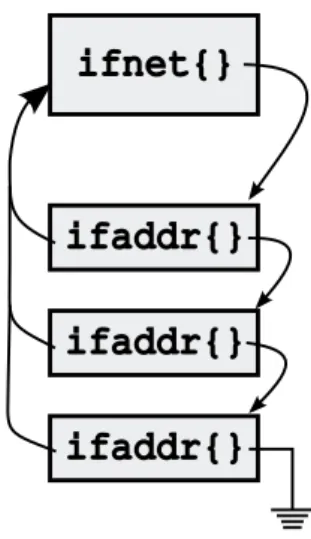
Besides dealing with transmission/reception of frames, device drivers take care of structure allocation: during kernel initialization data structures are allocated and attached to each other. Such as the ifnet structure which contains information common to all interfaces: implementation information (e.g. the name of the interface, its flags), hardware information (e.g. the hardware address type supported by the interface, the maximum transmission unit, the metric), interface statistics, function pointers and the output queue (the queue of outgoing packets for the interface).
ifnet{}
ifaddr{}
ifaddr{}
ifaddr{}
Figure 2.2: ifnet and ifaddr data structures.
During system initialization the kernel locates any attached network device and, for each one, a separate ifnet structure is allocated and initialized by the device driver. Then, the if attach() function is called to insert the structure into the linked list of interfaces. Moreover, every interface owns a linked list of ifaddr structure (namely the interface address structure). Every structure contains an address assigned to the interface, usually one per protocol.
The NIC handles packets using hardware circular queues (rings) containing the packet descriptors. In each packet descriptor the device driver stores information about network packets (e.g. physical address of the packet buffer, its length, flags).
The kernel deals with them using shadow copies of NIC rings: kernel buffers are arranged inside a list of OS-specific but device-independent con-tainers (mbufs, skbuf or NDISbuffer depending on the operating system). Packets are often fragmented into multiple mbufs: usually the first keeps track of the header, while the others are used for data.
sockbuf{} sb_mbuf m_next m_nextpkt m_next m_nextpkt m_next m_nextpkt m_next m_nextpkt mbuf{} m_next m_nextpkt NULL NULL
NULL NULL NULL
NULL mbuf{} mbuf{} mbuf{} mbuf{} First packet Second packet
Figure 2.3: Linked list of mbuf chains.
The software interface assumes that fragmentation can occur for ingo-ing/outgoing traffic, so both the device driver and the host stack must be prepared to handle it.
Kernel has to allocate mbufs individually, at run-time and it has to keep those lists organized: depending on amount of traffic, the overhead introduced by these operations overcomes the flexibility benefits of those structures.
2.2
Interrupt
When a frame is received by the network adapter, it is queued inside a FIFOi
(if it’s full, new frames will be dropped). Afterward, one frame is extracted from the FIFO and placed inside the operating system memory: at this point the network interface generates an interrupt and the kernel calls a routine to make it available to higher protocols stack layers.
Time packet arrival interrupt
a)
b)
Timeinterrupt interrupt interrupt
packet arrival packet arrival packet arrival packet arrival packet arrival
Figure 2.4: Comparison between single interrupt (figure a) and interrupt mitigation mechanism (figure b).
However this mechanism could be ‘‘too heavy’’, from a computational point of view, in a high-traffic scenario. This is the reason why NIC drivers implement a technique known as interrupt mitigation: the NIC won’t generate an interrupt for every frame it receives; instead, the hardware waits for more frames or a time out expiration before generating it. This way an overall system performance degradation is avoided.
On the other hand, this adds latency to the frames arrival time and, consequently, to the round-trip-time: even if the frame resides in the host memory, the host is not aware of it until some time later.
iFIFO stands for First In First Out and describes a technique for data storage and
It follows that protocols which intensely use acknowledgment messages (such as TCP ) are badly affected by interrupt mitigation.
2.3
Layer 2 and IP processing
Protocols of data link layer (the second among protocols stack layers) specify the format of packets exchanged between entities in a computer network along with the actions performed to send and receive them.
Services provided by data link layer may diverge from a protocol to another, here we’ll focus on the Ethernet protocol.
Ethernet is one of the most diffused data link protocol for local area networks (LAN), it is one of the implementations of CSMA/CDii.
Its frame consists of 48-bit destination and source physical addresses followed by a 16-bit type field that identifies the format of the data carried by the frame and it is terminated with a 32-bit CRCiii, which detects errors
in the frame.
An ethernet interface usually receives frames destined for its unicast physical address, for the ethernet broadcast address and, in case, for a multicast address.
The driver checks the CRC field of incoming frames (frames with a wrong CRC field will be discarded), afterward examines the ether header structure (which wraps frame information) to determine if the destination address is consistent with the physical address of the local interface and finally the type field, which is used to correctly queue received data for processing on the
iiCarrier Sense Multiple Access with Collision Detection is a network technology: every
node of such network is able to determine the medium state (idle or busy) and if a collision occurred during its transmission. In case, a retransmission will be scheduled.
higher layer.
Transmitter side creates ethernet frames and fills their fields according to its physical address, the target host one and with the type of the data carried inside it. After the encapsulation of the IP packet, sends it through the link (CRC field is usually computed in hardware by the NIC).
destination address
source
address type data CRC
type
0x800 IP packet
6 bytes 6 bytes 2 bytes
2 bytes 46-1500 bytes
46-1500 bytes 4 bytes
Figure 2.5: Ethernet encapsulation of an IP packet.
The translation from IP to physical addresses is done by the ARP protocol and from physical to IP addresses by the RARP protocol.
IP protocol is located in the upper layer (compared with data link one) of the protocols stack, the network layer ; it provides further services such as congestion notification and message fragmentation (when their size is grater than the MTUiv) performed breaking the datagram up into smaller pieces so
that each fragment is smaller than the MTU. IP processing involves only its header, it does not examine or modify the message itself.
Such header contains information about, besides fragmentation, the packet format, addressing and routing as shown in the picture below.
ivMaximum Transmission Unit : it represents the size of the largest protocol data unit
On reception, packets checksum is verified: if wrong, they are silently discarded. It’s computation affects only the IP header.
4-bit version
4-bit header length
8-bit type of service
(TOS) 16-bit total length (in bytes)
13-bit fragment offset 3-bit
flags 16-bit identification
8-bit protocol 16-bit header checksum
8-bit time to live (TTL)
32-bit source IP address
32-bit destination IP address
options (if any)
data
0 15 16 31
20 bytes
Figure 2.6: IP packet structure.
The next step is to check information included in the packet header: first of all the IP version (IPv4 or IPv6), then the logical address of destination. If packet has reached its final destination, it is passed to the appropriate transport-level protocol (the one specified in the protocol field).
When transmitting, IP deals with the packet creation and passes it to the data link layer protocol.
2.4
Socket processing
Above, in the protocols stack, we find the transport layer: there reside protocols, such as UDP, which use sockets to transmit/receive data.
A socket is a software endpoint for communications among processes across computer networks. In UDP transmissions, it’s formed by a unique combination of local IP address, process port and protocol; within operating systems a socket is referred by a unique number (namely its identifier ).
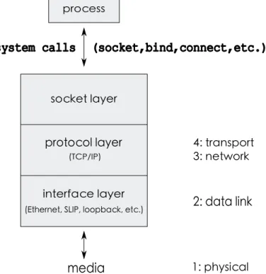
socket layer
protocol layer
interface layer
(Ethernet, SLIP, loopback, etc.) (TCP/IP)
media
1: physical 2: data link 4: transport 3: network processsystem calls (socket,bind,connect,etc.)
Figure 2.7: Socket layer and processes interaction.
The socket layer is a independent interface to the protocol-dependent layer below. All system calls start at the protocol-inprotocol-dependent socket layer.
Sockets provide an abstraction layer to map protocol-independent requests from a process to the protocol-specific implementation selected when the socket was created.
The transport layer deals with the encapsulation of a message provided by the application layer in a transport protocol packet (transmitter side) and, vice versa, its extraction (receiver side).
Most specifically, assuming the use of UDP transport protocol, we have to create a UDP socket containing the logical address of our network interface card and a valid port number (usually numbers from 0 through 1023 are reserved to well-known system services). Then, if we want to transmit, we have to add information about destination host (logical address and destination port) to the socket: when the UDP packet is created, the message is included in the payload and its header is filled with both source and destination ports, with its length (namely the number of bytes of header and payload) and the checksum computation. 20 bytes 8 bytes IP datagram UDP datagram IP header UDP
header UDP data
Figure 2.8: UDP encapsulation.
Checksum is performed over the payload, the UDP header and some IP header fields. The reason why IP fields are included, is to detect (hence discard) packets that have been routed to the wrong IP address.
checksum length destination port source port payload 0 32 0 - 15 16 - 31 64+
Figure 2.9: UDP packet structure.
On reception, the destination host verify the checksum and compare destination address and port with the information included in the socket. If they match, packet payload (along with address and port of the sender) is forwarded to the application layer, otherwise packet is discarded.
Chapter 3
The Netmap architecture
Performance of packet processing operations on general purpose OS are heavily limited by the design of Kernel protocols stack: its high flexibility in network operations comes at the expense of a considerable slowness due to the long journey of packets between the network adapter and the userspace application.
Netmapi is a novel framework that addresses such problem providing a direct, protected and fast access to network packets. Its peculiarity consists in the fact that it reduces the overhead of per-packet operations and avoids unnecessary copies between packets reception from the NIC and userland : clearly these are expensive operations and therefore they deeply affect the maximum obtainable throughput.
i
3.1
Network interfaces management
When in netmap mode, network interfaces are partially disconnected from the OS protocols stack: even though their management functions (which bring them up/down and control their attributes such as IP address, speed, maximum transmission unit, etc.) still work, we have access directly from userspace to device packets buffers and we can exchange them with the host stack using circular queues of buffers (namely the netmap rings) located in a shared memory area.
This is implemented through modifications directly into network device drivers: inside their loading function (attach) they are requested to initialize a netmap adapter structure that will be freed during unloading function (detach). num_rings ring_size cur len pkt_buf pkt_buf pkt_buf netmap_if{} netmap_ring{} NIC_ring{} ring_ofs[] avail flags buf_ofs flags index
Shared memory area
The structure stores multiple information regarding the NIC, such as the number of TX/RX queue pairs, the size of packet buffers along with the callbacks needed to accomplish common operations like acquire or release locks.
3.2
Wrapping structures
For each network device netmap provides three types of user-visible objects: 1. Netmap interface descriptors
2. Netmap rings 3. Netmap slots
Netmap interface descriptors are a lighter replica of Kernel structure ifnet, an object which stores every functions needed to set flags belonging to the corresponding network device.
They are returned by the Kernel every time an application ‘‘turns’’ a network device into netmap mode.
Netmap rings are representations of hardware-implemented circular queues and contain information such as:
• the total number of slots in the ring
• the number of available slots: while on the transmitter side it means the number of empty slots, on the receiver one it’s the number of slots containing readable packets
• a status flags for special conditions
• the address pointer to the memory area where packet buffers reside • the size of packet buffers
Netmap rings consist of netmap slots, containers for received/transmit-ted packets: they include, as well as the packet buffer itself, the buffer index, the packet length (it may differs from the slot one) and flags which describe its status.
3.3
Structures synchronization
Providing to userspace shadow copies of NIC queues (netmap rings), rises synchronization concerns. This problem was handled using reference counters between userspace and Kernel.
Synchronization itself is performed through powerful system calls
(ioctl() and poll()), this ensures that only one thread or process is working on the same object at the same time.
Moreover, processes using netmap cannot cause a system crash because shared memory area does not contain critical memory regions and buffer indexes/length must be validated by the Kernel before being used.
3.4
Netmap API
Every userspace program which intends to put a network interface card into netmap mode needs to open the special device /dev/netmap and then issue an ioctl() on its file descriptor:
f d = open (''/dev/netmap'' , . . . ) ; i o c t l ( fd , NIOCREGIF, a r g ) ;
Each object for all netmap enabled devices, resides in a large memory region, allocated by the Kernel in a non-pageable area and shared by all user processes.
For this reason userspace applications have to get the size of the pre-allocated memory usable by netmap devices issuing an ioctl() and then a mmap() system call in order to work with the aforementioned netmap data structures:
i o c t l ( fd , NIOCGINFO, a r g ) ;
addr = mmap( fd , . . . , me mo ry si ze , . . . ) ;
Transmission and reception are handled by means of two ioctl() calls: programs in needs to transmit packets have to fill up available buffers in transmit rings and issue the synchronization ioctl():
i o c t l ( fd , NIOCTXSYNC, NULL ) ;
This system call tells the system about the availability of new packets to transmit; also, slots filled with packets previously sent are freed by netmap drivers, so they can be used again by userspace applications.
Regarding the receive side, programs have to issue an ioctl() to notice how many packets are available to read:
i o c t l ( fd , NIOCRXSYNC, NULL ) ;
This will also update packets information (such as payload content and length) inside netmap slots.
The previously described ioctl() calls are non-blocking, they don’t involve data copying (except for synchronization of netmap slots) and can deal with multiple packets at once. These are key features to considerably reduce per-packet overhead.
3.5
Blocking primitives
Blocking I/O support is provided with select() and poll() system calls: userspace program will be awoken when the netmap file descriptor is ready to be read/written (when there are available slots in Rx/Tx netmap rings). Before functions return, as with non-blocking ioctl(), netmap drivers will update the status of the rings.
Chapter 4
Performance of the IP and
UDP stack
In order to get an overview on FreeBSD protocols stack performance, we ran a bunch of tests trying to figure out which factors concur to the throughput maximization.
4.1
Test application: nuttcp
For our tests we made use of nuttcpi, a free opensource software (version 6.1.2
at the time of this writing) capable of several kind of network performance measurements.
Most specifically we are interested in UDP transmissions and to keep track of the number of I/O calls (sendto() and recvfrom()) per second (hence the throughput ), CPU utilization, buffer length (namely the payload size of UDP packets), number of dropped packets by the receiver (data loss percentage).
i
The program uses synchronization signals, sent by the source host, to define a time interval of intense data exchange: at the beginning sender transmits two special packets with payload equal to ‘‘BOD0’’ and ‘‘BOD1’’ (Begin Of Data), destination host will check the payload of these two packets
before the start of the receiving loop.
BOD1 BOD0 Data transfer
Sender
Receiver
EOD0 EOD3 EOD1 EOD2 EOD4 Receiver statisticsStart
Finish
Figure 4.1: Message passing during UDP instances of Nuttcp.
At this point both sender and receiver take a timestamp and the trans-mission begins, the test duration was been set when launching nuttcp.
Afterward, the sender will transmit packets with the special payload ‘‘EODx’’ (End Of Data) to report the end of transmission to the receiver:
hence, both sender and receiver will take a second timestamp.
The application, during its functioning, uses a separate TCP channel (like a control connection) to transmit statistics and commands between hosts.
Statistics about the test are then calculated separately by source and destination hosts and displayed on the screen.
4.2
Discuss of bottlenecks
First, in order to understand the overhead introduced by such program, we ran some tests with modified transmission and reception functions so as to bypass the system calls (hence no packets are sent/received): this way the only code executed was the one in nuttcp program and we could estimate its ‘‘cost’’.
Calls number per second Sender-side 20,025,000
Receiver-side 80,000,000
It follows that nuttcp code is executed for about 50 ns for each system call during transmission and for 12.5 ns during reception: this is because transmitter side application has to issue poll operations to check the TCP channel for urgent messages from the receiver.
Tests are performed setting packet size to the minimum value (60 bytes + 4 bytes Ethernet CRC): this emphasizes the ‘‘per-packet ’’ cost, an evaluation of the unavoidably overhead during packets transmission.
Frequency and number of active cores of the CPU have been varied to measure the system behaviour at different stress conditions and understand in which case overall performance are CPU-limited.
Moreover, even if the 10 Gbit NICs used for the tests are equipped with 4 hardware rings, during nuttcp functioning only one of them will be involved due to the Receive-Side Scaling: it is a hardware mechanism implemented
by modern network adapters to decide the destination hardware ring for incoming packets. Usually it is based on a hash value computed on specific header fields (e.g. IP address, port, protocol) which in our case are constant.
4.3
Test equipment
Tests were run between two machines equipped with the following hardware configuration:
• dual port 10 Gbit/s card based on the Intel® 82599 chipii mounted on
a PCIe-x16 slot (8 lanes are used by the NIC)
• Intel® i7-870 CPUiii (4 cores) running at a top speed of 2.93 GHz
(3.2 GHz when Intel® Turbo Boostiv is active)
• 4 GB of RAM
• FreeBSDv 10.0-CURRENT (December 2011) operating system
iiIntel® 82599 10 Gigabit Ethernet Controller: http://ark.intel.com/products/
32207/Intel-82599EB-10-Gigabit-Ethernet-Controller
iiiIntel® Core™ i7-870 Processor (8M Cache, 2.93 GHz): http://ark.intel.com/
Product.aspx?id=41315
ivhttp://www.intel.com/content/www/us/en/architecture-and-technology/
turbo-boost/turbo-boost-technology.html
v
4.4
Test results
The figure 4.2 shows the system call number performed by the receiver (equipped with a 10 Gbit/s NIC) with the standard library on FreeBSD.
0 2e+05 4e+05 6e+05 8e+05 1e+06 1.2e+06 0 500 1000 1500 2000 2500 3000 3500 Throughput (pps) CPU frequency (MHz) 1 core 4 cores
Figure 4.2: Receiver throughput on a 10 Gbit/s link.
The two curves appear to be nearly linear, yet there’s a great difference between the performance obtained by the multicore configuration and those obtained by the single core: the maximum throughput achieved with 4 cores is about 1.070 Mppsvi, while with 1 core the receiver reaches only 0.615 Mpps
at the maximum clock speed.
10 Gbit/s - UDP reception - 18 bytes buffer
CPU frequency 1 core 4 cores
(GHz) (Mpps) (Mpps) 0.150 congested 0.057 0.300 congested 0.122 0.600 congested 0.242 0.750 congested 0.307 1.050 congested 0.440 1.200 0.002 0.511 1.333 0.030 n/a 1.467 0.058 0.621 1.600 0.080 0.679 2.000 0.187 0.794 2.267 0.247 n/a 2.533 0.345 0.874 2.667 0.392 n/a 2.934 0.491 1.066 3.200 0.615 1.077
As previously said, for every packet (or a group of them if interrupt mitigation is active) received by the NIC an interrupt is risen and a thread (in kernel space) is started to handle it. This thread has a higher priority
than the system call process in userspace.
For this reason in a high incoming traffic scenario with only one core available, almost all of the CPU resources will be consumed by the kernel space thread.
With four active cores, otherwise, the computation is split: one core handles the kernel space thread while another one will handle the userpace process.
Moreover when the CPU frequency is lower than 1200 MHz and with a single core active, the receiver is fully congested. In this case the network
adapter can use only one hardware ring and probably for this reason it cannot decently cope with intense data transfer peaks.
Regarding the transmitter side, both configurations (1 core and 4 cores) have a linear progress and appear to be CPU-limited : the multicore setting reaches better performance at each step with a maximum value of 0.614 Mpps at 3.2 GHz. 0 2e+05 4e+05 6e+05 8e+05 500 1000 1500 2000 2500 3000 3500 Throughput (pps) CPU frequency (MHz) 1 core 4 cores
Figure 4.3: Transmitter throughput on a 10 Gbit/s link.
10 Gbit/s - UDP transmission - 18 bytes buffer
CPU frequency 1 core 4 cores
(GHz) (Mpps) (Mpps) 0.600 0.057 0.123 1.050 0.100 0.214 1.600 0.193 0.325 2.000 0.269 0.384 2.533 0.376 0.488 2.934 0.459 0.574 3.200 0.575 0.614
This time the difference between single and multicore throughput value is lower. Interrupts during transmission are risen only when a packet is sent. Therefore, even with a single core active, the kernel space thread which handles those interrupts cannot keep running if the userspace process is blocked due to the priority mechanism.
Chapter 5
A fast userspace UDP stack
Netmap, at the current version, doesn’t provide a native UDP interface to transmit and receive packets. Programs in need to send UDP messages have to build raw packets themselves and put them into netmap rings.
We aim to build such UDP interface through the emulation of the stan-dardi transmission/reception functions:
• socket() • close() • bind() • connect() • send() • sendto() • recvfrom()
Clearly we want to avoid, as much as possible, every unnecessary operation (especially buffer copies) which can be responsible for huge performance losses.
5.1
Architecture
Instead of using system calls we designed a layer whose task is to emulate their running without affecting on the throughput in a negative way.
Application
Netmap UDP layer Tx
UDPmessage
Net
NIC
Netmap NIC ring
sendto()
UDP packet
Figure 5.1: Functional schema of sender host.
We have maintained the same API interface of standard system calls as well as the functional behaviour: applications in need to send messages must, first of all, create a socket (in our case a pseudo one, as it will be illustrate later), link it to a specific destination host (adding its information to the socket) and then provide a message to the send function.
On the other hand, applications interested in reception, after the socket creation have to bind it with an address and a valid port number. Hence provide a buffer (for the received message) to the receive function.
Stack
Netmap UDP layer Rx
Net
Application
NIC
Netmap STACK ring
Netmap NIC ring
Not UDP packet
recvfrom()
UDP message UDP packetFigure 5.2: Functional schema of receiver host.
As mentioned above, when in netmap mode the network interface is partially disconnected from the protocols stack: for this reason when we designed the UDP layer of the receiver, we took care of forwarding packets not belonging to the UDP traffic to the stack.
This allowed us to manage ARP mechanism: when the receiver is awaiting for UDP packets, it is blocked on the function nm recvfrom() and the sender could transmit an ARP request. In this case the netmap UDP layer will provide to forward such request to the protocols stack and, afterward, it will transmit back to the sender the ARP response built by the stack.
Something similar happens when the sender tries to transmit a message to an unknown host (its physical address is not present among either socket information nor the ARP table), it is blocked on the function nm sendto(). Our layer will provide to send an ARP request packet and to handle the reply adding destination physical address to the socket and forwarding it to the stack.
5.2
Socket management
We made use of a pseudo socket which, in our case, is a data structure containing information needed to transmit/receive messages such as:
• physical/logical addresses and ports of source and destination hosts • wrappers for IP and UDP headers
• checksum computation of constant fields of IP and UDP packet headers: since they don’t change during the transmission we can pre-calculate their checksum and, later, add it to the one for variable fields; this
allows us to save a lot of time for every packet directed to the same destination host
• packet dimension
• pointers to netmap rings and netmap file descriptors (for both the network interface card and the protocols stack)
• information about netmap rings (e.g. ring size, indexes of first and last slot, flags)
• IP packet id (which is updated every transmission)
To create a socket, the host has to issue a nm socket(): the structure is allocated and, part of it, will be initialized (e.g. packet dimension is set to the MTU of the network interface associated to netmap).
During sockets initialization process the network interface is put into netmap mode and we gain gain access to the shared memory region where netmap data structures are located (as explained in chapter 3).
Socket closure is performed issuing a nm close socket(): the network interface status is restored (it is reconnected with the protocols stack) and socket data structure is freed.
5.3
Transmit functions
The task of function nm sendto() is to build a UDP packet filled with the user supplied payload and transmit it through the NIC as fast as possible.
As previously said, we want to keep things as agile as we can, minimizing the number of instructions per I/O call.
When nm sendto() is called, the structure containing destination host address and port (provided by the userspace application) is checked with the information stored in the socket: if they don’t match, nm connect() is issued.
Here the ARP table is queried, looking for the physical address of the destination host: if not present an ARP request packet will be sent awaiting for the reply. When received, destination MAC address will be copied inside socket and the reply forwarded to the protocols stack.
i n t
nm sendto ( s t r u c t p s e u d o s o c k e t ∗ sock , const void ∗ b uff e r , int buf len ,
const s t r u c t s o c k a d d r ∗to , s o c k l e n t t o l e n ) { . . . i f ( d e s t i n a t i o n u n k n o w n ( to , t o l e n ) ) nm connect ( s o c k , to , t o l e n ) ; b y t e s s e n t = nm send ( so c k , b u f f e r , b u f l e n ) ; return ( b y t e s s e n t ) ; }
While the sender is waiting the reply, every packet coming from the stack is forwarded to the NIC and same happens for packets coming from the NIC.
Once address is obtained, we can start to fill constant fields of packet header (still inside nm connect()), checksum pre-computation is performed and the result is stored in the socket: this computation will spare us a tremen-dous amount of time for transmissions which involve the same destination.
i n t
nm connect ( s t r u c t s o c k e t ∗ sock ,
const s t r u c t s o c k a d d r ∗name , s o c k l e n t namelen ) { . . . i n i t i a l i z e c o n s t h e a d e r ( s o c k ) ; // v a r i a b l e f i e l d s // a r e e r a z e d /∗ p o i n t e r to the f i r s t header f i e l d ( IP and UDP h e a d e r s a r e c o n t i g u o s ) ∗/ p = ( u i n t 3 2 t ∗) &sock−>header ; /∗ IP constant f i e l d s computation ∗/
s o c k−>i p c o n s t c h e c k s u m = CKSUM REDUCE( p [ 0 ] + p [ 1 ] + p [ 2 ] + p [ 3 ] + p [ 4 ] ) ;
/∗ UDP constant f i e l d s computation ∗/
s o c k−>u d p c o n s t c h e c k s u m = CKSUM REDUCE( p [ 3 ] +
p [ 4 ] + p [ 5 ] ) ; return ( 0 ) ;
Application
Stack
Netmap UDP layer Tx
Net
NIC
Netmap STACK rings
Netmap NIC rings
ARP reply get_ARP_reply() sendto() STOP ARP request send_ARP_request()
Figure 5.3: ARP management during transmission.
Clearly nm connect() will be issued only for unknown destinations: if target physical address is present inside pseudo socket, ARP mechanism won’t be triggered off.
After that, variable fields in packet header are filled with proper values; also, their checksum is computed (inline) and added to the one stored in the socket.
i n t
nm send ( s t r u c t p s e u d o s o c k e t ∗ sock , const void ∗ bu f f er , int b u f l e n ) { . . . /∗ f i l l packet header v a r i a b l e f i e l d s ∗/ . . . p o l l f d . f d = s o c k e t −>n e t m a p N I C f i l e d e s c r i p t o r ; p o l l f d . e v e n t s = POLLOUT; f o r ( ; ; ) { i f ( p o l l (& p o l l f d , . . . ) ) { f o r ( i = f i r s t ; i <= l a s t ; i ++) { r i n g = g e t r i n g ( i ) ; i f ( r i n g −>a v a i l > 0 ) { c u r = r i n g −>c u r ; s l o t = &r i n g −>s l o t [ c u r ] ; /∗ headers copy ∗/ memcpy(& s l o t −>b u f f e r , &s o c k−>h e a d e r s , h e a d e r l e n ) ; /∗ payload copy ∗/ memcpy(& s l o t −>b u f f e r , b u f f e r , b u f l e n ) ; /∗ update r i n g indexes ∗/ return ( b u f l e n ) ; } } } } }
Now the packet is ready to be sent, when the poll() returns we know there are available slots for transmission in netmap rings: one of them is filled with our packet and indexes of the netmap ring (current slot and the number of available slots) are updated.
5.3.1
Checksum
The heaviest operations are certainly those involved in checksum computation. Our UDP stack implementation supports checksum computation for both IP and UDP headers: every packet sent needs to be filled with that information.
In order to do it efficiently, the sum of constant fields (IP version, IP header length, type of service, flags, offset, time to live, protocol, source/destination logical address, UDP source/destination ports) of both IP and UDP headers is performed during packet header creation in the function nm connect().
data
options (if any) 32-bit destination IP address
32-bit source IP address 8-bit time to live
(TTL) 8-bit protocol 16-bit header checksum
16-bit identification flags3-bit 13-bit fragment offset
16-bit total length (in bytes)
8-bit type of service (TOS) 4-bit header length 4-bit version 0 15 16 31 0 32 64 96 128
source port destination port
length checksum
payload
0 32
0 - 15 16 - 31
Figure 5.4: IP and UDP headers constant fields.
For every new packet we want to transmit, we only have to add values of variable fields (IP length, IP packet id, UDP length and UDP pseudo-header ) to the checksum, stored in the pseudo socket.
We have tested the performance of three algorithm for the checksum computation: the first one sums 16-bit chunks of data in a 32-bit accumulator; the second one sums 32-bit chunks in a 64-bit accumulator; the last one (32* sum in the table below) makes a conversion to 64-bit before performing the sums of 32-bit chunks in a 64-bit accumulator.
Looking at the results, it seems that the compiler takes advantage of this conversion and is able to perform faster sum operations.
Buffer length 16 sums 32 sums 32* sums (bytes)
128 0.067usec 0.033usec 0.032usec 256 0.098usec 0.058usec 0.056usec 512 0.185usec 0.141usec 0.103usec 1024 0.360usec 0.273usec 0.198usec 2048 0.711usec 0.536usec 0.388usec
Tests were done taking one timestamps before and one right after a loop of 100 millions computations: this way the time spent to take timestamps (with the function gettimeofday()) is nearly wiped out by the great number
of iterations.
Clearly the last algorithm (32* sum) has been chosen for the computation in our layer.
5.3.2
Encapsulation
As in the TCP/IP protocol suite, packets are built using encapsulation: the content of the higher layer message is enclosed as the data payload of the message at the lower layer as shown below.
Frame
header Frame data
Frame trailer IP header IP payload UDP payload UDP
header UDP Layer
IP Layer
Ethernet Layer
Application Layer
message
Figure 5.5: Graphical representation of encapsulation mechanism.
Every layer adds information to the data by prepending headers (and sometimes appending trailer information) to the data that it receives; more-over, it will use the information included in the corresponding header to correctly deliver messages to recipients and forward the payload to the higher layer.
In this case UDP datagrams becomes the payload for IP packets, whereas IP packets are inserted in ethernet frames.
5.4
Receive functions
The function nm recvfrom() returns the first UDP packet, addressed to the local host, found in netmap NIC rings.
Besides, it updates a structure provided by the caller-application, with information concerning the sender host.
5.4.1
Selection
While awaiting for UDP packets, receiver host has to behave like a network bridge: every other kind of packet found will be forwarded to the protocol stack (if coming from the NIC) and, vice versa, those coming from the stack will be forwarded to the NIC.
This is realized using two netmap file descriptors: one for the NIC, the other for the stack which, in this case, is seen as a software network interface with software netmap rings mapped in the shared memory area.
Packet forwarding is made simply exchanging slots between netmap rings associated with the stack and those associated with the NIC: such exchange is nothing but a slot index swap, no copy operation on netmap slot buffers is performed.
Acting like this we can support ARP mechanism as well: while awaiting for a UDP packet, host may be the target of an ARP request ; if so ARP request packet will be forwarded to the protocol stack, which will send back an ARP reply containing the physical address of the NIC (figure 5.6).
We noticed that when we were scanning NIC rings, looking for a valid UDP packet, a lot of time was wasted.
i n t
nm recvfrom ( s t r u c t s o c k e t ∗ sock , void ∗buf , int len , s t r u c t s o c k a d d r ∗from , s o c k l e n t fromlen ) { s t r u c t p o l l f d p o l l f d [ 2 ] ; // 0 : s t a c k − 1 : NIC . . . f o r ( ; ; ) { i f ( r i n g s a r e e m p t y && n o s l o t e x c h a n g e b e t w e e n N I C a n d s t a c k ) { i f ( p o l l ( p o l l f d , 2 , 1 0 0 ) <= 0 ) continue ; } /∗ check STACK r i n g s ∗/ i f ( p o l l f d [ 0 ] . r e v e n t s & POLLIN) {
/∗ forward packets to the NIC ∗/
. . . }
/∗ check NIC r i n g s ∗/
i f ( p o l l f d [ 1 ] . r e v e n t s & POLLIN) {
/∗ forward not UDP packets to the stack ,
r e t u r n UDP p a c k e t p a y l o a d ∗/
. . . }
} }
Stack
Netmap UDP layer Rx
Net
Application
NIC
Netmap STACK ring
Netmap NIC ring
recvfrom() STOP ARP reply ARP request
Figure 5.6: ARP mechanism management, receiver side.
For this reason we have optimized this process adding to the socket structure the index and the available slots number of the ring where the last UDP packet was found: most probably, the next one will reside in there.
. . . i f ( s o c k e t −>l a s t f o u n d a v a i l > 0 ) r i n g i n d e x = s o c k e t −>l a s t f o u n d i d x ; e l s e r i n g i n d e x = end = f i r s t r i n g ; /∗ s c r o l l r i n g s s t a r t i n g from r i n g i n d e x ∗/ . . .
Polling file descriptors is another expensive operation, therefore we have to limit the poll() number as much as possible: it is needed only if stack and NIC rings are empty (thus there is no packet to receive), or when a slot exchange occurred and is necessary a synchronization of rings.
Before returning the UDP message to the userspace application, header of the received packet needs to be checked: physical/protocol destination addresses, UDP destination port, ethernet type, IP protocol type, IP/UDP lengths and checksums.
In order to increase the speed of our application, we used software prefetch-ing technique to reduce cache miss lantency. Durprefetch-ing netmap rprefetch-ings scan, we have to analyze every packet found and determine whether or not it is a UDP one: when many of them are present in the ring, execution of verification code on packets header (which reside in memory) rises a lot of cache misses.
Software prefetching is used to move data (in our case the packet header) closer to the CPU cache, limiting cache miss number when header fields are checked.
. . .
char ∗ pkt = NETMAP GET PACKET( nm ring , b u f f e r i n d e x ) ; p r e f e t c h ( pkt ) ;
/∗ check packet header ∗/
i f ( c h e c k i f u d p ( s o c k , pkt , p k t l e n ) ) g e t p a y l o a d ( pkt ) ;
. . .
If the packet header gets through every verification, the UDP payload is returned to the application. This is the only copy of the buffer made, as previously said copy operations are expensive (in terms of performance) and, when unnecessary, they should be avoided.
5.4.2
Checksum
Similarly to what happens on transmission side, again on reception one checksum computation (mostly the UDP one) plays a key role to obtain high performance.
Moreover this time we cannot pre-calculate part of it, since there are no constant fields: this is one of the reasons why the receiver throughput will be lower than the transmitter one.
As before, the checksum computation is performed with inline functions, which grant higher performance.
5.5
Interaction with the host
Applications in need to send UDP messages, have to behave as with standard transmission/reception functions.
First of all they have to create a pseudo socket issuing a nm socket(). Specifically they have to specify, among others, the interface name netmap will use:
s t r u c t s o c k e t ∗ sock = nm socket (''if name'' , prot fa mily , UDP) ;
Then, if interested in transmission, they have to issue a nm sendto() providing the message buffer and information about destination host (its IP address and UDP port):
i n t num bytes = nm sendto ( s o c k , b u f f e r , b u f l e n ,
d e s t i n a t i o n i n f o , d e s t i n f o l e n ) ;
As previously said, inside nm sendto(), will be executed the function nm connect() which associates the socket with a destination host. Hence an application, instead of directly use nm sendto(), could issue itself a nm connect() followed by calls to nm send() functions:
nm connect ( s o c k , d e s t i n a t i o n i n f o , d e s t i n f o l e n ) ; i n t num bytes = nm send ( s oc k , b u f f e r , b u f l e n ) ;
. . .
i n t num bytes = nm send ( s oc k , b u f f e r , b u f l e n ) ;
On the other hand, if the application is interested in reception, after the socket creation must issue a nm bind() in order to associate it with an IP address and a port number (which will be used by the sender).
Now receiver can issue a nm recvfrom() providing a buffer where the message will be placed; message length (in bytes) will be returned as well.
nm bind ( s o c k , a d d r p o r t , a d d r p o r t l e n ) ;
i n t num byte = nm recvfrom ( s o c k , b u f f e r , b u f f l e n , from , f r o m l e n ) ;
Besides, a user provided structure is updated with IP address and port of sender socket.
Finally both sender and receiver need to perform socket closure issuing a nm close socket().
n m c l o s e s o c k e t ( s o c k ) ;
This will cause a deallocation of the netmap instance and the network adapter will return to the original state, hence connected with the protocol stack.
5.6
Performance
As before, to perform our tests we used the open source application nuttcp (whose running is described in section 4.1): we have modified it so that it will
call netmap UDP layer functions instead of standard library system calls. The figure 5.7 shows the throughput of the receiver on a 10 Gbit/s link: the curves have a nearly linear progress with a maximum throughput value of 5.2 Mpps for the single core configuration and 4.8 Mpps for the multicore one; besides it seems to be CPU-limited.
Netmap UDP layer with a CPU frequency of 750 MHz is faster than the standard library at the maximum clock speed, while at 3200 MHz it is more than 3 times faster.
0 1e+06 2e+06 3e+06 4e+06 5e+06 6e+06 0 500 1000 1500 2000 2500 3000 3500 Throughput (pps) CPU frequency (MHz) 1 core 4 cores
Figure 5.7: Netmap UDP receiver on a 10 Gbit/s link.
10 Gbit/s - netmap UDP receiver - 18 bytes buffer
CPU frequency 1 core 4 cores
(GHz) (Mpps) (Mpps) 0.450 0.743 0.771 0.750 1.247 1.297 1.050 1.747 1.828 1.333 2.233 2.339 1.600 2.695 2.815 2.000 3.176 3.299 2.267 3.480 3.600 2.533 3.735 3.858 2.934 4.436 4.571 3.200 5.204 4.855
The transmitter curves have a linear progress as well. The maximum throughput reached is about 10 Mpps (almost 20 times greater than the standard library system calls); with the CPU working at 300 MHz netmap transmitter has a greater throughput than the standard library version at the maximum clock speed. Besides, it appears to be CPU-limited.
0 2e+06 4e+06 6e+06 8e+06 1e+07 1.2e+07 0 500 1000 1500 2000 2500 3000 3500 Throughput (pps) CPU frequency (MHz) 1 core 4 cores
Figure 5.8: Netmap UDP transmitter on a 10 Gbit/s link.
10 Gbit/s - netmap UDP transmitter - 18 bytes buffer CPU frequency 1 core 4 cores
(GHz) (Mpps) (Mpps) 0.150 0.434 0.451 0.300 0.926 0.945 0.750 2.401 2.437 1.050 3.388 3.434 1.333 4.344 4.393 1.600 5.146 5.217 2.000 6.363 6.458 2.267 7.134 7.259 2.533 7.880 7.986 2.934 8.934 9.058 3.200 10.498 9.700
This gap between netmap transmitter and receiver is partially caused by the different management of the checksum computation: while the transmitter takes advantage of constant header fields pre-calculation, the receiver is unable to exploit it.
Moreover the bridge-like behavior has a large impact on its performance: the receiver wastes a lot of time checking netmap stack rings for incoming packets to forward to the NIC and, besides that, looking for a valid UDP packet in netmap NIC rings.
From our measurements results that at a clock speed of 2934 MHz the average execution time of the nm recvfrom() is about 0.2 microseconds: half of this time (nearly 0.09 microseconds) is spent from the function beginning to the slot retrieval, the rest of it is used for the packet header verification and the copy of the payload.
Both multicore and single core configurations are involved in our tests in order to ensure a comparison between netmap and the standard library. However, due to the missing support for multi-processes execution, their performance are nearly the same.
Chapter 6
Conclusions
The huge overhead introduced by packets processing inside protocols stack layers strongly limits network performance on modern OSes.
4 cores Throughput RX (10 Gbit/s link) 1 core Standard library Netmap UDP layer
+350%
+746%
netmap
netmap
Figure 6.1: Performance enhancement of Netmap UDP receiver on a 10 Gbit/s link (CPU running at 3200 MHz).
We have implemented a UDP layer for the framework Netmap keeping the same interface of the standard library, reducing per-packet overhead and avoiding unnecessary copies of the packets buffer.
Packets processing has been streamlined: the netmap layer can access directly to NIC rings and returns to userspace UDP messages (or inserts UDP datagrams) without passing through the protocols stack.
This allowed us to considerably improve the throughput both in transmis-sion and in reception (as shown by figures 6.1 and 6.2).
4 cores Throughput TX (10 Gbit/s link) 1 core Standard library Netmap UDP layer
+1726%
+1480%
netmap
netmap
Figure 6.2: Performance enhancement of Netmap UDP transmitter on a 10 Gbit/s link (CPU running at 3200 MHz).
Moreover, the layer design permits ARP mechanism management: by necessity the transmitter is capable of sending, to the destination host, an ARP request; the receiver is able to receive ARP requests and to send back ARP reply packets.
Bibliography
[1] 10 Gbit/s Line Rate Packet Processing Using Commodity Hardware: Survey and new Proposals, L. Rizzo, L. Deri and A.Cardigliano
[2] netmap: a novel framework for fast packet I/O, L. Rizzo
[3] netmap: Memory Mapped Access To Network Devices, L. Rizzo and M. Landi
[4] netmap: fast and safe access to network adapters for user programs, L. Rizzo, 2011
[5] Design and implementation of a framework for very fast access to network devices, M. Landi, 2011
[6] TCP/IP illustrated (vol 1): the protocols, W.R. Stevens, 1994 [7] TCP/IP illustrated (vol 2): the implementation, W.R. Stevens
and G.R. Wright, 1995
[8] Computer Networking: A Top-Down Approach, J.F. Kurose and K. Ross, 2005