POLITECNICO DI MILANO
Facoltà di Ingegneria dei Sistemi
Corso di Laurea Specialistica in Ingegneria Biomedica Facoltà di Ingegneria dei Sistemi
Dipartimento di Bioingegneria
Tesi di Laurea Specialistica
A new system for tailoring and monitoring mechanical
ventilation by a wearable device at home
Relatore: Prof. Raffaele Dellacà Tutor: Dr. Leonardo Govoni
Tesi di Laurea specialistica di : Domenico Vito Matr n°: 721946
Pro veritate
adversa diligere…
Acknowlegements
So here the end of this adventure has come.Many faces and many friend I had the opportunity to know during these years.To each one of them I would to thank because each one of them gave me something that today represents my baggage of experience and emotions. To my college-mates of the firsts years, Mari, Guido, Dori, Stella, Giò, Fede,Terruz the Biglie! Thanks because with you started and shared this opportunity. To my friends of ever, Ale, Mauro, Nistro, Ricky, Cla, Andre thanks to have eaten my best “Friggione” been shared your days of study, your spare time with me…thanks for all the time spent together among serious matters, semi-serious matters and obviously funny things.
To my friends the volunteering experience who had left me a great sign in my life Carmine, Lucia, Betta, May, Chiara, Paulo, Enni, Fiammetta, Rosella, Fabio, Fausta, Erica, Daniela, the guys of CUMES and of the GCN and all the guys around Italy I have met. To my ”music friends” Aldo, Simo, Fhez, Giack, Chris(Luca) the Absinthe to have been shared such a great passion with me in these years.
To my friends of Cesano Anto, Fra, Claudio, Gianni e Anna e the Koinè’s guys….I can’t cite you all! Thanks for have always been beside me, for all the things we have done together.
In this last year probably the most hard and challenging I would to thank who accompanied me in this last step, and even who had supported me from far away sharing emotions and feelings. Thanks to TBM Lab Guys Giò e Dario, Pasquo, Ema e Ale for their fundamental advices, Ila e Chiara V. , Barbara, Marianna e Chiara G. with their help of “college-mates” and their politeness, Cynthia for her enthusiasm and freshness.
Thanks to prof. Dellacà and Leo for their constant support to this work.
And obviously thanks to my family that cared me, supported and carried me in these years mom, dad, my great bro Gio (great really great!), my cousins and my aunts…surely my greater gratefulness is for you..Because you, most of others, have make possible for me to get here, and for all thousand reasons that only one thesis would be enough to explain. I will be forgot someone for sure…but only on these pages and not inside me.
Ringraziamenti
Ecco finiti gli anni di questa grande avventura
Mille volti, mille facce mille amici ho conosciuto incontrato e vissuto.
Ad ognuno di loro vorrò dire grazie perchè ognuno di loro mi ha lasciato qualcosa, quel qualcosa che oggi rappresenta il mio bagaglio di esperienze e di emozioni.
Agli amici dei primi anni Mari, Guido, Dori, Stella, Giò, Fede,Terruz, le Biglie! grazie anche se non ci vediamo da molto: siete stati i primi compagni di viaggio con cui ho condiviso questa esperienza
Agli amici di sempre Ale, Mauro, Nistro, Ricky, Cla, Andre grazie per aver assaggiato i miei “Friggioni”, per aver condiviso le giornate in biblioteca, le uscite ecc....grazie per i momenti passati insieme tra cose serie, semiserie…e assolutamente poco serie!.
Agli amici del volontariato che hanno lasciato una forte impronta nella mia vita Carmine, Lucia, Betta, May, Chiara, Renata, Paulo, Enni, Fiammetta, Rosella, Fabio, Fausta, Erica, Daniela, i ragazzi/e del CUMES, il ragazzi/e del GCN e tutti i ragazzi/e in giro per l'Italia che ho incontrato.
Agli amici della “musica” Aldo, Simo, Fhez, Giack, Chris(Luca) e gli Absinthe per aver condiviso con me in questi anni una grande passione.
Agli amici di Cesano Anto, Fra, Claudio, Gianni Anna e di Koinè ..non vi elenco sennò non finisco piu! Grazie per esserci sempre stati e per tutto ciò che abbiamo fatto insieme.. In quest'ultimo anno, quello forse più faticoso e più intenso devo dire grazie ad altre tante persone che mi hanno accompagnato in questo ultimo passo, anche a chi da lontano ha condiviso con me gioie e dolori, lunghe chiacchierate e profonde emozioni .
Grazie ai ragazzi del TBM Lab, Giò e Dario Pasquo, Ale e Ema con i loro indispensabili consigli, Ila e Chiara V. , Barbara, Marianna e Chiara con il loro apporto da “compagni di corso” , Chiara G. con la gentilezza e suoi racconti fantastici, Cynthia con il suo
entusiasmo e la sua freschezza.
Grazie al prof. Dellacà e a Leo per il loro costante supporto in questo lavoro…
E ovviamente un grazie particolare alla mia famiglia che mi ha assistito, supportato e sopportato in questi anni mamma, papà e il mio “grande fratello” (nel senso che è veramente un grande) Giò, Nonna, i miei zii e miei cugini...di certo la gratitudine più
grazie…..perché avete voi più di tutti avete reso possibile che arrivassi fino a qui e per mille motivi che non basterebbe una tesi a spiegare...
Avrò dimenticato sicuramente qualcuno...nelle righe di queste pagine ma non sicuramente dentro di me
Contents
List of figures ... 8 List of Tables ... 12 Sommario ... 13 Abstract ... 14 Introduzione ... 15Chapter 1 - Anatomy, physiology and pathologies of the respiratory system ... 18
1.1 Introduction... 18
1.2 Anatomy of the human respiratory system... 21
1.2.1 Upper Airways: nose, mouth, pharynx and larynx... 22
1.2.2 Lower Airway: trachea, bronchi, alveoli... 23
1.2.3 The lungs... 25
1.3 Physiology of respiration ... 27
1.3.1 The act of breathing ... 27
1.3.2 Air diffusion ... 29
1.3.3 Mechanics of respiration... 33
1.3.1.1 Lung volumes... 34
1.3.1.2 Pressures... 35
1.3.1.3 Pressure-Volume curve in static conditions... 36
1.3.1.4 The electrical model of the respiratory system... 41
1.3.4 Nervous control of respiration ... 42
1.4 Respiratory disorders ... 45
1.4.1 Chronic obstructive pulmonary disease (COPD) ... 45
1.4.1.1 Diagnosis and classification of severity ... 48
1.4.1.2 Pathophysiological effects of COPD: Lung hyperinflation and chest-wall asynchronies ... 50
1.4.1.4 Monitoring and management in patient affected by COPD and Sleep disordered breathing 54 1.4.2 Sleep Apnea-Hypopnea Syndromes: OSA e CSA... 55
1.4.2.1 Effects of sleep apnoea on cardiovascular system... 59
1.4.2.2 Intermittent hypoxia and oxidative stress related to sleep-apnoea ... 60
1.4.2.3 Diagnosis and monitoring of Sleep Apnoeas... 60
1.4.3 Sleep in COPD and sleep breathing disorders ... 61
1.4.4 Mechanical Ventilation for chronic respiratory disease treatment ... 63
Chapter 2 - Home respiratory Care... 67
2.1 Telemedicine, e-Health and Home telehealth ... 67
2.2. Telemonitoring ... 69
2.3 Telemonitoring for chronic respiratory diseases ... 71
2.4 Home Mechanical Ventilation and Monitoring System(HMVMS) ... 74
2.4.1 Home Mechanical Ventilation Monitoring System ... 75
2.4.3 The novelty of HMVMS and a proposed improvement... 78
Chapter 3 - Materials and Methods ... 80
3.1 The integration of the wearable system in the HMVMS ... 80
3.2 Hardware description ... 84
3.2.1 Technical Specification of the DTS ... 84
3.2.3.1 The Chronius wearable T-shirt and the sensors ... 89
3.2.3.2 The Data Handler ... 95
3.2.3.3 Connection between the Shirt and the Data Handler... 99
3.2.4 The USB Bluetooth dongle ... 101
3.3 Communication protocols description ... 102
3.3.1 The RS-232 Serial Communication ... 102
3.3.2 The Bluetooth transmission technology... 104
3.3.2.1 General description ... 104
3.3.2.2 The Bluetooth protocol stack ... 105
3.3.2.3 The Bluetooth connection ... 107
3.3.3 Data Handler data transmission protocol ... 109
3.3.3.1 ECG data structure ...111
3.3.3.2 RespiSENS data structure ...112
3.3.3.3 PulsiOximeter data structure ...113
3.3.3.4 Temperature and humidity data ...114
3.3.4 The Transmission Control Protocol (TCP)...114
3.4 Software Description ...117
3.4.1 General Structure ...117
3.4.1.1 BlueZ Interface...118
3.4.1.2 Blueinit.sh ... 120
3.4.1.2 hcid.conf and pin_helper file... 121
3.4.1.4 ShirtSIGCoder... 121
3.4.1.5 ShirtSIGViewer.vi ... 131
Chapter 4 - Simulations, tests and Results... 137
4.1 Bench test phase ... 138
4.1.1 Experimental Setup and Methods ... 138
4.1.2 Results... 142
4.1.3 Additional tests excluding ECG signal storage and transmission ... 143
4.1.3.1 Experimental Setup and Methods... 144
4.1.3.2 Results... 146
4.2 Reliability test of long time acquisition ... 147
4.2.1 Experimental Setup and Methods ... 147
4.2.2 Results... 147
4.3 Pathological events recognition test... 148
4.3.1 Experimental setup and Methods... 148
4.3.2 Results... 151
Chapter 5 - Conclusions and future developments... 158
5.1 Conclusions... 158
5.2 Future Developments... 163
Appendix A – Source Codes... 165
Appendix B... 192
ShirtSIGViewer.vi ... 192
Block Diagram... 192
List of figures
Figure 1.1 - Schematic overview of the respiratory and circulatory systems action _____ 18 Figure 1.2 - Anatomical Overview of the respiratory System ______________________ 21 Figure 1.3 - Upper Airways ________________________________________________ 22 Figure 1.4 - LowerAirways: _______________________________________________ 23 Figure 1.5 - Respiratory Bronchioles and terminal airways _______________________ 24 Figure 1.6 - The lungs ____________________________________________________ 25 Figure 1.7 - Lung lobule __________________________________________________ 26 Figure 1.8 - Muscles of Breathing. __________________________________________ 27 Figure 1.9 - Dynamics of breathing __________________________________________ 28 Figure 1.10 - Partial Pressures of Respiratory gases as they enter and leave the lungs __ 29 Figure 1.11 - Gas diffusion from alveoli to blood _______________________________ 30 Figure 1.12 - Partial pressures values from alveoli to tissues ______________________ 30 Figure 1.13 - Hemoglobine dissociation curve _________________________________ 32 Figure 1.14 - Lung Volumes _______________________________________________ 34 Figure 1.15 - Pressures within the respiratory system ____________________________ 36 Figure 1.16 - Pressure-volume curve in static condition __________________________ 37 Figure 1.17 - The relaxation static pressure-volume curve of the lung,. ______________ 38 Figure 1.18 - Laplace law applied to a spherical alveolus covered by a liquid film _____ 40 Figure 1.19 - V-P curve during inflation (inf) and deflation(def) ___________________ 41 Figure 1.20 - Airways model with muscles as active generator. ____________________ 42 Figure 1.21 - Central Controller of respiratory system___________________________ 42 Figure 1.22- Schematic representation of the Nervous Respiratory control system _____ 44
Figure 1.23 - Anatomopathological representation of Chronic bronchitis, Obstructive bronchitis and Emphysema _______________________________________ 45
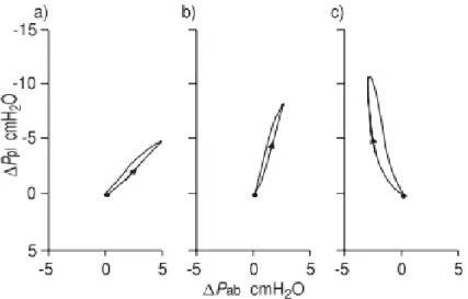
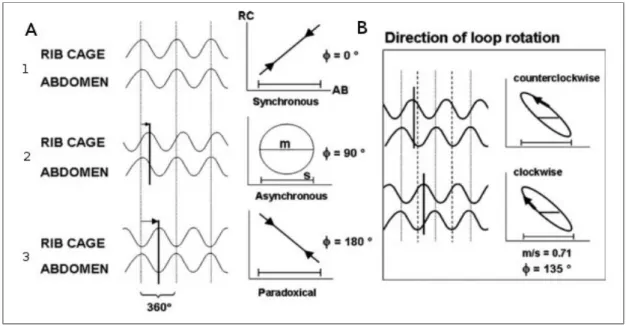
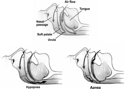
Figure 1.24 - Obstructed Bronchioles and air trapping mechanism _________________ 46 Figure 1.25 - Inspiratory pressure generation during tidal breathing ________________ 51 Figure 1.26 - Representation of RIP recording as time series and in the Lissajous figures in inspiration ______________________________________________________________ 52 Figure 1.27 - Phase Angles 1 and Loop rotation 2 of the Lissajous figures ___________ 53 Figure 1.28 - Partial and complete airway obstruction resulting in hypopnoea and apnoea.
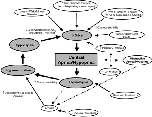
Figure 1.29 - Schematic of the many potential mechanisms contributing to
CSA/hypopnoea _________________________________________________________ 58 Figure 1.30 - Cheyne-Stokes breathing seen in a polysonnography recording _________ 59 Figure 1.31 -The principal factors that operate in controlling breathing during sleep (FRC: functional residual capacity)________________________________________________ 62 Figure 1.32 - Respiratory system model during: left) quiet breathing; right) fully ventilator control_________________________________________________________________ 64 Figure 1.33 - Mechanical Ventilator _________________________________________ 64 Figure 1.34 - Functional Scheme of a Mechanical Ventilator _____________________ 65 Figure 1.35 - Oronasal Mask ______________________________________________ 65 Figure 2.1 - General Architecture of a telemonitoring system _____________________ 70 Figure 2.2 - Architectural scheme of the whole system. __________________________ 76 Figure 2.3- DTS Acquisition _______________________________________________ 77 Figure 3.1 - Chronius Wearable System ______________________________________ 81 Figure 3.2 - Basic Architecture of wearable T-shirt integration on HMVMS __________ 82 Figure 3.3 - Schematic view of the complete system: HMVMS + Chronious Shirt ____ 82 Figure 3.4 - Global Structure of the DTS: _____________________________________ 84 Figure 3.5 - FOX BOARD LX832 __________________________________________ 85 Figure 3.6 - GPRSKIT ____________________________________________________ 86 Figure 3.7 - Schema of the Chronius Wearable system ___________________________ 89 Figure 3.8 - T-shirt with the Einthoven triangle and its lead _______________________ 90 Figure 3.9 - Nonin 8000R reflectance pulsioxymetry sensor ______________________ 91 Figure 3.10 - Inductive bands ______________________________________________ 91 Figure 3.11 - The respiratory inductive plethysmography_________________________ 92 Figure 3.12 - The controller unit ____________________________________________ 93 Figure 3.13 -.Photograph of the sensor system._________________________________ 94 Figure 3.14 - The Data Handler and its user interface ___________________________ 95 Figure 3.15 - General overview of the DH main processor interfaces. _______________ 96 Figure 3.16 - Li-Po battery LPP 503759 by Varta AG____________________________ 96
Figure 3.17 - Overview of the Data Handler Main Board __ 97
Figure 3.18 - The ECG device block diagram. _________________________________ 98 Figure 3.19 - RespiSENS block diagram._____________________________________ 98 Figure 3.20 - RespiSENS block diagram _____________________________________ 99 Figure 3.21 - sub-miniature D connector_____________________________________ 100 Figure 3.22 - Schematic view of the cable and its connectors_____________________ 100
Figure 3.23 - 4 pins connector of ECG electrodes and respiratory bands ____________ 101 Figure 3.24 - Nano Bluetooth USB 2.0 dongle by Mediacom ____________________ 101 Figure 3.25 - Word of bits in RS-232 Standard ________________________________ 103 Figure 3.26 - Two piconets forming a scatternet _______________________________ 104 Figure 3.27 - Bluetooth Protocol Stack ______________________________________ 105 Figure 3.28 - Pairing and authentication mechanism ___________________________ 108 Figure 3.29 - Client-server architecture______________________________________ 115 Figure 3.30 - TCP Header ________________________________________________ 116 Figure 3.31 - General Structure of ShirtSIG System ____________________________ 117 Figure 3.32 - BlueZ stack: modules and utils _________________________________ 119 Figure 3.33 - Sintetic view of ShirtSIGCoder main concept _____________________ 122 Figure 3.34 -1 ShirtSIGCoder flow chart Initialization procedures ________________ 127 Figure 3.34 - 2 - ShirtSIGCoder flow chart: __________________________________ 128 Figure 3.34 - 3 - ShirtSIGCoder flow chart ___________________________________ 129 Figure 3.35 - ShirtSIGViewer.vi front panel __________________________________ 131 Figure 3.36 - Connection Starter block______________________________________ 133 Figure 3.37 - Data Reading and Checking block ______________________________ 134 Figure 3.38 - Visualization and saving block _________________________________ 135 Figure 3.39 - TCP Connection Closer and Error Handler ________________________ 135 Figure 3.40 - Resumptive Overview of the ShirtSIG System _____________________ 136 Figure 4.1 - Schema of the experimental setup in running condition 1______________ 139 Figure 4.2 - Schema of the experimental setup in running condition 2______________ 139 Figure 4.3 - Schema of the experimental setup in running condition 3______________ 140 Figure 4.4 - S/Nex average values for each signal type in running condition 1 (RC1), running condition 2(RC2), running condition 3(RC2) ___________________________ 143 Figure 4.5 - Schema of the experimental setup in running condition 4 _____________ 144 Figure 4.6 - Schema of the experimental setup in running condition 5______________ 145 Figure 4.7 - S/Nex average values for each signal type in running condition 2 (RC2), running condition (RC4), running condition 3(RC2), running condition (RC5) _______ 146 Figure 4.8 -Schema of the experimental setup of the reliability test on long time
acquisitions ____________________________________________________________ 147 Figure 4.9 - Experimental setup of the pathological events recognition test__________ 149 Figure 4.10 - Simulation protocol structure___________________________________ 151 Figure 4.11 - Quite breathing tracks ________________________________________ 152 Figure 4.12 - OSAS simulation tracks _______________________________________ 153
Figure 4.13 - Central Apnoeas simulation tracks_______________________________ 154 Figure 4.14 - Chest-wall Asynchronies simulation tracks ________________________ 155
List of Tables
Table 3.1: Dataframe structure_____________________________________________ 109 Table 3.2: Dataframe Length bytes structure__________________________________ 110 Table 3.3: Timestamp bytes structure _______________________________________ 110 Table 3.4: Data Handler data ID ___________________________________________ 110 Table 3.5: ECG data Structure: MSB=most significant byte LSB=less significant byte 111 Table 3.6: RespiSENS data Structure _______________________________________ 112
Table 3.7: RespiSENS data range __________________________________________ 113
Table 3.8: PusiOximeter data structure ______________________________________ 113 Table 3.9: Temperature and Humidity sensors data structure _____________________ 114 Table 4.1: Average values of the S/R, T/S and S/Nex ratios in running conditions 1 (A) 2(B) 3(C) for each signal type. _____________________________________________ 142 Table 4.2: Average values of the S/R, T/S and S/Nex ratios in running conditions 4(D) and 5(E) for each signal type__________________________________________________ 146
Sommario
Le malattie croniche respiratorie sono tra le maggiori cause di morte in tutte le regioni del mondo, esse possono provocare una perdita irreversibile delle funzioni respiratorie a seguito di disfunzioni ventilatorie e di anomalie nello scambio di gassoso o di una combinazione di queste componenti.
La Broncopneumopatia Cronica Ostruttiva (BPCO) è un malattia cronica dei polmoni caratterizzata da un’infiammazione cronica e da una progressiva e irreversibile ostruzione delle vie aeree.
I pazienti affetti da COPD spesso soffrono di alterazioni notturne respiro che risultano nei Disturbi Respiratori del Sonno (DRS), caratterizzati da anomalie nel ritmo respiratorio, variazioni nella ventilazione e alterazioni nella struttura del sonno.
Lo scopo di questa tesi è stato di implementare e testare lo ShirtSIG System, un sistema di telemonitoraggio a tempo reale delle condizioni del paziente durante il trattamento con ventilazione meccanica non invasiva nel sonno.
ShirtSIG System è stato realizzato integrando il Chronious Wearable system – un maglietta ergonomica dotata di sensori intelligenti atti a monitorare continuamente i parametri fisiologici del paziente – con lo Home Mechanical Ventilation Monitoring System (HMVMS),un sistema sviluppato dal TBM Lab. Il sistema complessivo permette il monitoraggio costante di diversi parametri di ventilazione e permette al clinico di realizzare una titolazione remota del ventilatore.
Il sistema complessivo stato sviluppato e testato per valutare le sue performance.
I risultati dei test hanno mostrato che ShirtSIG System è in grado di immagazzinare i dati acquisiti in una memoria dedicata e di trasmetterli via Internet. Dato che i dati inviati vengono acquisiti dallo stesso dispositivo, è stato riscontrato che le sue capacità computazionali non sono sufficienti per gestire l’elevato flusso di dati, compromettendo l’affidabilità delle caratteristiche dell’intero sistema. Tuttavia, grazie ai dati trasmessi il clinico può facilmente riconoscere eventi e condizioni patologici specifici ai fini di realizzare una migliore titolazione domiciliare a distanza e di adattarla alle specifiche esigenze del singolo paziente.
Abstract
Chronic respiratory diseases (CRD) are a major cause of adult deaths in all regions of the world and they produce irreversible loss of pulmonary function due to ventilatory dysfunctions, gas exchange abnormalities, or a combination of both.
Chronic Obstructive Pulmonary Disease (COPD) is a chronic lung disease characterised by chronic inflammation and a progressive irreversible obstruction of airflows. COPD patients frequently suffer from nocturnal alterations in ventilation and gas exchange resulting in the Sleep Disordered Breathing (SDB), a group of disorders characterized by abnormalities of respiratory pattern or the quality of ventilation during sleep.
The aim of this work of thesis was focused on the implementation of the ShirtSIG System, a real time telemonitoring system used to monitor the patients' state during non-invasive mechanical ventilation during sleep.
The ShirtSIG System has been realized by the integration of the Chronious wearable system - an ergonomic designed shirt equipped with sensors which allow to monitor continuously patients’ physiological parameters - with the Home Mechanical Ventilation Monitoring System (HMVMS) developed by TBM Lab. The whole system allows the constant monitoring of different ventilation parameter and allows the physician to realize a remote titration of the ventilator. The whole system has been developed and tested to evaluate its performances.
The results of the test conducted have shown the ShirtSIG System able to store the acquired data on a dedicated memory and transmit them through the internet. As data coming from two different systems are acquired by the same device, it has been found that its computational capabilities are too low to manage the elevated flow of data, thus compromising the reliability and the real-time features of the whole system.
Nevertheless thanks to the transmitted data, the physician can easily recognize specific pathological events and conditions in order to perform a better titration at patient’s home at distance and tailor it on specific needs of each single patient.
Introduzione
La ventilazione meccanica (VM) è una terapia che viene somministrata per assistere o sostituire meccanicamente la ventilazione in soggetti affetti da malattie del sistema respiratorio nei quali è compromessa la capacità di fornire la necessaria ventilazione ai polmoni. La VM viene impiegata spesso su pazienti con patologie croniche respiratorie che richiedono assistenza ventilatoria domiciliare a lungo termine. E’ importante garantire un buon adattamento del paziente al ventilatore meccanico nell'ambiente domestico attraverso la titolazione corretta del ventilatore stesso. Attualmente tale procedura viene effettuata in ospedale durante una breve visita che spesso non include un test notturno. Nella prima settimana (dieci giorni) successiva alle dimissioni dall’ospedale, le impostazioni della ventilazione precedentemente fatte potrebbero non essere più quelle ottime per molte ragioni: perché lo stato clinico del paziente potrebbe variare, perché le attività giornaliere del paziente, e quindi il tipo di ventilazione, potrebbero essere differenti da quelle fatte durante la visita di prova e set up dei parametri del ventilatore.
Allo stato attuale dell'arte il personale medico verifica l’adattamento tra paziente e ventilatore tramite delle brevi visite ospedaliere ogni 4-6 mesi, con liste di attesa molto lunghe, e senza la garanzia di una titolazione del ventilatore ottima per il paziente al proprio domicilio. Esistono pochissimi sistemi in grado di permettere al medico un monitoraggio remoto della qualità della ventilazione e un sistema per la titolazione remota offline.
L’obiettivo di questo lavoro di tesi è quello di assemblare e testare un nuovo sistema che permetta al personale medico di poter effettuare il monitoraggio e la titolazione della ventilazione meccanica domiciliare a distanza, in particolare applicata a patologie croniche del sistema respiratorio, al fine di ottimizzare la terapia ventilatoria fornita.
Il primo capitolo fornisce una breve introduzione all’anatomia del sistema respiratorio e alle malattie che lo possono colpire, in relazione allo scopo di questo lavoro: la malattia cronica ostruttiva polmonare (COPD), disturbi sonno correlati (SDB) e la sindrome dell’apnea notturna (SAS).
telemonitoraggio remoto di pazienti cronici domiciliati, evidenziandone i limiti dovuti principalmente alla mancanza di interazione in tempo reale tra medico e ventilatore in funzione e alla impossibilità da parte del personale ospedaliero ad intervenire per modificare le impostazioni del ventilatore a seconda delle necessità del paziente.
Un aspetto importante descritto in questo capitolo è una panoramica su due sistemi implementati in progetti precedenti. Un dispositivo descritto permette la connessione remota in tempo reale tra paziente (ventilatore meccanico) e medico, il quale può visualizzare in tempo reale i parametri di respiro del paziente (pressione, flusso, perdite, volume corrente) dall’ospedale grazie ad una connessione ad internet e può intervenire cambiando i parametri di ventilazione del dispositivo domiciliare. Il secondo dispositivo introdotto è parte di un progetto europeo (Chronious) ed è composto da un sistema indossabile per il monitoraggio remoto offline di vari parametri fisiologici (movimenti di addome e torace, pulsossimetria, ECG, temperatura, umidità…). L’utilizzo dei due sistemi integrati permette il monitoraggio remoto in tempo reale della ventilazione meccanica somministrata attraverso un più completo set di parametri che aiuta il personale medico a titolare e monitorare la terapia ventilatoria somministrata in modo più accurato ed adatto alle condizioni del singolo paziente.
Il capitolo terzo è dedicato alla descrizione del dispositivo nella sua integrità, sia dal punto di vista hardware che software. Viene inoltre descritto il lavoro che è stato effettuato per unificare i due sistemi differenti in un articolato e più completo dispositivo in grado di campionare segnali provenienti sia dal ventilatore meccanico domiciliare che dal sistema indossabile, entrambi utilizzati durante il sonno dei pazienti.
Il primo sistema è composto da un dispositivo basato su un microprocessore su cui è installato linux embedded e che viene connesso tramite protocollo USB al ventilatore meccanico e ne campiona i segnali di pressione, flusso, perdite e volume corrente. Tali segnali vengono salvati in una memoria interna insieme ai parametri campionati dal sistema indossabile il quale tramite una connessione Bluetooth li comunica al sistema principale. Il sistema indossabile è composto da una maglietta fatta di materiale elastico in cui sono cucite due bande elastiche per la misura degli spostamenti toracici ed addominali, quattro elettrodi per l’elettrocardiografia, un pulsossimetro a riflettenza, un sensore ambientale per misurare temperatura ed umidità ed un accelerometro per determinare la posizione del paziente.
Il sistema principale si connette ad internet tramite un modem GPRS ed agisce da server attendendo la connessione da parte del computer remoto del personale medico, il quale, una volta autenticato, tramite apposito software è in grado di visualizzare le tracce di tutti i parametri in tempo reale e di modificare le impostazioni del ventilatore da remoto.
Il quarto capitolo descrive i test, effettuati su soggetti sani, a cui è stato sottoposto il sistema realizzato per verificarne funzionalità e affidabilità. Anzitutto è stata testata la capacità del sistema finale di acquisire i dati in tempo reale da entrambi i sistemi senza perdita di informazione o compromissione della caratteristica di tempo reale. Il sistema ha mostrato delle fragilità da questo punto di vista dovute in gran parte alla scarsità della capacità di calcolo del sistema centrale, non sufficiente per gestire il campionamento da due sistemi complessi.
I test successivi sono stati effettuati utilizzando una versione alleggerita del sistema in modo da poter verificare il funzionamento su lungo periodo, ovvero durante l’acquisizione notturna di 8 ore. Inoltre è stata testata e dimostrata l’affidabilità del sistema in termini di segnali visualizzati sul terminale del personale medico, sul quale è possibile riconoscere e discriminare gli eventi tipici delle patologie in esame, quali ad esempio apnea ostruttiva o centrale e respiro paradosso.
Il capitolo quinto riporta le conclusioni riguardo il sistema complessivo, evidenziando la necessità di potenziare la tecnologia utilizzata per mantenere la condizione di tempo reale senza perdita di informazione e evidenzia la necessità di verifica del sistema su pazienti COPD e SAS.
Il sistema ha dimostrato possibilità di adattamento e scalabilità e la sua utilità per la titolazione ed il monitoraggio remoto di pazienti respiratori cronici al loro domicilio.
Chapter 1 - Anatomy, physiology and
pathologies of the respiratory system
1.1 Introduction
Respiration is the motor of life; it is one of the seven characteristic processes shared by all living organisms together with movement, sensitivity, nutrition, growth, excretion ad reproduction.
Breathing in an essential function and must occur all the day time during the life, in the conscious or unconscious state, awake or asleep.
The main respiratory function is to attempt gas exchange with the environment, delivering oxygen to the body metabolism, and removing carbon dioxide and other residual substances consequentially produced, which are toxic for the cells and must be expelled from intracellular environment.
The respiratory and circulatory systems act together to achieve these functions.
With their action, respiration and circulation, contribute to correct conditions for metabolism, providing the requested amount of oxygen to the tissues and removing carbon dioxide from the body. (Figure 1.1).
Figure 1.1 - Schematic overview of the respiratory and circulatory systems action totransport oxygen from the outside air to the peripheral cells and to transport carbon dioxideback from the cells to the outside air.
The respiratory system not only achieve to gas exchange but provide a defence against bacterial, viral and other infectious agents, regulates temperature, and stabilizes blood acid-alkaline balance (pH), playing a fundamental role in the whole body homeostasis.
The impairment of one or most of this function leads to a pathological state that affects normal breathing. This can cause alterations in respiratory system structure and function, finally leading to a condition of respiratory disease.
Respiratory diseases can arise from a number of causes, including inhalation of toxic agents, accidents, and harmful lifestyles, such as smoking, infections and genetic factors, either directly or indirectly, and can affect one or more parts of the respiratory system. Some of them may temporary and relatively harmless; others may be life-threatening and persists during the all life time: these lasts it can be classified as chronic respiratory disease.
Chronic respiratory diseases (CRD) are the major cause of premature adult deaths in all regions of the world in the developed as well as in the developing countries [57].
Impairments caused by chronic diseases of the respiratory system generally produce irreversible loss of pulmonary function due to ventilation dysfunctions, gas exchange abnormalities, or a combination of both.
One of the most widespread and cost-effective [49] CRD is Chronic Obstructive Pulmonary Disease (COPD).
Chronic obstructive pulmonary disease (COPD) is a chronic lung disease characterised by a progressive obstruction of airflow that cannot be fully reversed. It is considered the fourth leading cause of death, affecting 14 millions adults in the United States [57], and the previsions sets it to be the third by 2030.
Active smoking remains the main risk factor, but other factors are becoming better known, such as occupational factors, infections and the role of air pollution [59].
COPD is often associated with significant comorbidities.
For example patients with COPD frequently suffer from nocturnal alterations in ventilation and gas exchange resulting in sleep disorders breathing.
Sleep-Disordered breathing (SDB) describes a group of disorders characterized by abnormalities of respiratory pattern or the quantity of ventilation during sleep [19]. The consequences of the abnormal breathing during sleep include excessive daytime sleepiness, hypertension, stroke risk, myocardial infarction, heart failure, metabolic
dysfunction and neurocognitive dysfunction [15, 16, 17]: sleep-disordered breathing indeed, adversely affects daytime alertness and cognition and is associated with
cardiovascular disease, particularly in men aged 40–70 years[25]. There can be recognized several types of breathing disorders during sleep; symptoms may include snoring, pauses in breathing, and disturbed sleep.
Most widespread of them are sleep apneoa-hypopneoa syndromes, that are central and obstructive apnoea syndromes.
Sleep-disordered breathing (mainly obstructive sleep apnoea OSA) and COPD are among the most common pulmonary diseases, so a great number of patients have both disorders; substantial number of patients will have both OSA and COPD.
This common combination of OSA and COPD has important implications for diagnosis, treatment, and outcome. Specifically, patients with COPD and OSA have a substantially greater risk of morbidity and mortality, compared to those with either COPD or OSA alone [75, 76, 77].
The goals of therapy for subjects affected by such combination is to improve lung mechanics as well as gas exchange ultimately leading to better sleep quality and health status: currently, treatment consists on the application of nocturnal non-invasive mechanical ventilation to the patients.
In the first part of this chapter, the general anatomy and physiology of the respiratory system will be analysed.
The second part, instead, offers a description of the of COPD and sleep apnoeas in order to better understand the pathophysiological mechanisms that can make nocturnal continuous monitoring a useful aid to titration during NIPPV treatments.
1.2 Anatomy of the human respiratory system
In mammals the respiratory system consists of the set of organs and tissues that contribute to capture oxygen from the environment and give out the carbon dioxide that is produced as a result of metabolism within the cells [1].
The main components of the human respiratory system are lungs where gas exchange between blood and air take place, the airways that connect the lungs to the outside environment, and the structures in the chest - rib cage and diaphragm - involved with the respiration movements that bring air in and out of the lungs. (Figure 1.2).
The airways are divided in the upper airways; include the nasal passage, the oral cavity the pharynx and larynx, and the lower airways comprise, the trachea, bronchi.
1.2.1 Upper Airways: nose, mouth, pharynx and larynx
Breathing starts at the nose and the mouth.
The upper airways, is in the fact, the primary conduit for passage of air into the lungs. Air enters the body through the nose, and is gradually warmed, humidified and partially filtered: these functions together realized the primary air condition by the upper respiratory airway.
The filtration function of upper airways [3] is made in two principal ways:
By the hairs and cilia at the entrance to the nostrils, important for filtering out large particles.
By turbulent precipitation; the air passing through the nasal passageways hits many obstructing vanes and the particles suspended in, having far more mass and momentum than air, cannot change their direction of rapidly as the air can. Therefore, they stop and remain entrapped in the mucous coating.
The filtration function is reduced in mouth breathing. For example, if nasal respiration removes SO2 25 ppm concentrated, this capacity is reduced of 65% in oral ventilation [6]. After the nose and the mouth, the airflow continues into nasal passages through pharynx, a fibrous-muscular channel, common to both the respiratory and the digestive system, where filtering and warming processes go on. The larynx is a tube-shaped organ in the neck that contains the vocal cords. The larynx is about 5 cm long. It is part of the respiratory system and is located between the pharynx and the trachea [5].
Ordinarily, thetemperature of the inspired air rises to within 1°F of body temperature and to within2 to3per centof fullsaturationwith watervapour before it reaches thetrachea[3].
Figure 1.3 - Upper Airways
and active to neural influences contribute to its patency and collapsibility.
This total structure forms a passage for movement of air from the nose to the lungs and also participates in other physiological functions such as phonation and deglutition. The properties of the upper airways are a compromise between these different functions, which variably require maintenance of patency, during breathing, or closure of the airway, as in swallowing [7].
Modification of the structural properties of the upper airway may lead to respiratory dysfunction that can affect the whole respiratory system.
1.2.2 Lower Airway: trachea, bronchi, alveoli
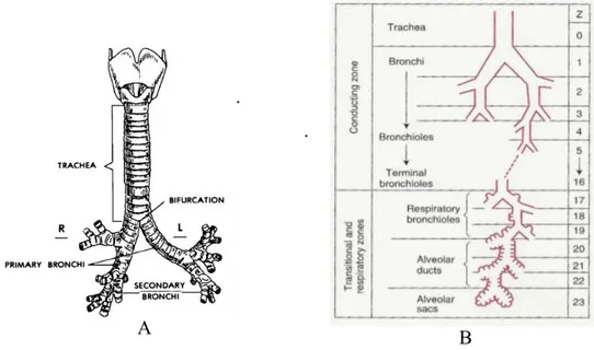
The lower respiratory tract, or lower airways, extends from the larynx to the most distal portions of the lung parenchyma airways and consists of a series of branching tubes which become narrower, shorter, and more numerous as they penetrate deeper in to the lung [5]. Starting from the trachea, which divides in to right and left main bronchi the process, continues down to the terminal bronchioles: it can be distinguished 23 generations of bronchi in the trachebronchial tree (Figure 1.4).
.
.
Figure 1.4 – LowerAirways:
A.Tracheobronchial Tree B.Division of lower airway in smaller-diameter ducts
Proceeding down toward the lungs, the diameter of the single duct became smaller, but the number of ducts increases. Total section gradually reduces and the consequential
fluidodynamics makes the air flow speed decreased near to zero into the alveoli.
Functionally lower airways can be considered in two groups: conducting and transitional. The former comprises those whose walls do not contain alveoli and are thick enough to prevent gas diffusing into the adjacent lung parenchyma. They include the first sixteen generations of bronchi, the trachea, bronchi, and membranous non-alveolated bronchioles. Their main functions are humidification, purification and gas transportation.
Because the conducting airways contain no alveoli and therefore take no part in gas exchange, they constitute the anatomic dead space: its volume is about 150 ml [5].
The transitional airways, instead are starting from the seventeenth generation of bronchi: these are named respiratory bronchioles [6], structurally defined by the absence of cartilage in their walls because the function of transportation is gradually replaced by the function of diffusion.
These airways, along with their accompanying arteries and veins, lymphatic vessels, nerves, interlobular septa, and pleura, constitute the non-parenchymal portion of the lung. As the name suggests, transitional airways have both conductive and respiratory functions: in addition to conducting gas to and from the most peripheral portion of the lung, each has alveoli on its wall that serve in gas exchange.
Alveoli associated with the transitional airways and with the more distal alveolar sacs constitute the lung parenchyma. It has been estimated that approximately 87% of the total lung volume is alveolar, 6% of which is composed of tissue, and the remainder of which is gas. [1].
There are almost 130.000 respiratory bronchioles connected to the same number of acini -that is a cluster of ducts and alveolar sacs – each of them, about 3.5 mm large.
Respiratory bronchioles divide into alveolar ducts (generation 20-22), and alveolar sacs on which walls develops almost the 50 percent of the alveoli (Figure 1.5).
1.2.3 The lungs
All the structure previously described concurred in the composition of the lungs.
The lungs are a pair of spongy, air filled organs located on either side of the chest: their primary function is the gas exchange between air and blood. (Figure 1.6).
Figure 1.6 - The lungs
The lungs are protected by the ribcage and are covered, as the inside of the whole chest cavity, by a two-layer elastic tissue layer called the pleura.
A thin layer of fluid in the pleural cavity acts as a lubricant allowing the lungs to slip smoothly as they expand and contract with each breath.
The space between both lungs is occupied by the heart, the two main bronchi that transport gas to and from both lungs, and the oesophagus which leads to the stomach [4].
The diaphragm stays at the bottom of the lungs there and is a thin dome-shaped skeletal muscle that extends across the bottom of the rib cage.
The diaphragm plays an important role in breathing: it contracts with each inspiration, enlarging the volume of the thoracic cavity This reduces intra-thoracic pressure, which creates a depression that draws air into the lung. [6].
The right lung is larger in volume and shorter than the left lung. The left lung must leave room for the heart. The right lung is divided into three pulmonary lobes (upper, middle and lower) and 10 bronchopulmonary segments .
The left lung is smaller and narrower than the right lung and is divided into two pulmonary lobes (upper and lower) and eight bronchopulmonary segments.
A pulmonary lobe is a major subdivision of a lung marked by fissures: each lobe is further partitioned into bronchopulmonary segments, composed by many small compartments called lobules (Fig.1.7)
Figure 1.7 - Lung lobule
There are about 300 million alveoli in the human lung, each about 0, 3 mm in diameter. Their total surface would be 85 square meters, but their volume only 4 litres. By contrast, a single sphere of this volume would have an internal surface area of only 1/100 square meter.
1.3 Physiology of respiration
1.3.1 The act of breathing
In order to breathe, we must continuously contract and relax our respiratory muscles about 30,000 times a day, and billion times for a lifetime [1].
The respiratory muscles (Fig 1.8) move the parts of the chest wall that form the boundaries of the thoracic cavity, either enlarging or contracting their volume and thereby ventilating the lungs.
They act as a ventilatory pump.
This ventilatory pump is obviously essential for life and its action is to replenish the alveoli with fresh air (inspiration) and to expel alveolar gas from the lung (expiration).
Figure 1.8 - Muscles of Breathing. All the muscles that elevate the chest cage are classified as 'muscles of inspiration', those muscles that depress the chest cage are classified as 'muscles of expiration'
.
The lungs can be expanded and contracted in two ways:
by downward and upward movement of the diaphragm to lengthen or shorten the chest cavity,
by elevation and depression of the ribs to increase and decrease the anteroposterior diameter of the chest cavity.
In normal quiet breathing the first method almost entirely persists, by the movement of the diaphragm.
During inspiration, contraction of the diaphragm pulls the lower surfaces of the lungs downward. Then, during expiration, the diaphragm simply relaxes, and the elastic recoil of the lungs, chest wall, and abdominal structures compresses the lungs and expels the air. In heavy or active breathing, instead the second method occurs because lungs need to expand more, and the action of diaphragm and the elastic forces are not powerful enough to cause the necessary rapid expiration, so that extra force is achieved mainly by contraction of the abdominal muscles, which pushes the abdominal contents upward against the bottom of the diaphragm, thereby compressing the lungs.
Figure 1.9 - Dynamics of breathing
During inspiration the rise of the ribcage is realized by the external and parasternal intercostals muscles,and this in association with the contraction of the diaphragm allows thelungstoexpandmoreinthechestwall.
the anterior serrati, and the scaleni – acts lifting upward on the sternum and elevating the first ribs.
The lung compression isrealizedbythecontractionoftheinternalintercostalmuscles,that lower theribs; and by the abdominal muscles which pushes the abdomen upward against thebottomofthediaphragm,therebycompressingthelungs.
1.3.2 Air diffusion
Oxygenandcarbondioxidemovebetweenairandbloodbysimplediffusion.
Intheprocessofdiffusion,gasflowsbetweenairandbloodoccurspassivelydrivenbytheir partial pressure gradients.
The partial pressure of each gas in the alveolar respiratory gas mixture tends to force moleculesofthatgasintosolutioninthebloodofthealveolarcapillariesandviceversa.
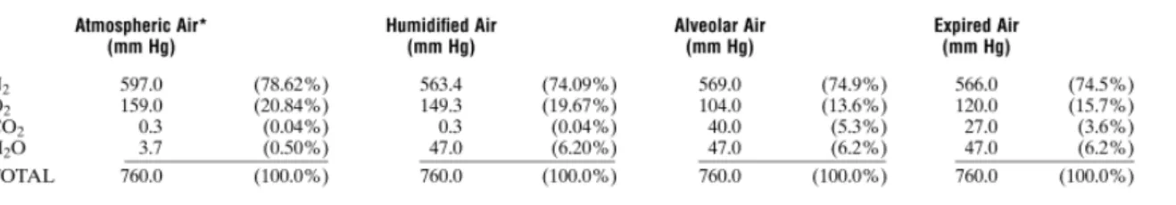
At alveolar level partial pressure of respiratory gases are not the same of the ones in atmospheric air: an overview of partial pressures of respiratory gases during respiration cycleisdescribedinFig.1.10.
Figure 1.10 - Partial Pressures of Respiratory gases as they enter and leave the lungs
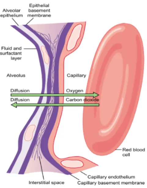
The gas exchange occurs at the contact zone between the alveolus and the pulmonary capillary: gas molecules dissolve into tissues passing through alveolar and blood vessels membranesandepithelium.
Figure 1.11 - Gas diffusion from alveoli to blood
Figure 1.12 - Partial pressures values from alveoli to tissues
to tissues. Giving attention to the oxygen diffusion process, it can be seen that the Po2 alveolus averages 104 mm Hg, whereas the Po2 of the gaseous oxygen in the of the venous blood entering the pulmonary capillary at its arterial end averages only 40 mm Hg because a large amount of oxygen was removed from this blood as it passed through the peripheral tissues.
Therefore, the initial pressure difference that causes oxygen to diffuse into the pulmonary capillary is 104 – 40, or 64 mm Hg.
When the arterial blood reaches the peripheral tissues, its Po2 rounds the tissue cells averages only 40 mm Hg. Thus, the pressure difference causes again oxygen to diffuse rapidly from the capillary to cells.
The mechanisms of diffusion of CO2 are driven by gradient of pressure, such the one of the
oxygen; but ruled by a different diffusion coefficient.
The diffusion coefficient is proportional to solubility of the gas and inversely proportional to the square root of the molecular weight. This means that CO2, diffuses about 20 times more rapidly than does O2 through tissue sheets because it has a much higher solubility but not a very different molecular weight.
Because of low solubility the oxygen dissolved in blood is almost about low concentrated – only 10-4 [6], and the oxygen flow that arterial blood provides represents only 5% of total amount necessary for metabolic consumption[6].
To have the right amount needed for metabolism, oxygen indeed, is carried through blood in two different ways: by the dissolution in plasma and by the binding with hemoglobin contained in red blood cells.
Hemoglobin is metalloprotein, able to bind molecules of O2 within alveolar capillaries and to carry them to tissues: it can also transport carbon dioxide from peripheral organs from tissues to lungs [6].
Figure 1.13 - Hemoglobine dissociation curve: At 100% of saturation, 1 g of
hemoglobin bind 1,34-1,39 ml of oxygen: if in the blood there were 15 g of hemoglobin for 100 ml of blood, in arterial blood there can be carried 20ml of O2 on 100 ml of blood [6]
Oxygen partialpressureregulates hemoglobin saturation,whichis the amount of oxygen,
can be bound to hemoglobinataspecificconcentration.
WhenPo2ishigh,asinthepulmonarycapillaries,oxygenbindswiththehemoglobin,but whenPo2is low,asinthetissuecapillaries,oxygenisreleasedfromthehemoglobin:this allowstheoxygendiffusionincells.
Thus, the uptake of oxygen can be summarized in the following stages: oxygen diffuses from alveoli through blood because of the difference in partial pressures, and depending on this oxygen binds with hemoglobine since the equilibrium between the oxygen dissolved and oxygen bound is reached.
The hemoglobin dissociation curve can be described by the Hill equation [10].
Assuming that the molecules of Hb might aggregate differently because of the various salts present in solution, and thus different aggregates of Hb might co-exist in the same solution, several simultaneous equilibrium reactions between oxygen and Hb might coexist as well. If a solution would contain only Hb and Hbn (an aggregate of n molecules of Hb), the
equilibrium reaction would be:
Hb+O2—>HbO2 [1.2]
In the special case of a solution with only Hb and Hb2, the equation of the dissociation curve of Hb proposed by Hill is:
+K x
x K λ + x K + λK = y2 1 2 1 100 1 1 2 2 [1.3]where y2 is the percent saturation of Hb, x is the partial pressure of O2 (mmHg), is the
percentage of Hb2, and (100 -) is the percentage of Hb. K1 and K2 were called by Hill the ‘equilibrium constants’ of the equilibrium reactions [10].
As can be seen on (1.3) the Hill equation mathematically shows the dependence of saturation on oxygen partial pressure: typically there are other several factors related to blood composition that influences hemoglobin oxygen-binding capacity, such increased carbon dioxide partial pressure and consequential changes in blood pH (acidosis and Bohr effect)[6], temperature and increased 2,3-biphosphoglycerate (BPG), a metabolically important phosphate compound present in the blood in different concentrations under different metabolic conditions[5].
This dependence graphically reflects in a shift of the dissociation curve (Figure 1.12). According to the Hill equation, the measurement of partial pressure of oxygen dissolved on blood can be considered an indirect estimation of the percent saturation of hemoglobin and at last can be a useful indicator of to gas exchange between the alveoli and blood, and of oxygenation of the tissues in pathological and physiological conditions.
1.3.3 Mechanics of respiration
The study of mechanics of respiration is a useful approach to have information on the physiological state of the respiratory system in normal and pathological conditions.
Essentially, this means to describe the statics and the dynamics of the whole and of each component of the apparatus.
Because the respiratory system and its parts have tridimentional geometry, get information about the dynamical and the statical variables, such as positions, displacements and forces means to measure volumes and pressures variation.
1.3.1.1 Lung volumes
Indescribingtheeventsofpulmonaryventilation,thevolumeofair engaged in the respiration act is conventionally subdivided into four volumes andfour capacities [4]. Thelastareacombinationoftwoormoreofthefirst and botharedefinedasfollow:
Figure 1.14 - Lung Volumes
the tidal volume isthevolumeofairinspiredorexpiredwitheachnormalbreath. the inspiratory reserve volume istheextravolumeofairthatcanbeinspiredover
andabovethenormaltidalvolumewhenthepersoninspireswithfullforce the expiratory reserve volume isthemaximumextravolumeofairthatcanbe
expiredbyforcefulexpirationaftertheendofanormaltidalexpiration the residual volume isthevolumeofairremaininginthelungsafterthemost
forcefulexpiration
the inspiratory capacity equalsthetidalvolumeplustheinspiratoryreserve volume.Thisistheamountofairapersoncanbreathein,beginningatthenormal expiratorylevelanddistendingthelungstothemaximumamount.
the functional residual capacity equals theexpiratoryreservevolumeplusthe residualvolume.Thisistheamountofairthatremainsinthelungsattheendof normalexpiration.
theexpiratoryreservevolume.Thisisthemaximumamountofairapersoncan expelfromthelungsafterfirstfillingthelungstotheirmaximumextentandthen expiringtothemaximumextent.
the total lung capacity isthemaximumvolumetowhichthelungscanbeexpanded with the greatest possible effort; it is equal to the vital capacity plus the residual volume
It's important to notice that the measures of pulmonar volumes are of two types:
absolutes: such as total lung capacity (TLC), functional residual(FRC) and residual volume (RV)
relatives: such as tidal volume. vital capacity, the inspiratory and expiratory reserve volumes and the inspiratory capacity
Relative measures of pulmonary volumes can be easily obtained by the integration of measures of the respiratory flow, conversely to the absolute ones that need more complex measurement protocol to be got.
Another way to obtain information about respiratory volumes is through pletismography, or rather the measure of the volume variation of the chest wall [10].
Pletismography can be realized in different modalities: the one used in this work is described in Chapter 3.
1.3.1.2 Pressures
It has been previously shown how respiratory muscles act as a respiratory pump.
The measures of pressure considered to describe the behaviour of such a pump, and thus of the mechanics of the respiratory system are typically the following ones:
Pbs (body surface) is the external pressure of the chest wall, in normal conditions it is worth the same value of the atmospheric pressure.
Ppl (pleural) is the pleural fluid pressure, in normal conditions it is worth less than the atmospheric pressure. It is not directly measured, perforating the membrane, but it is estimated from oesophageal pressure, introducing a catheter with a balloon in the oesophagus, which position is nearby the pleura.
Palv (alveolar) is the pressure into the alveoli.
Pao (airway opening) is the pressure at the entrance of airways (mouth), and it is the same of Palv if there are no pressure drops along the ducts.
Pl (lung) is the pressure at which the lung is subjected and it is called distension pressure (elastic pressure). Mathematically, it is the difference between alveolar and pleural pressures: Pl=Palv-Ppl. If Pl increases, the lung expands.
Pw (wall) is the pressure at which the chest wall is subjected t, and it is worth the difference between pleural and extern pressures: Pw=Ppl-Pbs.
Prs (respiratory system) is the pressure at which is subjected the respiratory system, and it is worth the sum between pulmonary and wall pressures, hence the difference between alveolar and extern pressures: Prs=Pl+Pw=(Palv-Ppl)+(Ppl-Pbs)=Palv-Pbs (in static conditions)
Figure 1.15 - Pressures within the respiratory system
1.3.1.3 Pressure-Volume curve in static conditions
Information on the mechanical behaviour of the respiratory system during breathing in healthanddisease can begainedanalysingthepressurevolumecurveinstaticcondition. The static pressure-volume (P-V) curve (Figure 1.16) of the respiratory system describes themechanicalbehaviourofthelungsandchest in conditions of constant air flow [12]. Such condition, during quite breathing, exists only at the end of an inspiration or expiration, when the air flow stops.
Figure 1.16 Pressure-volume curve in static condition: on the abscissa there is respiratory system pressure Prs in cmH2O, on the ordinate there is lung
volume expressed as percentageof vital capacity (residual volume is considered the zero).
The shape of the curve in an upright, awake, and relaxed subject is sigmoidal, with upward concavity at low inflation pressure and downward concavity at higher inflation pressure: that sigmoidal shape reflects the balance between the expansive force of the chest wall (diaphragm and rib cage) and the inward retractile force of the elastic recoil of lung parenchyma [12].
The slope of the curve represents the compliance of the respiratory system and its expression is:
dP
dV
=
C
/
[1.4] The compliance of a system expresses how easily it distends: high compliance is related at high distensibility and this occurs when the system is rather stretchable.At the lower end of the curve (low lung volume), the compliance is low, which means that there is a small change in volume for a large change in pressure: this region is below critical opening pressure, the threshold to prevent terminal airways and alveoli collapse, thus in that case extra-pressure is required to open them [15].
At the center of the curve the compliance increases resulting in a large change in volume for a small change in pressure.
At the upper end of the curve (high lung volume), the compliance decreases again and the lungs gets stiffer: at high expanding pressures, in fact, the lung is over inflated and oppose to further volume increases.
Out of normal conditions, low compliance indicates a stiff lung and means extra work is required to bring in a normal volume of air: this occurs as the lungs in this case become fibrotic, lose their distensibility and become stiffer.
In a highly compliant lung, indeed, as in emphysema, the elastic tissue has been damaged. Patients with emphysema have very high lung compliance due to the poor elastic recoil; they have no problem inflating the lungs but have extreme difficulty exhaling air. In this condition extra work is required to get air out of the lungs.
Figure 1.17 - The relaxation static pressure-volume curve of the lung, chest wall, and respiratory system in setting posture.The curve for the respiratory system is the sum of the individual curves.The horizontal distance from the curve to the zeropressure axes indicates the pressure exerted by the passive structure of the system at a givenvolume.
The volume curve of the respiratory system (RS) is given by the sum of the pressure-volume graphs of the lungs (L) and of the chest wall (CW).
PL = Pl = Palv – Ppl [1.5]
PW = Pw = Ppl – Pbs [1.6]
Prs = Pl + Pw = Palv – Pbs [1.7]
The chest wall contributes most to the curvature below FRC, and the lung contributes most to the curvature above FRC (Figure 1.17).
The lung curve is determined by the characteristic of the parenchyma, the curve of the chest wall derives from the passive behaviour of the tissue that constructs the chest and all organs which somehow interferes with lung movements, while the respiratory system curve is, at every volume, the combination of this two components.
At resting volume, volume corresponding at zero pressure of the respiratory system (FRC) the chest wall recoils outward (its transmural pressure at this volume is subatmospheric) with a pressure equal to that by which the lung recoils inward (its transmural pressure at this volume is greater than atmospheric pressure).
At zero pressure the lung is at its minimal volume, which is below RV.
Considering the chest wall alone, indeed, the pressure is negative at low volumes and FRC becomes positive when the volume is increased at approximately 60% of the VC: below this volume the chest wall tends to recoil outward.
At TLC, both the lung and chest wall pressures are positive, and they both require positive transmural distending pressures. During inspiration at volumes greater than 60% of VC, both systems tend to recoil inward, therefore muscular work is necessary to oppose to this tendency and to expand the thorax.
During expiration, the system (chest wall + lung) returns the elastic energy, stored during inspiration, coming back to its resting value.
Thus, the lung and the chest wall behave like two opposing springs in series.
Considering that also the ribcage is an elastic structure as the lung, the elastic energy released by the collapsing tendency of the lungs is balanced by the expanding tendency of the chest wall.
Thus is can be considered the total system compliance as: CW L RS C + C = C 1 1 1 [1.8] in which CRS is the compliance of the total respiratory system, CL is the compliance of the lung, and CCW is the compliance of the chest wall.
The role of surfactant
Two components contribute to lung elastic recoil. The first is tissue elasticity (1/3 of the totalelasticforces);thesecondisrelatedtotheforcesneededtochangetheshapeofthe air-liquidinterfaceofthealveolus(2/3ofthetotalelasticforces).
Expandingthelungsrequiresovercominglocalsurfaceforcesthataredirectlyproportionate tothelocalsurfacetensionoftheliquidfilmcoveringthealveoli.
ThelawofLaplacequantifiesthisforce:
R =
P 2T / [1.9]
Thepressureneededtokeepopenthealveoliisdirectlyproportionatetothesurfacetension attheinterfaceandinversely proportionatetotheradiusofthealveoli(Figure1.18).
Figure 1.18 - Laplace law applied to a spherical alveolus covered by a liquid film
The liquid film that covers the alveoli is called, surfactant and is a mixture of
phospholipids and proteins [6]. These hydrophobic molecules displace water molecules from the air-liquid interface, thereby reducing surface tension.
This reduction has three physiologic implications: First, it reduces the elastic recoil pressure of the lungs, thereby reducing the pressure needed to inflate them. This results in reduced work of breathing. Second, it allows surface forces to vary with alveolar surface area, thereby promoting alveolar stability and protecting against collapsing. Third, it limits the reduction of hydrostatic pressure in the pericapillary interstitium caused by surface tension [6].
Pathologic states may result from changes in lung elastic recoil related to an increase in compliance, as in emphysema, a decrease in compliance, as pulmonary fibrosis, or a disruption of surfactant with an increase in surface forces [5].
Hysteresis of the lung
AnimportantphenomenonthatisreadilyseeninP-Vcurvesis hysteresis.
Hysteresisreferstounrecoverableenergy,ordelayedrecoveryofenergy,thatisappliedtoa system.
Figure 1.19 - V-P curve during inflation (inf) and deflation(def)
The V–P curve during lung deflation is not the same as during lung inflation, reflecting statichysteresis(Figure1.19).
That is, the lung does not act as a perfect elastic system, in which any energy put in is immediatelyreturned.
This may involve three main mechanisms: plastic behaviour of tissue elements and true tissue hysteresis; surface hysteresis; and differences in the sequence of recruitment and derecruitmentoflungunitsbetweeninflationanddeflation [1].
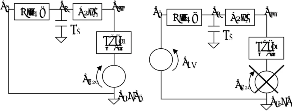
1.3.1.4 The electrical model of the respiratory system
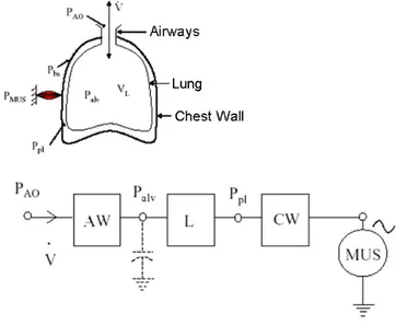
The mechanics of the respiratory system can be described using an analogous electrical modelconstitutedbytheseriesofairways(AW),lungs(L)andchestwall(CW).
The term corresponding to the current is the flow, while the voltage is the electrical analogousofthepressure.
TheairwayscauseapressuredropofPao-Palv,thelungscauseapressuredropofPalv-Ppl andthechestwallcauseapressuredropofPpl-Pbs.
Inthealveolithereareaircompressionandexpansionphenomena,whichareconsideredin themodelwithacapacitance.
The ventilatory pumpactedbyrespiratorymusclescanbemodelledas avoltagegenerator (MUS)representingthepressuregeneratedbythemuscles;thegeneratoractsonthepleural
pressurethroughthechestwall:whenitdecreasesthepressurethereistheinspiration,when itincreasesthepressuretheexpirationhappens.
Figure 1.20 - Airways model with muscles as active generator.
1.3.4 Nervous control of respiration
Breathingisunderthecontrolofthenervoussystemthatnormallyadjustsrhythmic ventilatorypatterninordertohandlethedemandsofthebodyofoxygen.
Cyclerhythmofbreathing is mainlygeneratedbygroupsof neurons locatedbilaterallyin themedullaoblongataandponsofthebrainstem (Figure 1.21) [3].
Figure 1.21 - Central Controller of respiratory system: they are the dorsal
respiratory group (DRG), which mainly causes inspiration a ventral respiratory group, the ventral respiratory group (VRG), involved both in inspiration and expiration and the pneumotaxic center or pontine neurons,which mainly controls rate and depth of breathing
The basic cycle of respiration is highly modified by several control mechanism and by voluntaryefforts:theirinteractionprovidesalargecapacityand flexibilitytotherespiratory system at the more diverse conditions.
Basically, respiration control is carried out with the regulation of the frequency and tidal volume during breathing in order to maintain the partial pressure of arterial oxygen and carbon dioxide within a narrow range, despite fluctuations in oxygen consumption, carbon dioxide production, and changes in metabolic demand [13].
Normal respiration maintains blood gas and acid-base homoeostasis within strict levels with minimal expenditure of mechanical energy.
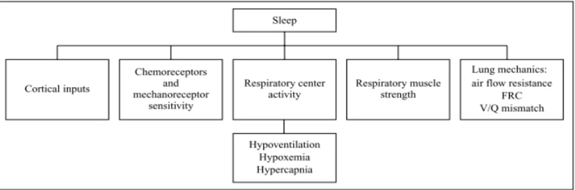
This homeostatic control system relies on three components:
1. Sensors, which gather information and feed it to the central nervous system, they are
o peripheral chemoreceptors, located in the carotid and aortic bodies, peripheral chemoreceptors are responsive to changes in PaO2, PaCO2 and pH. Those receptors are strongly linked to the cardiovascular function. Respiratorycessationandcirculatoryshockincreasechemoreceptoractivity, enhancing sympatheticoutflow to the heart and vasculature via activation of the vasomotor center[14].
o central chemoreceptors on theventral surface ofthe medulla oblongata, in directcontactwithcerebrospinal fluid,senses changesinhydrogenionand carbondioxideconcentrations.
o stretch receptors of the lungs and chest-wall and muscle
mechanoreceptors, the firsts monitor the lung stretching, to prevent overinflation:whenthisoccurs they signal the respiratory centers to exhale and inhibit inspiration. The seconds respond to changes in length, tension or movementoftherespiratorymuscles.
o irritants receptors: locate in the airways they sense the presence of toxic substances in the airways, their signals the respiratory causes the contractionof
the respiratory muscles, causing coughing and sneezing.
2. Central controller consists of the neuron of the brainstem group, that realize involuntary control and the cerebral cortex structures that are involved in voluntary control.
Figure 1.22- Schematic representation of the Nervous Respiratory control system
Thisstructurerealizeda negative feedback control system.
This feedback can be modulated by higher cortical centres, realizing the voluntary control effort.
Abnormalconditions stimulate thesystemaction that modifiestheventilationpatternin
1.4 Respiratory disorders
1.4.1 Chronic obstructive pulmonary disease (COPD)
Chronic obstructive pulmonary disease (COPD) is adiseasestatecharacterizedby poorly reversible airflow limitation that is not is usually progressive and associated with an abnormal inflammatory response of the lungs [41]. COPD is currently the fourth leading cause of death in the world, and further increases in the prevalence and mortality of the diseasecanbepredictedinthecomingdecades[44, 57,and 58]. The prevalence ofCOPD in the general population is estimated to be, 1% across all ages rising steeply to 10% amongst those aged 40 years the prevalence climbs appreciably higher with age [58] and betweensmokers [49]. The chronicairflow limitationcharacteristicofCOPDiscaused by the structural changes occurring with inflammation of the central and peripheral airways, lung parenchyma, and pulmonary vessels: these include inflammation of the peripheral airways, which characterizes obstructive bronchiolitis; parenchymal destruction, which characterises emphysema; and inflammation of the central airways, which characterizes
chronic bronchitis [41].
Figure 1.23 - Anatomopathological representation of Chronic bronchitis, Obstructive bronchitis and Emphysema