Titolo
Preliminary analysis of an aircraft impact
Ente emittente CIRTEN
PAGINA DI GUARDIA
DescrittoriTipologia del documento: Rapporto tecnico/ Technical Report
Collocazione contrattuale: Accordo di programma ENEA-MSE: tema di ricerca "Nuovo nucleare da fissione"
Argomenti trattati: Reattori ad acqua leggeralLight Water Reactors
Sommario
That report has been issued in the frame of the second research programme of ENEA-MSE agreement and it is one of the deliverables of the task L "External events analysìs" of the work programme 2 "Evolutìonary INTD reactors" of the research theme on "Nuovo Nucleare da Fissione".
The report deals wìth the results of the preliminary analyses aimed at evaluating the globai and Iocai structurai effects on
military aircrafts. Note Copia n. 2 1
o
the IRIS containment due to a horizontal crash of commerciaI and
In carico a: NOME FIRMA NOME FIRMA
CONSORZIO INTERUNIVERSITARIO PER LA RICERCA TECNOLOGICA NUCLEARE
UNIVERSITA’ DI PISA
DIPARTIMENTO DI INGEGNERIA MECCANICA NUCLEARE E DELLA PRODUZIONE
Preliminary analysis of an aircraft impact
AUTHORS
Prof. G. FORASASSI Dr. R. LO FRANO
CIRTEN-UNIPI RL 1059/2010
CONTENT
1. Introduction ……….……….… 2
2. Aircraft Impact Modelling ………. 6
3. Global Response Evaluation ……….……….... 10
4. Numerical Analysis ……….………..……….…… 15
5. Numerical Results ……….……….……… 20
6. Conclusion ……….………. 27
1. Introduction
Nuclear power plants have always been designed and constructed in order to maintain a suitable level of safety even in condition pertaining to severe internal as well as external accidents as: large fires, floods, earthquakes, hurricanes and also possible devastating events, both natural or produced by vicious activities, that might occur and influence the plant safety and security all of which must be factored into the basic reference accident design conditions.
Accordingly NPPs must be constructed and operated in order to protect individuals, society and the environment against an uncontrolled release of radioactivity also in the case of a jet aircraft crash this accident has become very significant after the tragic September 11, 2001 event in NY City.
NPP design must include multiple redundant systems to ensure essential nuclear safety functions, such as reactor core cooling, and integrity of the containment structure, in all the considered conditions. These functions should be maintained particularly in the event of the mentioned large aircraft impact.
Based on the premise that such an aircraft crash would be accidental, in the past, the requirement for aircraft impact evaluation was not given much attention in the licensing by the U.S. Nuclear Regulatory Commission, even if this event was considered in NPP licensing process in other countries and in the IAEA recommendations[1], because of the probability of an accident of this type was relatively low (evaluation through probabilistic assessment methods) particularly even for the few nuclear power plant sites located not so far from airports.
The requirements for the aircraft crash were introduced for nuclear reactors in 1979/80 in the UK and France respectively and for chemical separation and nuclear fuel plants such as those at Sellafield and Cogema in 198/92 in the UK and France.
In assessing accidental aircraft crash probability the guidelines and principles set out by the US Department of Energy, are generally adopted [1]. Essentially, this approach assumes some form of loss of control of the subject aircraft, its subsequent deviation from the intended flight path and the chance of it crashing into the target nuclear plant.
The nuclear plant is defined as a crash area and the parameters relating to this are calculated from the effective fly-in, footprint, shadow and skid areas that are determined from established codes. Due to the fact that this probabilistic approach yields a very low accidental crash probability (<107 per year), the risk connected to the occurrence of this type of accidental event,
After the Sept. 11, 2001, terrorist attacks on the United States (Figs.1) that raised public concern for the potential of a large aircraft crash into critical structures, including power plants, NPP safety against an accidental aircraft impact itself is become again widely discussed and investigated.
In this framework it is important to stress that “there is no experience of damage induced by
aircraft falling on nuclear islands, although some crashes have been recorded in their vicinity, sometimes with long skidding (300 m) of the engines far from the impact areas, with damage to residential and industrial facilities” [2-3].
Fig. 1 - Sept. 11, 2001, terrorist attacks consequences
Most of the researches available on high speed aircraft impacts into rigid and/or deformable bodies as well as on the response of the impacted nuclear containment structure are limited and antecedent the mentioned attacks on the World Trade Center in 2001 [4-5-6]; whilst as it is already mentioned, other evaluation analyses addressed non-malevolent aircraft impact using probabilistic approaches [7].
It is interesting to note that the design of old NPP containment design, being pre September 11 2001, was not specifically designed to resist any impact loading greater than a light aircraft crash which was the accepted design basis case drawn from the improbability or pure chance of a civil airliner accidentally crashing onto a nuclear power plant.
Nuclear power plants are already recognised to have a robust structures, therefore the impact of a military or civilian aircraft would not be expected to penetrate the containment of a reactor building, which at present would be a double containment made of heavily steel bar reinforced concrete with thickness of more than one metre at least, such as Areva's EPR and the Russian VVER-1200 containment walls, designed to withstand large earthquakes, extreme overpressures and hurricane force winds.
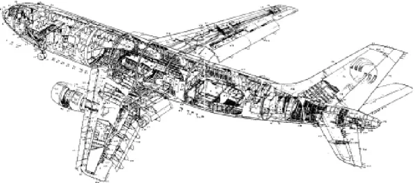
In this study attention is focused on the understanding of main structural effects related to the failure mechanisms and damage produced by the crashing of a high speed aircraft impact on the outer containment building of an innovative nuclear power plant. The airplane itself, built as an assemblage of ring and stringer-stiffened panels, is also subjected to gradual break-up and disintegration during the mentioned impact conditions.
The problem of interactive and progressive failure of a fast moving and deformable aircraft structure, i.e., the ergal/aluminum airframe into rigid and/or deformable bodies like a NPP outer containment building has not been addressed extensively in the literature.
Obviously, the effect of an aircraft crash and fuel explosion/burning on a NPP building would be subject to how each of the individual target buildings would perform under the impact and fire conditions.
The “impact” load, due to the effects of a finite amount of kinetic energy, which depends upon the inertial and stiffness properties of missile and target structure, differs from the “impulse” load that is generally a force independent of the inertial and stiffness properties of missile and target. Impact loads may result from tornado generated missiles, etc., whereas examples of impulse load are jet impingement effects in NPP structures.
As a result of the impact, (kinetic) energy is transferred from the aircraft to the building walls and absorbed by the building components in the form of strain energy whilst each component is deforming elastically and beyond up to the point of permanent yielding.
At the moment of impact the aircraft can be considered as a large but relatively ‘soft’ projectile which dissipates some fraction of the total kinetic energy through its deformation. After that some components of the aircraft sufficiently tough (assumed as rigid projectiles) will strike and in any case begin to penetrate the building walls.
In the performed analyses.
The preliminary simulation of the progressive impact of a civilian/military aircraft allows to determine the response of the structure, by equating the work done by the impacting load to the strain energy produced in the structures, applying the three basic principles of mechanics:
conservation of energy
conservation of linear momentum principle of virtual work
The energy conservation applies to the global scale of the entire aircraft and building, may be expressed through the following equation:
E kin = Ep + Eb (1)
where Ekin represents the initial kinetic energy of the aircraft (which is known) that is converted
into the energy dissipated by plastic deformation and fracture of the building structure (Eb) and
by the crushing and breakup of the aircraft structure (Ep).
It is important to note that some kinetic energy is also lost by friction and is converted into the elastic vibration of the entire building. This contribution is small and therefore may be considered negligible in the present analysis.
Moreover for each structural element, plastic energy is dissipated thought two mechanisms: the first mechanism is related to the plastic deformation through the tensile tearing or shear plugging mode, while the second one is related to the energy loss associated with the momentum transfer (both two mechanisms are depending on the impact velocity of the aircraft).
This study is intended to evaluate the structural effects, caused by an aircraft crash, and the capability to resist impact without relevant failure/damage (deflection, penetration, etc.) upon a typical outer containment of new generation NPPs.
2. Aircraft impact modelling
Protection of a NPP against aircraft impact relies upon strengthened containment of the reactor and other safety function buildings, together with wide physical separation of the safety systems and the enclosing building structures. The considered impact process is obviously a definite interaction between a very large stationary building and a small but fast moving airplane, both of which undergo considerable deformations.
The airplane disintegration process is also different in relation to which of its parts is under crashing. In the case of the fuselage and wings (“soft missile”) (Fig. 2), the local deformation starts immediately during the entry into the NPP outer containment wall and continues as the floors were cut and ripped apart; while in the case of the engines (“hard missile”) the deformation is reasonably small.
The fuselage consists of a system of rings and stringers attached to sheet metal. At this level of the first order engineering analysis, it is not possible to account for the individual contribution of rings, stringers, and the outer surface (skin). The engines are the only components of the aircraft that can be considered approximately as rigid bodies. Their devastating power is unmatched until they encounter an object of similar weight and strength.
In the experimental study in which an engine of a transport aircraft hit a thick concrete wall, the engine itself was crashed and fractured, so it was not enough rigid. Wings of modern commercial/civilian aircrafts are quite complicated structures constituting a very stiff and strong box-type section.
Moreover it is important to stress that the accident scenario may be influenced by the following parameters [4]:
Velocity and impact angles of the aircraft;
Mass and stiffness (function of the aircraft length), loading capacity, relative ductility of the target and of the aircraft;
Size and location of the impact area, which is dependent on the average impact angle (effective area is about 10000 - 40000 m2 with trajectory angles from 10°- 45° to the horizontal).
As for the aircraft impact concerned two categories of aircraft crash should be considered: the ‘design basis airplane crash’ which relates to the crash of a light airplane, although not defined in terms of mass and velocity, and the ‘design extension airplane crash’ which relates to both a military aircraft and a large civilian aircraft.
In the proposed evaluation of an aircraft crash on the outer NPP containment structure, the several following steps should be generally considered:
Global structural response, including excessive structural deformations or displacements, structure collapse or overturning (‘overall missile effects’) etc., particularly of the outer nuclear power plant containment and system or components located close to the outer walls, that depend to a large extent on the induced and propagated dynamic impact loads and other characteristics of the target subjected to impact (a particular situation may arise in the seismic isolated structures);
Localized structural damage due to the effects of missile impact, including penetration, perforation, scabbing etc., leading to the failure of a structural element as a result of the effects of primary (aircraft) and secondary missiles (engines and fuselage), which were originated from the initial aircraft failure (‘local effects’);
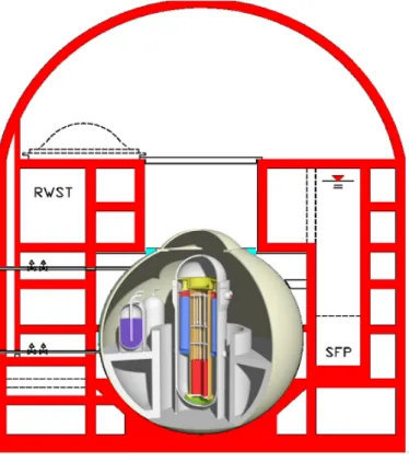
For the aim of the present study an innovative NPP reactor (e.g. like IRIS (Fig. 3) or ELSY, etc.) containment building, constituted of double barriers to resist the external and internal missile impact loads, was taken into account in order to evaluate the potential consequences/effects of an aircraft impact loading, mainly due to shear and bending, in the case of the perforation and
spalling of the concrete containment structure, as well as the propagation of shock waves and the global response of the considered structure itself that could impair the overall safety of the NPP.
Fig. 3 - IRIS NPP containment building
This problem is of strategic significance because the damage caused to the structure by these missiles might lead to the leakage of nuclear radiation.
The evaluation of the global dynamic behaviour of the whole building required the adoption of a deterministic approach to perform dynamic analyses to simulate effects and consequences of impact forces on NPP outer containment building, considering also the deformation that impacted area should undergo.
According to the IAEA rules if the only function of structures is to stop the aircraft and ensure the global stability of the building, they may be designed with plastic excursions of reinforced bars reaching ε = 2% deformation. Moreover for the design of a concrete barrier, the following criteria may be applied:
The impacting object may be assumed with characteristics similar to one of the heaviest engine of an aircraft (proved to be the worst scenario for the evaluation of local effects):
around 2000 kg of deformable mass travelling at 215 m/s, impacting on an area of 1.5 square metres in perpendicular direction to the external surface;
The concrete thickness may be chosen in the following range: 0.9 m to stop perforation of the missile, allowing significant scabbing on the internal surface, 1.6 m to avoid most of the scabbing, allowing only a limited amount of penetration;
Shear reinforcement (stirrups) proved to play an important role in the prevention of shear punching failures.
3. Global response evaluation
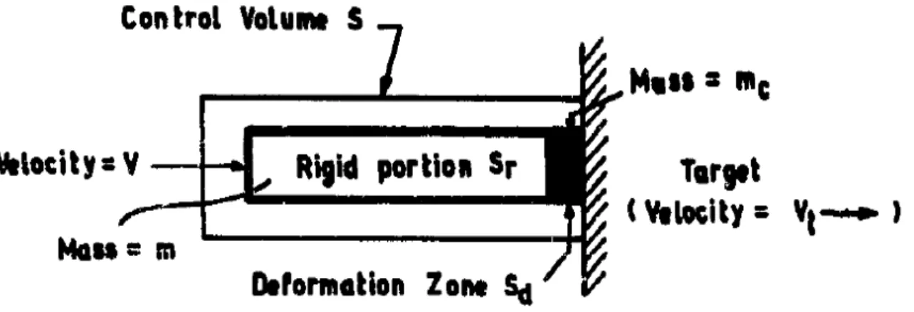
To analyze the global response of an outer containment building (CB) the first step has been to determine the impulsive loading function according to the Riera approach [6] (method already validated by experimental tests and computation [8-9]).
This approach assumes that the airplane could be represented like a soft missile, characterized by a thin deformation zone Sa and a rigid zone S, within a control volume S as shown in Fig. 4 [4],
striking a target.
Fig. 4 - Missile striking a target
As the projectile strikes the target, a part of it close to the target gets crushed and the remaining portion of projectile undergoes elastic deformation. The latter part from the point of view of deformation, may be regarded as rigid [10-11]. Therefore the following assumption should be made:
(1) The aircraft may be modelled as a one dimensional body that can yield only total force; (2) The missile axis and its flight trajectory coincide (i.e. straight flight path) and the impact is assumed to be normal;
(3) The crushed mass of the aircraft moves with the target structure.
On the basis of this assumption and applying the momentum equation to the projectile the reaction of target may be written as:
[ ]
(
)
dt t V c m mV d t x F ( ) = − (2)If the mass entering the deformation zone remains confined without any further change, then:
[ ]
dt c dm t V dt t dV c m dt dV m dt dm V t x F ( ) = + − − (3) Where:V and Vt are the velocities of the rigid portion of the missile and of target at time t;
m and mc are the masses of the rigid portion of the missile and its crushed mass;
m (dV/dt) is the force at the interface of the rigid and crushed regions.
the term (dmc/dt) is the rate of change in the mass of the crushed portion and is equal to µ[x(t)]
(V-Vt).
Moreover “…it can be seen that the rate of increase in the mass of the crushed portion is equal
in magnitude to the rate of decrease in the uncrushed portion of the missile. The negative sign in the values of m (dV/dt) and (dm/dt) signify that the velocity and mass of the rigid portion reduce with time…”[4].
The load necessary to crush or buckle a target may be expressed as:
[ ]
[ ] [ ]
dt t dV c m e V t x t x c P t x F ( ) = ( ) +µ ( ) 2(1− 2)+ (4) In Eq. 4:(dx/dt) indicates the velocity of the rigid portion relative to the target and is equal to (V-Vt);
(dm/dt) is the rate at which mass enters the deformation zone and is equal to µ[x(t)] (V-Vt);
µ[x(t)] is the mass per unit length of missile at a distance x(t) from the nose of the missile taken in uncrushed configuration,
“e” is a constant of proportionality between the velocity of rigid portion V and of the target V (i.e. Vt = e V) that will be zero for a rigid target.
The impact force, F(t), acting on the rigid fixed target calculated with the method developed by Riera [9], constituted by one term coming from the buckling and the other one from the inertial effect of the mass, becomes:
( )
[ ]
x( )
t m[ ] ( )
x( )
t[ ]
vt 2 c P t F = +α (5) In Eq. 5:Pc represents the load necessary to crush or buckle the fuselage;
x(t) the distance from the nose of the aircraft to the point up to which crushing has progressed at time, t;
m and v(t) are the longitudinal mass per unit length and the velocity of the uncrushed part of the aircraft;
α is an empirical correlation factor multiplying the effective mass on impact, which has been identified to 0.9 with an experimental F-4 Phantom impact [8].
In this preliminary study to determine the CB global response it has been used the “missile-target interaction method”, based on the inertial and stiffness characteristics of both the aircraft (impact velocity, aircraft length, crushing/buckling characteristics, etc.) and the target structures.
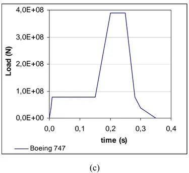
The dynamic response analysis of structure was carried out implementing the impact loading time-history method considering several types of military and large commercial airplanes and considering the effective impact area (e.g. equal to 37 m2 for the Boeing 707-320 [6]).
According to the IAEA safety guidelines [1], aircraft impact analyses were performed, in the case of mentioned normal direction strike into the CB outer walls, by uncoupling, as aforementioned, the missile and the rigid target structure surface and assuming different input load time functions, according to Riera method [12] (Figs. 5), which are representative of energy generated during the crash of a military and of a large commercial aircraft (such as the Phantom RF-4, the Boeing 707-320 etc.).
It is important to stress that the validity of Phantom RF-4 load time function (in terms of smoothed behaviour function as represented in the diagrams shown in Figs. 5) was verified by large scale tests in Sandia in 1988.
In the represented diagrams (selected load time functions for military jets as well as commercial/passenger aircrafts, the parameters of which are summarized in table I) the first peak
load is due to the crushing of airplane fuselage and was estimated applying similitude correlations (velocity, weight), whilst the second one, that is much more severe, is related to the following engines impacts.
0,0E+00 3,0E+07 6,0E+07 9,0E+07 1,2E+08 0,00 0,02 0,04 0,06 0,08 Time (s) Loa d ( N ) Phantom F4 (a) 0,0E+00 4,0E+07 8,0E+07 1,2E+08 0,0 0,1 0,2 0,3 0,4 time (s) Loa d ( N ) Boeing 707-320 (b)
0,0E+00 1,0E+08 2,0E+08 3,0E+08 4,0E+08 0,0 0,1 0,2 0,3 0,4 time (s) L o a d (N ) Boeing 747 (c)
Figs. 5 - Military jet (a) and civilian (b and c) aircraft impact Force Time History
Table I- Aircraft Parameters
Airplane type Mass at take off (Kg) Engine mass (Kg) Impact speed (m/s)
Phantom F4 ≈ 20000 2 x 1700 ≈ 215 Boeing 707-320 ≈ 150000 4 x 8100 ≈ 272 Boeing 747-200C ≈ 350000 4 x 21300 ≈ 269
Moreover it is important to highlight that the load function of Phantom and that one of Boeing, as 707 (like in EPR) or 747, might be used to design respectively the inner structures against induced vibrations, assuming a linear elastic material behaviour and the ultimate limit state in order to ensure that perforation is prevented and scabbing would not jeopardize the shutdown system of the reactor.
4. Numerical analysis
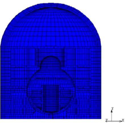
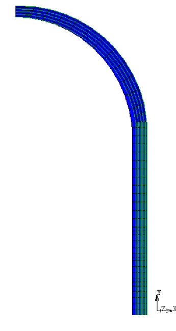
In the present study to evaluate the global dynamic response of CB structure a suitable finite element model (for instance the one of IRIS CB (Fig. 6)), and of considered (simplified) airplane (Fig. 7) was set up (adopting MSC© codes), assuming that the building was fixed at the foundation level.
Fig. 6 - NPP outer containment model
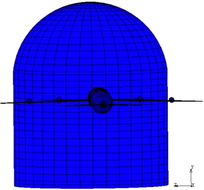
In the performed analyses a normal impact with airplane crashing from the front, like it is shown in Fig. 7, was chosen for the reason that it corresponds to the most unfavourable condition for the verification of the CB structural integrity and, at the same time, its structural response should be maximized in this condition.
Fig. 7 - View of aircraft impact direction
In the shown model, the outer CB walls are assumed to be built with reinforced concrete with reinforcing steel bars and pre-stressing tendons capable to undergo large deformations. The numerical model for the concrete structure is implemented with SOLID-3D 20 node elements and steel members (reinforcement and pre-stressed steel) are embedded as discrete bars, characterized by a uniform cross-section, by using 3D- TRUSS 2 node elements (their non-linear behaviour was dealt with appropriate elastic-perfectly plastic option).
In the set up outer containment model example, the total number of used element were about 44000.
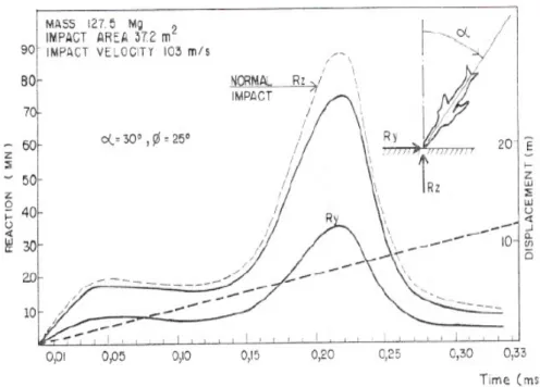
In the carried out analyses, the normal impact was chosen since it corresponds to the most unfavorable condition for CB structure (structural response should be maximized), according to Riera formulation (Fig. 8).
It was also assumed that the concrete may undergo gradual failure modes representing the progressive cracking and crushing of concrete itself caused by the abrupt stiffness changes (due to the propagation of the aircraft-missile kinetic energy). Moreover in the impact analysis, the damping effect was considered to be negligible as it does not affect the maximum response to impulse loading [3].
Fig. 8 – Riera structural response
Moreover in Fig. 9 it is shown the discretization and the normal impact location for the considered outer containment. The impact was assumed to be the most critical one and located in correspondence of the connection between the hemispherical roof and the cylindrical body.
Furthermore, longitudinal layers of reinforcing bars within the concrete CB walls are represented by smeared uniformly distributed layers of steel.
The thickness of these layers is determined by assuming that the cross-sectional areas of the reinforcing bars are spread uniformly along the respective pitch of the layers. The distribution of steel member reinforcement is indicated in Fig. 10, with green line inside and along the CB wall section.
Fig. 10 - Distribution of steel member reinforcement
The 3D-TRUSS 2 element, a six (6) degree of freedom element (i.e., three translation and rotational components at each node of the beam), was chosen to represent steel members
(reinforcement and pre-stressed steel), as aforementioned, in order to be capable to transmit moments, torque and axial forces.
Moreover this element has a uniform cross-section and is capable of undergoing large deformations and can model elastoplastic material response.
The material properties of rebars and studs used to reinforce CB walls are indicated in Table II and III.
Table II - Material properties of rebars
Density [Kg/m3] 7850
Young’s Modulus [MPa] 210000
Poisson Ratio 0.3
Yield Stress [MPa] 375
Tensile Strength [MPa] 621
Elongation to Fracture [%] > 14
Table III - Material properties of studs
Density [Kg/m3] 7850
Young’s Modulus [MPa] 200000
Poisson Ratio 0.3
Yield Stress [MPa] 345
5. Main results of numerical analyses
The impact of the Boeing 747 of course was observed to be more damaging than that of Phantom F4 (Figs. 11) for the reason that the energy transmitted during the crushing (the impact of fuselage has a duration time equal to about 0.2 s and 0.02 s, respectively for Boeing 747 and Phantom F4) resulted in an increase of the stress level in the reinforcing bars with maximum penetration depth in the impacted area of about 1 m in the case of the Boeing 747 and 0.3 m for the Phantom, as indicated in Figs. 11.
(a)
(b)
Figs. 11 - CB deformed shape subjected to Boeing 747 (a) and Phantom F4 (b) impacts It was also noted that in the impact area the global response of CB is characterized by a local penetration (Fig. 12 (a)), while the response away from the impact seemed to allow to ensure the stability and integrity of the structure itself, while, of course, the penetration depth was observed to be dependent on the type of aircraft considered, as shown in Fig. 12 (b).
0,0 0,2 0,4 0,6 0,8 1,0 1,2 0,00 0,05 0,10 0,15 0,20 Time (s) D isp la cem en t ( m )
impact area non impact area
0,00 0,20 0,40 0,60 0,80 1,00 1,20 0,00 0,05 0,10 0,15 0,20 Time (s) D isp la cemen t ( m ) 0,00 0,01 0,01 0,02 D isp lacem en t ( m ) P h an to m F 4 Boeing 720 Boeing 707 Boeing 747 Phantom F4 (b)
Figs 12 - Penetration depth:(a) in impacted/not impacted walls, (b) for different aircraft type Analysing the obtained results it was also observed that the energy transmitted during the crushing of Phantom F4, as an example, seemed to cause the progressive failure of concrete, localized in the impact area, and the increase up to yielding of steel rebars stresses (Fig. 13).
Rebar stress behaviour
0,0E+00 5,0E+07 1,0E+08 1,5E+08 0,0 0,1 0,2 0,3 Time (s) V o n M ise s str e ss (P a )
In addition the propagation of dynamic loading into the considered NPP did not determine relevant displacement that could trigger the internals structures, particularly the containment system as shown in Fig. 14.
Internal structure 0,0E+00 1,0E-03 2,0E-03 3,0E-03 0,00 0,05 0,10 0,15 0,20 Time (s) D isp la ce m e n t ( m )
Figs 14 – Displacement in correspondence of containment system
As for the induced stress due to the impact of a Boeing 747, it was observed that the crushing of the fuselage did not determine a penetration of the reinforced concrete of the outer CB walls (Fig.15 a), whilst the impact of rigid engine determined the progressive cracking of concrete coupled to the mentioned walls penetration (Fig. 15 b)
Furthermore a preliminary dynamic interaction/simulation of penetration effects (CB-crashing aircraft, e.g. Boeing 747) was also carried out, taking into account the aircraft speed and trajectory, materials behaviour, etc.
Moreover in Figures 16 (a) and (b) it were represented respectively the beginning of impact and of the penetration of the considered Boeing 747. The indicated Von Mises stresses behaviour seemed in agreement with those ones obtained by applying the Force Time History method.
(a)
(b)
(a)
(b)
The obtained results confirmed that the penetration (penetration depth of about 1m, like shown in Fig. 17), due to the engine impact) occurred and with the maximum stress intensity located in the impact area (Fig.12 (a)).
-1 -0,8 -0,6 -0,4 -0,2 0 0 0,1 0,2 0,3 0,4 Time (s) P e ne tr a tion D e pt h ( m )
Figs. 17 - Penetration analysis results: penetration depth
In general the stress values induced by the impact indicated that the structural failure of CB does not occur, even in presence of ongoing concrete progressive failure, due to the capacity of reinforcing steel rebar to provide adequate stiffness and load resistance to absorb the impact energy.
A sensitivity analysis was also carried out taking into account different containment wall thickness and reinforced/prestressed concrete characteristics.
The obtained results (not presented in this paper) indicated that if the outer CB wall thickness is less than 1 m (minimum value in agreement with the USNRC Commission recommendations) the impact of large commercial airplanes may determine the penetration and in any case the perforation of the exterior outer containment walls themselves.
6. Conclusion
In this study preliminary nonlinear analyses, simulating the horizontal impact (conservative approach) of commercial and military aircrafts on an innovative NPP containment structure, were performed in order to determine the global and local structural effects.
In the proposed study a deterministic methodological approach was proposed in order to correctly represent the influence of the assumed reactor building geometry on the propagation of dynamic loadings involving also consideration on the characteristics of the most important structural members that transfer the aircraft impact inertial loads from their application points to the internal nuclear relevant components.
The global response of the containment system was analysed by means of finite element codes (MSC.Marc and MSC.Dytran) that allowed to set up adequate even if simplified CB and aircraft models and taking into account the non linear material behaviour of concrete and reinforcing bars.
The obtained results (which were carried out analysing both the global aircraft impact and the dynamic CB-aircraft crashing interaction) highlighted that the outer containment wall will undergo local damage (penetration depth about 1 m for Boeing 747 and for the considered CB geometry). Moreover it was observed that away from the impact area the overall stability of containment structure seemed to be ensured.
Furthermore a sensitivity analysis was carried out taking into account different containment wall thickness and reinforced/prestressed concrete characteristics, highlighting that the impact of large commercial airplanes might determine in some cases the penetration of the exterior walls. It is worthy to stress that these results seem in good agreement with the wall thickness considered for the CB depth of present large Gen III+ NPP.
Finally the observed quite good agreement between the global and dynamic results seems to confirm the suitability of numerical approach with numerical codes, as the chosen one, to foresee and simulate the considered complex impact phenomenon in complex structures.
Future study developments of the aircraft impact, considering different trajectory angles and different structures seem necessary to correctly evaluate NPP containment system performances.
References
1. DOE-STD-3014-96, Accident Analysis for Aircraft Crash into Hazardous Facilities, 1996 2. IAEA “Safety Standard Series: External Events Excluding Earthquakes in the Design of
Nuclear Power Plants”, Safety Guide No. NS-G-1.5, 2003.
3. R. Lo Frano, G. Forasassi, Preliminary Evaluation of Aircraft Impact on a Near Term Nuclear Power Plant, Proceedings of the Intl Conference Nuclear Energy for New Europe, Bled, Slovenia, Sept. 14-17, 2009.
4. H. Abbas, D. K. Paul, P. N. Godbole, G. C. Nayak, ”Aircraft crash upon outer containment of nuclear power plant”, Nuclear Engineering and Design, 160, 199613–50.
5. ASCE, Manual No. 58 “Structural Analysis and Design of Nuclear Plant Facilities”, 1980, American Society of Civil Engineers.
6. J.D. Riera, “On the Stress Analysis of Structures Subjected to Aircraft Forces”, Nuclear Engineering and Design, 8, 1968, pp. 415–426.
7. C. Chelapati et al., ”Probabilistic assessment of aircraft hazard for nuclear power plants”,
Nuclear Engineering and Design, 19, 1972, 333–364.
8. Sugano, T., Tsubota, H., Kasai, Y., Koshika, N., Orui, S., von Risemann, W.A., Bickel, D.C., Parks, M.B., 1993c. Full-scale aircraft impact test for evaluation of impact force. Nucl. Eng. Des. 140, 373–385.
9. Wolf, J.P., Bucher, K.M., Skrikerud, P.E., 1976. Response of equipment subjected to aircraft impact. Nucl. Eng. Des. 47, 169–193.
10. K. Drittler, P. Gruner and J. Krivy, Calculation of forces arising from impacting projectiles upon yielding structures, 4th SMiRT, USA, Paper J 7/4, 1977.
11. J.D. Riera, A critical reappraisal of nuclear power plant safety against accidental aircraft impact, Nucl. Eng. Des. 57 (1980) 193-206.
12. J.D. Riera, “An approach to evaluate the Design Load Time History for Normal Engine Impact taking into account the crash-Velocity Distribution”, Nuclear Engineering and Design, 71, 1982, pp. 311-316.