Revision of the DEMO core configuration and of its dynamic behaviour
Descrittori
Tipologia del documento: Collocazione contrattuale:
Rapporto Tecnico
Accordo di programma ENEA-MSE: tema di ricerca "Nuovo nucleare da fissione"
Neutronica, Reattori nucleari veloci, Generation IV reactors
Argomenti trattati:
Sommario
The preliminary core design of DEMO, the Italian proposal for anindustrial demonstrator of Lead Fast Reactor, is here discusses and reviewed.
The idea of conceiving DEMO so as to be included in the LFR technology chain allows to focus on demonstration goals, abandoning therefore the goal of maximization of the neutron flux which drove the previous design.
The simplification of the design objectives allows the possibility of targeting a system responding to the so called "walk-away reactor" concept: a system able to respond autonomously and effectively to every possible accidental condition, guaranteeing the integrity of the containment without any human intervention from the outside. The palatability of such a possibility is even more evident after the well-known Fukushima events.
Note
REPORT LP3.E3a - PAR 2008-2009
Authors: G.Grasso, C. Petrovich
Copia n. In carico a: NOME 2 FIRMA NOME 1 FIRMA
NOME I G. Grasso P. Meloni P.Meloni
o
EMISSIONEfiRMA
c
r
f3?~
.-k
" REDAZIONETABLE OF CONTENTS
1 Introduction ... 3
2 Review of “GPS10” DEMO configuration ... 3
2.1 The “GPS10” DEMO core configuration ... 4
2.2 Review of the neutronic design of DEMO ... 6
2.3 Review of the dynamic behavior of DEMO ... 7
3 Derivation of the main characteristics for DEMO-revisited ... 7
3.1 Guidelines for the conceptualization of a new DEMO configuration ... 8
4 Conclusions ... 10
A Investigations on Tantalum transmutation ... 11
A.1 Model and tools ... 11
A.2 Simplified approach ... 12
A.3 Results ... 13
A.4 Approach verification ... 14
A.5 Conclusions on Ta transmutation ... 15
1 Introduction
This report deals with the critical revision of the design of the Technology Demonstration Project (DEMO) for a Lead Fast Reactor (LFR), already developed during the previous annuities of the “Accordo di Programma” between the Italian Ministry of Economic Development and ENEA [1, 2].
Lead Fast Reactors represent one of the possible options for the Generation IV reactors. Similarly to other fast reactor concepts, if the fuel is multi-recycled in a closed fuel cycle, it allows –with respect to standard Light Water Reactors in once-through cycles – to consume less uranium (reduction of a factor of ~200) and at the same time to produce less transuranic (Minor Actinides and Plutonium) as waste disposal (reduction of a factor of ~120) [3].
At the European level, a first LFR concept, with a thermal power of 1500 MWth, has been
investigated within the ELSY (European Lead-cooled SYstem) project [4, 5], financed by the VI Framework Programme.
In the VII Framework Programme the ELSY project found prosecution within the LEADER project (Lead-cooled European Advanced DEmonstration Reactor) [6], where both the
industrial plant (European Lead-cooled Fast Reactor, ELFR, 1500 MWth) and its demonstrator
(Advanced Lead-cooled Fast Reactor European Demonstrator, ALFRED, 300 MWth) are
currently being designed. Contrarily to the ELSY and DEMO designs, the choice of a hexagonal wrapped Fuel Assembly (FA) has been fixed in LEADER for both systems. This option has been established mainly for coherence with the CDT-MYRRHA project [7], which is assumed to represent the Technology Pilot Plant for the development of the LFR technology chain.
In view of the evolution of the ELSY project, and anticipating the need for a demonstrator of that reactor, the DEMO project has been set up few years ago, and the DEMO reactor conceived and designed. According to this, the system borrowed the main solutions and philosophies of the reference ELSY configuration, and in particular the wrapper-less, square FA: these solutions were assumed indeed before the LEADER project was started, thus before the overall design and particular solutions were changed.
This report deals with a critical revision of the DEMO core configuration [2], also in the light of the dynamic behaviors analysed in [8]. The revision will be focused also on a change in the philosophy driving the conception of the system, considering also the synergies and differences with ALFRED.
In appendix A, some investigating calculations on the neutronic impact of the use of Tantalum as coating material, are reported.
2 Review of “GPS10” DEMO configuration
The design of the “GPS10” configuration of DEMO [2] started from the study of the criteria that make possible the demonstration of a technology to the largest extent, under the aspects of:
• neutronics,
• thermal-hydraulics,
• system and component design, • safety and
• expected performances.
According to this philosophy, a demonstrator was intended as a reactor not only meant to prove the feasibility of the technology chain and the respect of the expected performances (in terms of both operation and safety), but also finalized to verifying the technological solutions to be implemented in an industrial power plant.
In that sense, the exercise of a demonstrator reactor should have had to provide all the information required to significantly reduce the design uncertainties, simplifying both the realization and the licensing process for the reactors of the same technology chain.
Anyway, that philosophy should be applied more to a Technology Pilot Plant (TPP) rather than to a demonstrator reactor: indeed, a demonstrator reactor should not be expected to provide data on specific aspects that could be analogously proven in a non-nuclear facility. On the other hand, a demonstrator should be intended as a system for proving overall features and the general behavior of the reactor itself.
According to this modified point of view and limiting the rationales to what concerns the core, the design of DEMO should be focused on the neutronics of the system itself.
Moving from this point, the demonstration of neutronics aspects lies on the verification of the evaluations for the main core parameters, made during the design phase: the exercise of the reactor will therefore provide the experimental evidences necessary for assessing the confidence level to be put on the methodologies and computational tools used to obtain these estimates.
2.1 The “GPS10” DEMO core configuration
The main goal targeted in the conception and design of DEMO has been the maximization of the neutron flux, so as to accelerate the reaching of the integral fluences required for irradiation experiments and tests. In order to get the highest possible flux, it was necessary to pursue simultaneously a maximization of the power density in the fuel, and a minimization of the Pu enrichment, trying to get a trade-off between the opposite adjustments.
The maximization of the power density has been obtained by applying a similar reduction to the linear power rating and the pin diameter (so as to preserve the radial temperature profile within the pin itself): if a reduction of some x % is applied to the pin diameter (and – proportionally – also to the clad and gap thickness, as well as to the pellet diameter), an analogous reduction of the same x % must be accordingly applied to the linear power rating to maintain the thermal profile within the pin. As a matter of fact, the reduced (by x %) linear power rating is now produced within a pellet whose cross-section is reduced of some 2x %: this implies the power density is increased by some x %.
The increase of the power density might be completely obtained by a proportional increase of the neutron flux whether the fuel enrichment is kept constant. However, the reduction of the pellet diameter implies a double reactivity loss: because of the reduction of the fuel inventory and because of the reduction of the fuel volume fraction in the elementary cell.
Targeting the maximum possible increase of the neutron flux (at least as high as the increase of the power density), it was chosen to maximize the core criticality by acting on the core configuration: at first, the coolant velocity has been set to the maximum allowed value, so as to minimize the coolant volume fraction in the elementary cell; then, following the same
strategy, the active height has been reduced, so as to further tighten the pin lattice (the shorter active length – the linear rating being fixed –, the lesser the integral power produced by the pin, thus the thinner the coolant channel around the fuel pins to remove the lesser power with the same coolant velocity). The latter operation – which may seem ineffective, implying a flattened core with increased leakage – has been adopted because it was found that the gain in reactivity due to the better material buckling of the system overtakes the reactivity loss due to the worst geometrical buckling.
The final DEMO configuration, as proposed in [2] and shown in Figure 1, is characterized by the parameters resumed in Table I.
Figure 1. DEMO configuration “GPS10”: inner (yellow) and outer (red) FAs surrounded by dummy elements (positions signed by the blue circle) within the Inner Vessel.
Table I. Main parameters of the present DEMO configuration
Parameter Unit Value
Thermal power MW 300
Active height cm 65.0
Pellet hollow radius mm 0.86
Pellet radius mm 2.55
Gap thickness mm 0.10
Clad thickness mm 0.35
Clad outer radius mm 3.00
Pins lattice pitch mm 8.53
Pins per FA - 28x28 - 6x6 - 4
FA side mm 238.84
Inner/Outer FAs number - 10 / 14
Inner/Outer Pu enrichment % 29.3 / 32.2
Fuel residence time month 20
Number of batches - 4
BoL/BoC/EoC keff - 1.10855 / 1.04088 / 1.00141
BoL/BoC/EoC FADF - 1.27 / 1.23 / 1.20
BoL/BoC/EoC maximul linear power rating W cm-1 393 / 381 / 371
BoC/EoC maximum neutron flux cm-2 s-1 7.27∙1015 / 7.54∙1015
Number of regulation/control FARs - 4 / 16 (2x8)
Worth of regulation FARs by partial (32.5 cm) insertion at BoC pcm 4083
Worth of regulation FARs by complete insertion at BoC pcm 9125
Worth of control FARs by complete insertion at BoC/EoC pcm 4624 / 4856
2.2 Review of the neutronic design of DEMO
The neutronic parameters of DEMO come directly from the optimization of its geometrical configuration, the latter being defined according to the general design philosophy assumed for targeting the overall objectives. All the features (and failings) of the present DEMO core follow directly or indirectly from the geometrical configuration of the core: for the critical review of the present configuration, the failings will be deeply analyzed in the following. At first, attention should be posed to the maximum velocity allowed for the coolant flowing through the core channels. The decision of increasing the allowed coolant velocity limit (from
2 to 3 m s−1, +50%) implied a significant increase of the pressure drops, both directly
(+125%) and indirectly (+50%) because of the contextual reduction of the coolant flow area. This implies a reassessment of the regime of nominal power removal by natural circulation during unprotected transients, leading the system to temperatures unacceptable for the integrity of the system itself.
The same problem comes from the choice of the pin pitch: comparing DEMO with ELSY, the pitch of the former system – chosen to remove the power of a 65 cm high core by a coolant
flowing at 3 m s−1 – would be the same of a core 42 cm high (less than one half of the ELSY
core) whether the coolant flow velocity would be set to 2 m s−1 as is in ELSY.
The choice of reducing the active height together with the reduction of the pin pitch – so as not to further increase the pressure drops – implies a series of consequences on the system:
+ the reactivity loss due to the more strewn geometry is more than compensated by the gain due to the lower volume fraction of the coolant in the elementary cell (as described in the previous section), allowing for a lower fuel enrichment;
+ the higher penetration of the “skin layer” into the core volume implies an increase of the leakage which, together with the small dimensions of the core itself, allow for an overall negative void effect;
– the lower enrichment (so the higher neutron flux, fixed the core power) and the higher leakage imply the need for a higher shielding of the core which, combined with the higher radial dimension of the latter, require an increase of the Inner Vessel (IV) diameter; in turn, a larger IV implies higher costs and risk of sloshing in case of earthquake;
+ the reduction of the active height allows for a narrower positioning of the core to the IV bottom, which determines a longer distance between the core and the Steam Generator (SG), which is the buoyancy chimney for the natural circulation of the coolant in unprotected transients.
The high enrichment required for achieving criticality implies also a low breeding, which in turn impacts directly on the high reactivity swing during the cycle. The control of the latter poses two opposite issues:
whether (as done in the DEMO configuration under analysis) a small number of
control rods (4 in the present configuration) are dedicated to the compensation of the over-criticality at Beginning of Cycle (BoC), the worth of each rod (some 1020 pcm) exceeds 1 $ (~330 pcm), so that in case of complete accidental extraction of one of these the reactor is brought to a over-prompt-criticality condition;
also whether the alternative compensation strategy – the use of a high number of
control rods – is adopted, only few positions are left for safety rods, so that it becomes impossible to guarantee the arrangement of two alternative and independent shutdown sets, required for the redundancy criteria of safety systems.
It is also important to point out that the fuel enrichment directly impacts the fissile inventory immobilized into the core, which in turn determines the number of critical masses available in case of core melt, causing possible re-criticality events.
The two issues described above suggest the need for achieving a more reactive configuration, which would allow keeping the fuel enrichment low.
2.3 Review of the dynamic behavior of DEMO
As expected, all the reactivity coefficients of DEMO – but the one related to the axial expansion of the core – are negative [2], including the coolant coefficient in the active zone because of the small size of the core. Despite that single positive coefficient, no reactivity transient brings the reactor to unstable conditions [8] thanks to the higher absolute value of the other negative coefficients.
An opposite consideration can be retrieved from the analysis of the behavior of the system during unprotected transients. In particular, the tight hydraulic channels in the core imply temperatures unacceptably high during Loss Of Flow transients, due to the need of sufficient prevalence (function of the temperature) to overtake the high pressure drops.
3 Derivation of the main characteristics for DEMO-revisited
In the light of the new design criteria discussed in section 2 and of the review of the current DEMO design, several considerations can be drawn in order to pave the way to a new design phase for the DEMO core. The new DEMO design, complying with the demonstration aim embedded in the name of the project itself, must face the twin LEADER (LEad-cooled
ADvanced European Reactor) project promoted in the frame of the 7th EURATOM
Framework Programme, complying with the design of a demonstrator (ALFRED: Advanced Lead-cooled Fast Reactor European Demonstrator) for the ELSY reactor.
The two reactors refer to the two different configurations of the same system.
ALFRED aims at demonstrating the viability of the so called “closed hexagonal”
ELSY configuration: developed by SCK●CEN and chosen as backup option in the ELSY project, then assumed as reference for the ELFR (European Lead-cooled Fast Reactor) – the industrial plant investigated in the LEADER project –, is characterized
by traditional1 Fuel Assemblies (FA) made of a hexagonal lattice of pins enclosed in a steel wrapper.
DEMO refers to the s.c. “open square” configuration: developed by ENEA and chosen
as reference option in the ELSY project, is characterized by standard2 FAs made of a
square lattice of pins without any tube portioning the coolant flow through the core so as to allow for cross-flows throughout the core.
The two systems share therefore the same overall technology as well as the main system concept to be demonstrated. They also share the same power and many technological constraints (hence also several parameters as the pellet, gap and clad radii). In the frame of the LFR technology chain, they also rely on the experience coming from the exercise of MYRRHA, playing the role of TPP.
Nevertheless, the two demonstrators are not to be intended anyhow as alternative to each other: as a matter of fact, ALFRED will represent the demonstrator for an industrial reactor which can be expected available in the short-term, while DEMO – implementing all the innovative solutions investigated in the ELSY project together with other brand new ideas – should pave the way for a further development of the LFR technology chain, demonstrating the viability of a second generation of industrial reactors, more performing and optimized than the former ones, to be industrialized in the long-term.
3.1 Guidelines for the conceptualization of a new DEMO configuration
At first, as widely discussed in the previous section and in the light of the role played by MYRRHA in the LFR technology chain, DEMO should be intended now as a pure demonstrator: hence, the need for a high neutron flux loses meaning.
The loss of this main goal, which drove the first design of DEMO, allows foregoing the research for the exasperated optimization of that configuration: the extreme hypotheses of
600 °C as peak clad temperature and 3 m s−1 as maximum coolant velocity through the core
can be therefore abandoned.
The reduction of the maximum clad temperature to 550 °C – being fixed the maximum fuel temperature – imposes to increase the clad diameter from 6 to 10.5 mm (the same of the ELSY fuel pin, since the technological constraints become the same). This, in turn, allows the increase of the fuel inventory in each pin, reducing the need for a high enrichment of the fuel for the criticality of the system.
The possibility of reducing the fuel enrichment whets the designer curiosity for checking out whether the configuration is conceivable so as to allow the adiabatic operation of the reactor, i.e.: in a closed cycle, only fed by depleted uranium [3]. To achieve such a goal one has to lower the Pu enrichment from the 29-32% values of the “GPS10” configuration towards the 17%-18% values obtained in ELSY [3]. Being the adiabaticity one of the main features of ELSY, the above mentioned possibility would allow DEMO to serve also as demonstrator of the viability of such an interesting and promising fuel management strategy, mainly to what concerns the operability of a reactor with equilibrium content of Minor Actinides.
The reduction of the maximum coolant velocity to 2 m s−1 requires an increase of the coolant
flow area, hence of the pin lattice pitch. On one hand, the increased pitch reduces the
1
For fast reactors. 2
reactivity of the elementary cell, to the detriment of the fuel enrichment; however, on the other hand, the wider geometry allows relying on lesser pressure drops for the coolant flowing through the core, encouraging the beginning of natural circulation in case of unprotected transients.
Being the latter a killing point for the licensing of a system (in particular after the Fukushima events), it could worth assuming an even larger pin pitch, so as to further encourage the natural circulation regime, targeting in this way a system inspired to the s.c. “walk-away reactor” concept. It is obvious that such an attractive goal conflicts directly with the reactivity of the elementary cell, hence on the enrichment required for achieving the criticality of the reactor.
The two attractive possibilities (the adiabaticity and the “walk-away reactor” concept) suggest the research for a trade-off between their opposite design requirements. A promising strategy to get the required trade-off is surely represented by the shortening of the active height, as widely discussed in the previous sections.
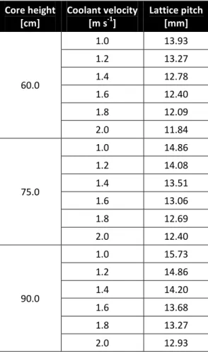
According to this, and assuming an overall power/Pin Distribution Factor (PDF) equal to 1.3 and a realistic axial form factor of 1.15, it is possible to anticipate a parametric dimensioning of the coolant channel as a function of the coolant flow velocity for various core heights, as shown in Table II.
Table II. Parametric investigation of the coolant flow area as a function of coolant velocity through the core for various core heights
Core height [cm] Coolant velocity [m s-1] Lattice pitch [mm] 60.0 1.0 13.93 1.2 13.27 1.4 12.78 1.6 12.40 1.8 12.09 2.0 11.84 75.0 1.0 14.86 1.2 14.08 1.4 13.51 1.6 13.06 1.8 12.69 2.0 12.40 90.0 1.0 15.73 1.2 14.86 1.4 14.20 1.6 13.68 1.8 13.27 2.0 12.93
The result of this parametric analysis will be used in the forthcoming conceptualization and design of DEMO-revisited.
4 Conclusions
The revision of the existing DEMO configuration has been here presented. Beyond the analysis of the main issues, an overall discussion about the design philosophy that drove the design of DEMO has been conducted. In particular, the idea of conceiving DEMO so as to be included in the LFR technology chain allows focusing on demonstration goals, abandoning therefore the goal of maximization of the neutron flux which exasperated the design of the GPS10 configuration of DEMO.
The simplification of the design criteria suggests the possibility of targeting a twofold objective: a system responding to the so called “walk-away reactor” concept, able to be operated as adiabatic. The palatability of such a system justifies the efforts that will be demanded to conciliate the opposite requirements implied by the two single goals: low pressure drops through the core and high reactivity of the latter, respectively.
Finally, the active height shortening strategy is indicated as promising for achieving such goals in a new DEMO configuration to be investigated and characterized in the forthcoming future.
A Investigations on Tantalum transmutation
One of the still open issues for the LFR is the method to avoid corrosion on the structural materials in lead environment. In the frame of the LEADER project, as alternative to the GESA treatment [9] developed by the Karlsruhe Institute of Technology (KIT), the use of Tantalum as coating material for T91 has been proposed. This option is currently under investigation by ENEA-Brasimone.
A drawback of this choice is that Tantalum absorbs neutrons: the nuclear reaction chain is
181
Ta (n,γ) 182Ta, which β-decays (T1/2=114.7 days) into 182W.
This has mainly 2 impacts:
The neutron economy in the reactor is worsened and has to be compensated by a
higher Pu enrichment of the MOX fuel;
part of the Tantalum is transmuted into Tungsten. This issue has been raised in the
WP2 meeting of the LEADER project [10] and can also be found in literature (for example in [11], [12], [16]).
The transmutation may result in the accumulation of transmutation products, which could be detrimental for the engineering properties.
The objective of this appendix is to better quantify the amount of Tantalum transmuting into Tungsten during the irradiation residence time of the cladding in the core (about 5 years).
A.1 Model and tools
The neutronic calculations have been performed not in the DEMO configuration but in the
ELSY configuration (1500 MWth, 3 enrichments zones), in the “open-square” option [5] at
Beginning-Of-Life.
The assumed thicknesses for the cladding are:
550 μm of T91;
50 μm of Ta.
The exact thicknesses have not yet been fixed in the design and these values are only representative for investigating neutronic calculations.
The calculations are here performed by means of the transport code MCNPX 2.7.a [13] and of the activation code FISPACT 2001 [14].
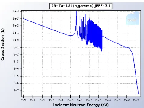
The neutron cross-sections used for Ta in MCNPX are the Jeff 3.1 at 700 K [15].
As shown in Figure 2, the 181Ta capture cross-section is higher for thermal energy, but it
maintains values over 0.1 barn also at neutron energies typical of the ELSY reactor, that are
Figure 2. 181Ta capture-cross section.
A.2 Simplified approach
With 50 μm of Ta thickness, the total impact of Tantalum absorptions onto keff turns out to be
of:
Δkeff = -4830 pcm.
This has to be compensated by a higher Pu enrichment of the MOX fuel (for example from about 22% to about 24%).
Taking into account only the number of atoms of 181Ta (not considering 182Ta) and the capture
reactions, the number N of atoms of 181Ta can be approximately expressed as:
N(t) = N0e(-ac t),
where:
N0 is the number of atoms of 181Ta at time 0,
ϕ is the average neutron flux in the considered volume [cm-2
s-1],
σac is the 181Ta 1-group capture cross-section [cm2], flux-weighted averaged
(σac = ʃ ϕ(E) σc(E) / ϕ). σac is strongly dependent on the neutron spectrum and is higher
with softer spectra.
With this simplified approach, the transmutation quantity of 181Ta depends only on the
product ϕ σac.
With the aim of scoping calculations, we have evaluated the values for ϕ and σac in the
claddings in 5 zones:
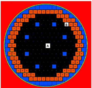
in the fuel assembly in the centre part of the core (see Figure 3, label A);
average values in the inner core zone (cladding in 56 FA);
average values in the intermediate core zone (cladding in 50 FA);
average values in the outer core zone (cladding in 56 FA).
Figure 3. ELSY core and FA where the calculations have been performed (A in the centre of the core; B in the periphery of the core).
A.3 Results
The values of ϕ and σac are reported in Table III, together with the corresponding values of
(N0-N(t))/N0), representing the amount of Tantalum which has been transmuted (simplified
approach). The time t considered is t = 5 years because this is about the residence time of the FA to reach 100 GWd/ton.
Table III. Values of neutron flux and Ta 1-group cross-section in different part of the core
Φ [cm-2 s-1] σac [barn] (N0-N(t))/N0 [%] Central FA 8.821014 0.93 12% Peripheral FA 1.181015 0.98 17% Inner zone 1.151015 0.90 15% Interm. zone 1.501015 0.81 17% Outer zone 1.321015 0.87 17%
The values of ϕ and σac have been computed also at different heights (along the 90 cm active
height) and at different core zones. The analysis shows maximum values of ϕ and σac in the
active zone respectively of 3.71015 cm-2 s-1 and 2 barns.
The amount of Ta transmutations in the cladding in the active zone turns out to be on the average of 16% and is here evaluated to be at maximum of about 30%.
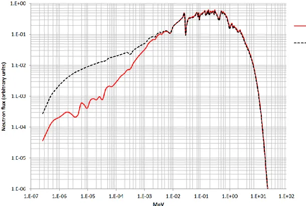
This amount is lower than the transmutation values reported in [10]. The reason is that the presence of Tantalum in the cladding changes the neutron spectrum, decreasing the part below 1 keV, where the values of the capture cross-sections are higher (this is the “self-shielding
effect” [11]). Therefore the spectrum hardens and the value of σac becomes lower.
Only a detailed neutron transport calculation can show this effect. To verify this interpretation, the calculations have been repeated without the presence of Tantalum. Figure 4 shows the neutron spectra in the claddings in the 2 different situations.
Figure 4. Neutron spectrum in the T91 and Ta cladding in the outer core zone.
Table IV shows the impact to the average 1-group cross-sections due to differences in the spectrum with and without Tantalum.
Table IV. 181Ta capture cross-sections averaged in the spectrum with and without Tantalum
σac [barn] with Ta (real situation) σac [barn] without Ta (approximate situation) Inner zone 0.90 4.14 Interm. Zone 0.81 3.44 Outer zone 0.87 3.53
A.4 Approach verification
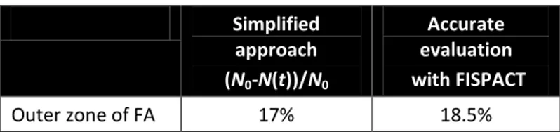
To verify the adopted simplified approach, a FISPACT calculation has been performed for the
into account, but also 182Ta decays, 182Ta captures and all other minor neutron interactions. The result is shown in Table V.
The detailed FISPACT calculation shows that, starting for example from 1000 g of Tantalum, 186 g of Tungsten are formed after 5 years (then 35 mg of Hf and 8 mg of Re).
Table V. Values of Ta transmutations in the outer zone of the core Simplified approach (N0-N(t))/N0 Accurate evaluation with FISPACT Outer zone of FA 17% 18.5%
Therefore the simplified approach is here verified for this system.
A.5 Conclusions on Ta transmutation
It is confirmed that Ta undergoes transmutation towards W in a high neutron flux. The amount of these transmutations is strongly dependent on the value of the neutron flux and on the neutron spectrum. Therefore the exact transmutation rates depend on the real LFR design and on the axial and the radial position of the Tantalum material under investigation.
If Tantalum is used as coating for the cladding in a LFR core, it can be estimated that in the active zone, after 5 years (approximate residence time of the FA to reach 100 GWd/ton), the transmutations towards (mainly) Tungsten turns out to be on the average of 16% and at maximum of about 30%.
Further estimations would be appropriate to evaluate the transmutations outside the active zone.
References
[1] S. Bortot, C. Artioli and G. Grasso. Preliminary proposal for an ELSY-oriented
Technology Demonstration Project (DEMO). Technical Report FPN-P9LU-041, ENEA, July 2009.
[2] G. Grasso et al. Static/dynamic DEMO core characterization. Technical Report
NNFISS-LP3-003, ENEA-CIRTEN, September 2010.
[3] C. Artioli, G. Grasso and C. Petrovich. A new paradigm for core design aimed at the
sustainability of nuclear energy: The solution of the extended equilibrium state. Ann.
of Nucl. En. 37:915-922 (2010).
[4] ELSY Work Programme. The European Lead-cooled System (ELSY) project.
EURATOM, contract no. FP-036439, Management of Radioactive Waste - 6th Framework Programme, 2006.
[5] M. Sarotto et al. ELSY core design static, dynamic and safety parameters with the
open square FA. Technical Report ELSY-DEL/09/008, EURATOM, ENEA FPN-P9IX-006, May 2009.
[6] LEADER (Lead-cooled European Advanced DEmonstration Reactor), Annex I –
“Description of Work”, Grant agreement no.: FP7-249668, Small or Medium-Scale Focused Project, 2010.
[7] MYRRHA, 2011 MYRRHA website – www.sckcen.be/myrrha.
[8] S. Bortot et al. Sviluppo di un modello di dinamica di nocciolo per un DEMO LFR.
Technical Report CIRTEN-POLIMI RL 1138/2010, RdS/2010/110,
CIRTEN/ENEA/UNIBO, September 2010.
[9] A. Weisenburger et al. Corrosion, Al containing corrosion barriers and mechanical
properties of steels foreseen as structural materials in liquid lead alloy cooled nuclear systems. Nucl. Eng. and Design 241:1329-1334 (2011).
[10] Minutes of the WP2 LEADER meeting, Genova 10th May 2011, ENEA.
[11] C. B. A. Forty, G. J. Butterworth and J.-Ch. Sublet. Burnup of some refractory metals
in a fusion neutron spectrum. J. of Nucl. Mat. 212-215:640-643 (1994).
[12] M. R. Gilbert, J.-Ch. Sublet, Neutron-induced transmutation effects in W and W-alloys
in a fusion environment, Nucl. Fusion 51 (2011), doi:10.1088/0029-5515/51/4/043005.
[13] D. B. Pelowitz et al. MCNPX 2.7.A Extensions. Technical Report LA-UR-08-07182,
LANL, November 2008.
[14] R. A. Forrest. FISPACT-2001: User manual. Technical Report UKAEA FUS 450,
EURATOM/UKAEA Fusion Association, Culham Science Centre (UK), 2001.
[15] A. Koning et al. The JEFF–3.1 Nuclear Data Library, JEFF Report 21, OECD
2006/NEA No. 6190, ISBN 92-64-02314-3.
[16] G. A. Cottrell, Sigma phase formation in irradiated tungsten, tantalum and
molybdenum in a fusion power plant, Journal of Nuclear Materials 334 (2004)
166-168.