Development of best estimate numerical tools for LFR
design and safety analysis
Descrittori
Tipologia del documento:
Rapporto Tecnico
Collocazione contrattuale:
Accordo di programma ENEA-MSE su sicurezza nucleare
e Reattori di IV generazione
Argomenti trattati:
Reattori Nucleari Veloci, Termoidraulica dei reattori nucleari
Sicurezza nucleare, Analisi incidentale
Sommario
Nell’ambito della linea LP2, sono state condotte attività di ricerca al fine di sviluppare, aggiornare e convalidare codici di calcolo e modelli numerici per sostenere la progettazione ed effettuare analisi di sicurezza di un reattore veloce refrigerato a metallo liquido. Nell’ambito del PAR 2016, sono state messe in atto delle azioni al fine di integrare e coordinare tali attività. Si sono, pertanto, definite le aree di simulazione e le interconnessioni rilevanti per la progettazione e sicurezza di reattori Gen-IV. Ognuna di queste aree di simulazione è coperta da uno o più codici e simula un set di fenomeni multi-fisica e multi-scala rilevanti, e.g. termoidraulica di sistema, di contenimento, di sotto-canale, fluidodinamica tridimensionale, termo-meccanica della barretta di combustibile, del fuel assembly e di componenti, generazione di sezioni d’urto e sviluppo di metodi di aggiustamento delle stesse mediante utilizzo di dati sperimentali, dinamica neutronica tridimensionale, rilascio e trasporto di prodotti di fissione, etc. Tale attività servirà come base di partenza per un’azione di sviluppo e convalida di una piattaforma di calcolo per sistemi nucleari innovativi, che si protrarrà nel PT2015- 2017 (e successivi). Pertanto, si propone di procedere con l’attività secondo la seguente logica:
- definire le aree di simulazione e le interconnessioni rilevanti per la progettazione e sicurezza di reattori Gen-IV; - definire i codici e la piattaforma di accoppiamento e identificare le necessità di sviluppo e lo stato di convalida; - procedere con l’attività di sviluppo, convalida e applicazione in continuità con quanto fatto negli ultimi anni. Relativamente a sviluppo e convalida, riportate nella parte 2 del presente report, sono state effettuate attività relative a:
1. termo-meccanica della barretta di combustibile – supporto allo sviluppo del codice TRANSURANUS. 2. accoppiamento codici CFD/SYS-TH e loro validazione a fronte delle campagre sperimentali TALL e CIRCE 3. termoidraulica di sistema – supporto alla validazione del codice REALP5-3D per applicazione ai sistemi a piscina 4. dinamica accoppiata neutronica-termoidraulica tridimensionale - sviluppo e applicazione codice FRENETIC 5. modellazione multifisica neutronica – termoidraulica - accoppiamento OpenFoam-Serpent
6. dinamica molecolare per lo studio di fenomeni di diffusione nella interazione combustibile refrigerante
7. termoidraulica multifluid/multiphase e analisi di incidenti severi – supporto allo sviluppo e alla vlidazione del codice SIMMER-III e -IV
Note:
--Autori: A. Del Nevo, A. Cervone, G. Grasso, M. Tarantino (ENEA); T. Barani, A. Cammi, M. Cerini, S. Cervino, L. Cognini, L. De Luca, L. Luzzi, M. Giola E. Macerata, M. Mariani, S. Lorenzi, D. Pizzocri, (POLIMI); R. Bonifetto, D. Caron, S. Dulla, P. Ravetto, L. Savoldi, R. Zanino (POLITO); L. Chirco, R. Da Vià, S. Manservisi (UNIBO); G. Caruso, M. Frullini, F. Giannetti, V. Narcisi, A. Subioli (UNIROMA1) M. Angelucci, G. Barone, N. Forgione, R. Lo Frano, A. Pesetti, C. Ulissi (UNIPI)
Copia n. In carico a:
1
NOMEL
IST OF
R
EVISIONS
Revision Date Scope of revision Page
DEVELOPMENT OF BEST ESTIMATE
NUMERICAL TOOLS
FOR LFR DESIGN AND SAFETY ANALYSIS
L
IST OF CONTENTS
LIST OF REVISIONS ... 3
LIST OF FIGURES ... 9
LIST OF TABLES ... 10
LIST OF ABBREVIATIONS ... 11
1
INTRODUCTORY REMARKS ... 13
1.1 Objectives ... 132
DESIGN AND SAFETY ANALYSIS AREAS IN SUPPORT OF
LEAD-COOLED
FAST
REACTOR DEVELOPMENT ... 15
3
CHARACTERIZATION OF THE MODELING NEEDS FOR THE SELECTED AREAS ... 17
3.1 Core Design ... 20
3.1.1 Thermal-hydraulics ... 21
3.1.2 Thermo-mechanics ... 22
3.1.3 Neutronics ... 23
3.1.4 A possible platform layout (limited to core design activities) ... 24
3.2 Primary system design R&D development needs ... 25
3.2.1 Identification of the key topics for the LFR development ... 25
3.2.2 LFR material studies and coolant physical-chemistry ... 25
3.2.3 LFR studies of Core integrity, moving mechanisms, instrumentation, maintenance, in service inspection and repair ... 28
3.2.4 Steam Generator functionality and safety experimental studies... 29
3.2.5 Thermal hydraulics ... 31
3.2.6 HLM pump and corrosion/erosion studies ... 33
3.2.7 Instrumentations ... 33
3.2.8 Fuel and Irradiation Testing ... 35
3.2.9 Hot laboratories capabilities and needs ... 37
3.2.10 Neutronics ... 38
3.3 Auxiliary and ancillary systems design ... 39
3.3.1 Decay heat removal system ... 39
3.3.2 Fuel handling system for core assembly loading and unloading, irradiated fuel cooling during transfer and transport to the irradiated fuel pool ... 40
3.3.3 Other auxiliary systems ... 40
3.5.2 Complements for the PSA application in a safety analysis ... 44
3.5.3 PSA application in preliminary safety analysis ... 44
3.5.4 ISAM methodology ... 44
3.5.5 PSA modelling needs ... 45
3.6 Deterministic Safety Analysis ... 45
4
OVERVIEW OF THE MODELING ACTIVITIES IN 2016 (PART 2) ... 55
L
IST OF FIGURES
Fig. 1 – 3D cut view of the ALFRED reactor. ... 14
Fig. 2 – Iterative process of reactor configuration development ... 16
Fig. 3 – Hypothetical relation between complexity and accuracy of a model. ... 50
Fig. 4 – LFR core design process with the main physical interconnections highlighted. ... 50
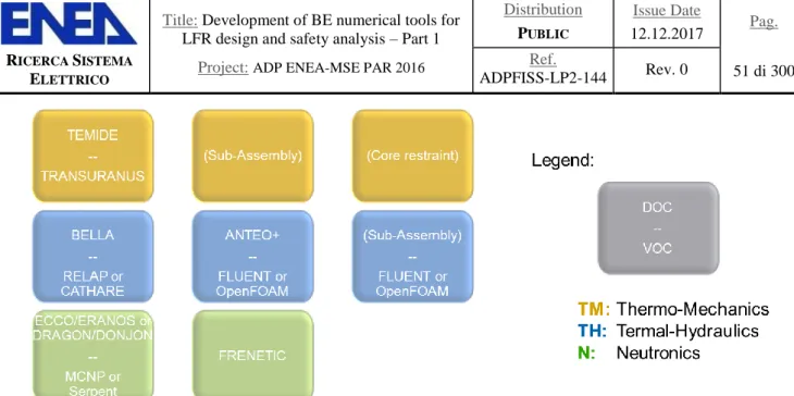
Fig. 5 – List of candidate codes for the aimed core design/verification platform. ... 51
Fig. 6 – Simplified coupling scheme for thermal-hydraulics feedback evaluation in design. ... 51
Fig. 7 – Detailed coupling scheme for thermal-hydraulics feedback evaluation in design. ... 51
Fig. 8 – Detailed coupling scheme for thermal-hydraulics feedback evaluation in verification. ... 52
Fig. 9 – Platform utilization in the case of core restraint design. ... 52
Fig. 10 – Configuration of the operational control system in terms of functions (please note the connection with protection and limitation systems [18] ... 53
Fig. 11 – Control strategy road map. ... 53
Fig. 12 – Different approaches in modelling, 0D/1D modelling (control-oriented) vs 3D modelling (design-oriented). ... 54
L
IST OF TABLES
Tab. 1 – ALFRED specifications. ... 14
Tab. 2 – Aspects encompassed in the design and verification of main reactor sub-systems (N: Neutronics; TH: Thermal-Hydraulics; TM: Thermo-Mechanics; C: Chemistry; E: Electronics). ... 16
Tab. 3 – Aspects encompassed in the design of core components(N: Neutronics; TH: Thermal-Hydraulics; TM: Thermo-Mechanics).. ... 48
Tab. 4 – Main features and differences between causal and acausal approach. ... 48
Tab. 5 – Summary of available instrumentations. ... 48
Tab. 6 – Summary of the European zero power reactors. ... 49
Tab. 7 – EUR Design Basis Category. ... 49
Tab. 8 – Options for Combination of a Computer Code and Input Data[32]. ... 49
Tab. 9 – Development, validation and application of computational tools: summary of the activity performed in the framework of PAR-2016. ... 55
L
IST OF ABBREVIATIONS
AdP Accordo di Programma
ALFRED Advanced Lead Fast Reactor European Demonstrator
ATHENA Advanced Thermal Hydraulic Experiment for Nuclear Application
BE Best Estimate
BEPU Best Estimate Plus Uncertainty
BoP Balance of Plant
BoT Beginning of Transient
CEA Commissariat a l'Energie Atomique et aux Energies Alternatives
CFD Computational Fluid Dynamics
CIRCE Circolazione Eutettico
CIRTEN Interuniversity Consortium for Technological Nuclear Research
CHEOPEIII Chemistry Operation III Facility
CR Control Rod
DBA Design Base Accident
DHR Decay Heat Removal
DHRS Decay Heat Removal System
DOC Design-Oriented Code
DSA Deterministic Safety Analysis
ESFRI European Strategy Forum on Research Infrastructures
EoT End of Transient
FA Fuel Assembly
FALCON Fostering ALFRED Construction
FPC Fuel Performace Code
FR Fast Reactor
GIORDI Grid to Rod fretting facility
HBS High Burnup Structure
HELENA Heavy Liquid Metal Experimental Loop for Advanced Nuclear Applications
HLM Heavy Liquid Metal
HX or HEX Heat Exchanger
I&C Instrumentation and Control
LBE Lead Bismuth Eutectic
LECOR Lead Corrosion Loop
LEADER Lead-cooled Advanced Demonstration Reactor
LIFUS5 Lead-Lithium for Fusion Facility (5)
LFR Lead Fast Reactor
LM Liquid Metal
LMR Liquid Metal Reactor
LWR Light Water Reactor
MA Minor Actinide
MABB Minor Actinides Bearing Blankets
MOX (U-Pu) Mixed Oxide
NACIE Natural Circulation Experiment Loop
NPPs Nuclear Power Plants
O&M Operation and Maintenance
OPEX Operating EXperience
POLIMI Politecnico di Milano
POLITO Politecnico di Torino
PP Primary Pump
PSA Probabilistic Safety Analysis
RACHELE Reactions and Advanced chemistry for Lead
RSE Ricerca Sistema Elettrico
RV Reactor Vessel
RVACS Reactor Vessel Air-Cooling System
SA Safety Analysis
SET-PLAN Strategic Energy Technology Plan
SG Steam Generator
SGTR Steam Generator Tube Rupture
SISO Single Input Single Output
SYS System
SYS-TH System- ThermalHydraulics
TH Thermal-Hydraulics
TKE Turbulent Kinetic Energy
TRL Technological Readiness Level
TSO Technical Safety Organization
ULOF Unprotected Loss of Flow
UNIBO Università di Bologna
UNIPI Università di Pisa
UNIROMA1 Università di Roma - Sapienza
VOC Verification-Oriented Code
1 I
NTRODUCTORY REMARKSThe Lead-cooled Fast Reactor (LFR) technology brings about the possibility of fully complying with all the Generation IV requirements[1]. This capability being more and more acknowledged in international fora, the LFR is gathering a continuously increasing interest, with new industrial actors committing on LFR-related initiatives.
In this context, the Italian nuclear community evaluates strategic to continue elevating the competences and capabilities, with the perspective of extending the support to the design and safety analysis of future LFR systems.
The most appropriate framework for this advancement is the Accordo di Programma (AdP), within which ENEA and CIRTEN (the consortium gathering all Italian universities engaged in nuclear education, training and research) are already cooperating on the LFR technology since 2006, along with national industry as main stakeholder.
Within the AdP, the LFR system chosen as reference for all studies and investigations is ALFRED, the Advanced Lead-cooled Fast Reactor European Demonstrator [2]. As a demonstration reactor, indeed, it was reckoned as the system best fitting with the research and development (R&D) nature of the activities performed in the AdP, being demonstration the step that logically follows R&D in the advancement of the LFR technology by readiness levels. Moreover, ALFRED is envisaged as the key facility of a distributed research infrastructure of pan-European interest [3], open to scientists and technologists for relevant experiments to be performed on a fully LFR-representative and integral environment, with the long-term perspective of supporting to the safe and sustainable operation of future LFRs, thereby fulfilling the general objectives of the AdP itself.
The collaborative spirit behind the development of ALFRED is an inherent trademark of the project since its very beginning. As a matter of facts, it was originally conceived and initially developed within the LEADER (Lead- cooled European Advanced Demonstration Reactor) collaborative research project [4], co-funded by the European Commission through the 7th EURATOM Framework Programme. After the conclusion of the LEADER project, the Fostering ALFRED Construction (FALCON) International Consortium was signed between Ansaldo Nucleare, ENEA and the Romanian research organization RATEN-ICN with the twofold objective of further developing the ALFRED design and of performing all the strategic, managerial, and financial activities required to set the consortium prepared for the realization of ALFRED in Romania [5]. A view of the ALFRED reactor block layout, and the main parameters of the reactor, as resulting at the conclusion of the LEADER project, are shown in Fig. 1 and Tab. 1, respectively.
1.1 Objectives
In the wide spectrum of possible activities to support the further development of the LFR technology, and exploiting the specific expertise acquired by the universities in the past years, within the scope of the 2016 Piano Annuale di Realizzazione (PAR) it was decided to focus the cooperative efforts shared between ENEA and CIRTEN towards the development of an best estimate computational tools supporting the various stages of design and safety analyses of LFR systems, so to increase – or help in viewing how to fill the gaps – the modeling capabilities.
The first step in this process, which is also the objective planned for the first year of activity and accordingly included in the PAR2016, is thus to define what are the most important modelling needs and fundamental features that the desired platform and its tools should possess. This will permit, on one hand, to derive guidelines for the selection of tools to be embedded in the platform (should they exist), or for their development wherever a remarkable gap is found between the codes in the present landscape and those envisaged for the platform; on the other, to retrieve guidelines for the development of the integration platform hosting and managing the execution of the identified tools.
Reactor specification
Thermal power (MW) 300
Fuel residence time (years) 5
Coolant inlet temperature (°C) 400
Average coolant outlet temperature (°C) 480 Coolant mass flow rate (kg s-1) ≈ 25700 Average coolant velocity (m s-1) ≈ 1.4
2 D
ESIGN AND SAFETY ANALYSIS AREAS IN SUPPORT OFL
EAD-
COOLEDF
ASTR
EACTOR DEVELOPMENTDesign is, very generally, the discipline aiming at determining the main parameters which unequivocally define a reactor configuration providing the desired performances while targeting all the desired performances and complying with all the constraints, both in nominal and accidental conditions. Given the very different nature of the performances and constraints, and the multidisciplinary essence of the task, reactor design is principally an art of engineering compromise and harmonization.
Conversely, verification is the discipline aiming at determining the actual behavior of a reactor configuration, both in nominal and accidental conditions, so as to evaluate the extent to which performances have been achieved and constraints respected. Given the relevance of verification, notably when addressing the safety aspects of a reactor, the confidence on the obtained results is the principal objective of this task. Generally speaking, design and verification are the two sides of the same coin: while design translates target performances and constraints into a reactor configuration, verification analyzes the latter to retrieve the actual performances expressed, and constraints respected, by the configuration, eventually providing feedbacks to the design stage for optimization. In developing a reactor configuration (Fig. 2), these two activities are therefore iteratively performed until convergence is reached, with the final reactor configuration performing as desired and fulfilling all the imposed constraints.
The apparent symmetry between design and verification is broken by the interface with safety authorities, for the certification of the reactor configuration obtained at the end of the iterative process. Licensing has indeed so strict rules, and is so a fundamental objective, to practically impose all verification activities during the iterative process to be performed with the same rules, and possibly codes, of the certification phase (the only possible most notable difference being the quality assurance requirements needed for fully complying with the safety authority demands during the licensing process, both from a software and analysis management procedures point of views). Design instead moves in a more free domain, thereby remaining the sole phase, in the development of a new reactor configuration, where actions to optimize the iterative process can be deployed.
The development of new LFR systems must fulfill all the objectives put forward by the GIF [1]. Extending the Generation IV safety philosophy also to the other areas (economics, sustainability, proliferation resistance and physical protection), provisions are to be “built in” the design, rather than “added to” configurations not yet scoring as aimed. As a matter of facts, this approach not only guarantees the fulfillment of the goals, but also top-scoring effectiveness and robustness, along with design simplicity, which is an asset for reliability and economics itself. For provisions to be built in, all the aimed performances and constraints are to be considered from early design stages, which is compatible with the degree of freedom of the design phase mentioned above.
Practically, this implies achieving the target objectives by a proper combination of materials and design, in which the latter comes in aid when the former ends. In the specific case of LFRs such a process involves the examination of all lead properties so that all weaknesses are coped with, while all advantages are exploited. The design is then set orienting choices so to take profit of inherent features, thus making it more robust and the chosen configuration either directly target-embedding, or compatible with the achievement of the goals; finally, should any objective be not fulfilled, complementing engineering provisions can be easily foreseen.
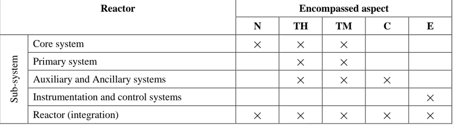
The second main aspect defining the requirements for design and safety analysis is the complexity of a reactor. Like a human body, it is indeed a complex system, made of several sub-systems (apparatuses), in turn made of several components (organs); all these components and sub-systems differ in nature, but are altogether strictly interfaced and interdependent: the design and verification of a reactor, therefore, has to take into account the performances and constraints not only of every single component by itself, nor just of the single sub-systems, but also of the entire reactor as a whole. Moreover, for each component – and even more so for each sub-system – a number of analyses (during both design and verification) are required on different fields. In Tab. 2, an overview of the aspects encompassed in the design and verification of the main reactor sub-systems is presented.
Reactor Encompassed aspect
N TH TM C E Sub -sy st em Core system
×
×
×
Primary system×
×
Auxiliary and Ancillary systems
×
×
×
Instrumentation and control systems
×
Reactor (integration)
×
×
×
×
×
Tab. 2 – Aspects encompassed in the design and verification of main reactor sub-systems (N: Neutronics; TH: Thermal-Hydraulics; TM: Thermo-Mechanics;
3 C
HARACTERIZATION OF THE MODELING NEEDS FOR THE SELECTED AREASThe primary characteristic of the aimed platform is to effectively support the decision-making process. In practical terms, this can be translated in bringing to fruition the benefits of a rationale design or verification approach – logically the opposite of the trial-and-error one. Appropriate tools should be developed for each component or sub-system, and differentiated, wherever appropriate, depending on their application during the design or verification phase. It is worth stressing the fact that differentiating design- and verification-oriented tools – besides the trivial benefit of optimizing each for the aimed purpose – has also the additional benefit of domain separation, that allows a double, independent check of the design aspects, which is in line with all safety recommendations and best practices.
The last statement also defines the general philosophy for the development of the aimed platform in response to the modeling needs. Whilst specific requirements will be addressed in the following subsections, the general needs for tools of analysis in support to the design and verification, according to the specificities of these phases, are introduced.
Design-Oriented Tools
During the design phase, little or no information is available on the object itself of the design. Several scoping analyses are usually performed to down-select (screening) candidate options among all the possible ones. Corrective actions are often required to account for the impact of some aspects – related to one or more parameters – on the other parameters.
All these things put together, a computational tool effectively supporting the design process has to possess a number of instrumental features like:
equilibrium,
low computational times and
a clear application domain.
A code satisfying these prerequisites is called a Design-Oriented Code (DOC)[6]. It is also worth mentioning that these characteristics are synergistic, in the sense that they point in the same direction and, as such, they can effectively be met together. In the following, each of the mentioned features of a DOC will be discussed in more detail.
Equilibrium
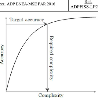
With equilibrium it is intended a good balance between the ability of the code in reproducing experimental data on one side, and, on the other, the complexity of the implemented models and overall structure so to maintain a clear relationship among the various system parameters. It should therefore represent an clear improvement over analytical methods for what concerns accuracy and possibilities, while still keeping their clarity in relating constraints/performances to core parameters. This objective is believed to be crucial, since a very complex tool would hinder the user’s understanding of the system under study, while an inaccurate one would render unusable or less significant the results, reducing the confidence of the user in utilizing them.
To better illustrate this concept, it can be assumed that the curve relating accuracy with model complexity – in the form of degree of completeness of the phenomena description – has the form reported in Fig. 2; the
Even if vaguely introduced, the term “satisfactory accuracy” has actually a precise meaning. Equilibrium, indeed, also means that the various sources, contributing to the overall uncertainties, are balanced so to avoid excessive efforts to increase accuracy on terms that are already poorly contributing to the uncertainty on the final results. The terms in questions can be essentially divided in three categories:
1. input data
in terms of quality (and quantity) of the available input parameters; a DOC should indeed require a level of input detail fitting with the current design stage. Many input values are often not yet known and only a rough first estimate is usable in the early design stages; for such kind of parameters an extremely accurate (and thus complex) tool would be oversized, besides hindering the understanding of the relation between performances/constraints and configuration.
2. material properties
in terms of the only approximate knowledge stemming from measurement campaigns or the difficulty in reproducing particular conditions (e.g., irradiation effects, modification of the chemical environment). Depending on the specific physical field covered by the DOC under development, material properties can contribute significantly to the final uncertainties.
3. models
in terms of modeling errors; is the one directly under control of the DOC developer. Reducing this error, as previously discussed (see Fig. 3 – Hypothetical relation between complexity and accuracy of a model.
4. ), implies a stronger modeling effort and thus code complexity. The contribution of this term should then be balanced with the effect of the other two so to avoid the coupling of a very refined and time consuming model with poor material properties or input data. This will enforce code homogeneity and modeling efficiency, both helping in keeping clear the link between performances/constraints and the resulting configuration.
Low computational times
While it is true that a DOC can help in understanding the features of the system being designed, due the non-bijective relation between the geometric configuration and the performances/constraints, a complete knowledge can never be achieved. This means that a DOC can help in rationally orienting choices for setting up a coherent configuration, but such a process would remain tentative in nature. Due to this, it could be desirable to test a number of configuration options and, as such, a DOC should be fast running with a low computational burden. Moreover, a sensitivity analysis could be performed to span the operational phase-space looking for quantitative correlations substantiating intuitive optimization strategies or for understanding safety margins in key parameters; since these are all generally time consuming tasks, short computational times must be pursued.
Clear application domain
To enhance confidence in the DOC results, simplifying their interpretation phase – necessary in a rational design process –, to facilitate Verification and Validation (V&V) activities, and to enable a clear comprehension of the calculation flow by the user, the application and validity domain must be openly
If the path of an a priori selection of the application range is not fully followed, the developer should at least make any effort engineeringly possible to make it as clear as possible.
Verification-Oriented Tools
During the verification phase, detailed information is available on the designed object. Single simulations are sufficient to evaluate each and every specific aspect whose knowledge is required. High-fidelity results are mandatory in response to the simulations, notably concerning safety-related aspects.
All these things put together, and proceeding in parallel with the previously discussed DOC characteristics, a computational tool effectively supporting the verification process has to possess a number of instrumental features like:
accuracy,
reasonable computational times and
quality assurance.
A code satisfying these prerequisites is called a verification-Oriented Code (VOC)[6]. In the following, each of the mentioned features of a VOC will be discussed in more detail.
Accuracy
The equilibrium requirement, for a VOC, is substituted by accuracy; a VOC indeed is meant at affording a higher degree of complexity (see Fig. 3) and at losing clarity in the name of accuracy. During the verification stage the system is fully characterized by the previous design phase and with the maximum degree of input information available; the real hindrance towards accuracy are bound to be material properties.
Reasonable computational times
Computational times, similarly to a DOC, should be as low as possible. Again in the name of accuracy, however, the increase of computational times can be afforded if this entails an increased precision. Compatibly with the available resources, and for those physical fields in which achieving considerable accuracy would require prohibitive computational times, techniques for refining only the more complex regions of the system while modeling in a simplified way their interconnections could be exploited.
Quality assurance
A point which is diriment for VOCs used in safety analysis for licensing purposes is the Software Quality Assurance (SQA). SQA is ideally important also for DOCs, but becomes mandatory for VOCs which produce results to be submitted to the safety authorities. When developing a VOC, therefore, all the best practices for managing the SQA must be put forward, significantly increasing the development effort as a whole; this is a strong incentive in moving towards already available qualified tools which, unfortunately, are generally not open source.
SQA plays also an indirect role when, during development, a strong level of accuracy is pursued, as this almost certainly increases code complexity. Indeed, SQA becomes increasingly more difficult to manage for complex software, making the development process more expensive in term of human resources. This can be another consideration to take into account when performing a weighted decision for selecting an already existing code or starting development from scratch.
Integration platform
A. to tackle the multi-physics, multi-scale and heterogeneous nature of the problem at hand, the platform must include a variety of codes, each responsible for one specific physical aspect and scale; ideally, even for the same aspect, different levels of modeling and computational complexity should be present so to make the platform more ductile relatively to the user needs;
B. versatility must be pursued, meaning the ability to move from the necessities of a user design-oriented to the ones of a user verification-oriented so to support in full the LFR development chain;
C. similarly to the previous requirement, inside the specific domain, be it design or verification, the possibility of freely and selectively (as much as physically and engineeringly possible) linking the available tools should be present, enabling the user to carry out specific tasks using the desired amount of complexity, from a physical, modeling and computational resources point of view;
D. the flow of information between codes, handled by the platform, should be as efficient and clear as possible, to simplify the user understanding of the problem and aiding the final results interpretation phase, of the utmost importance in any rational endeavor;
E. adding tools to the platform should be as easy as possible, helping in reducing the interface development time for any new tool to be added;
F. to increase system portability and appeal, reliance on open software must be pursued as much as practicable. This requirement can battle with the need for qualified software accepted by safety authorities in the case of licensing applications, making the selection of codes and points A and C of this list non-trivial tasks.
3.1 Core Design
The design of the core is typically the first step in the process of developing a new reactor configuration. For the core, all the general arguments discussed in Sect. 2 hold; are anyhow worth mentioning, to complete the picture of this discipline, the heavily multi-physic, multi-scale and strongly heterogeneous aspects involved in this specific task.
Due to the central role of core design, the philosophy adopted by the Italian research community gravitates around the concept of “holistic design approach”, somehow anticipated in Sect. 2, that is: the inclusion of all the target constraints and performances deeply within the process, so as to set a final configuration fulfilling all these goals by-design. This approach permits also to develop approaches adjusted so as to permit the optimization of the iterative process, even accounting for the strict verification rules.
Due to the strong complexity of the problem, however, this simple statement to be put in practice requires mastering the process of translation of all the aforementioned constraints and performances – a priori known – in relations among the geometric, material and physical parameters defining a core configuration. As a matter of facts, the perfect, quantitative knowledge of these relations is the only key for the designer to properly setting-up a system configuration complying with all the requirements. Such relations can sometimes originate from experience or from the use of simple physical/empirical correlations; due however to the heavy interdependence among the many multi-physical, multi-scale and very different aspects encompassed in the core design, dedicated tools suitably developed as DOCs can be of great aid.
The logical scheme of the process of core design according to the holistic approach is also shown in Fig. 4 specifically for the case of an LFR.
The aspects encompassed in core design, along with examples of their application to the core components and proposed tools meant for inclusion in the simulation platform for supporting their design, are briefly discussed in the following subsections.
3.1.1 Thermal-hydraulics
Elementary cell
The elementary cell design is heavily guided by thermal-hydraulics considerations: apart from the minimum operating temperature which is fixed by the margin to coolant freezing, all the upper bounds are actually established by the ability of the steel structures to safely operate in a lead environment, meaning to limit corrosion processes to acceptable levels. The elementary cell must therefore be sized to guarantee the respect of the clad temperature constraint – allowing also for uncertainty margins – and to limit coolant velocity and the consequent erosion dynamics. Another important, safety-related objective is to assure the onset of natural circulation at affordable temperatures; this is particularly important in the case of a Loss Of Flow (LOF) accident (notably under Unprotected conditions – ULOF) in order to avoid excessive cladding temperatures and the risk of a short time creep failure or even melting. To achieve this, low pressure drops through the fuel bundle are necessary; and a suitable dimensioning of the elementary cell must therefore be pursued.
Proposed software:
To aid the designer in this process, simplified codes able to simulate the dynamic behavior of the core in supposed transients can be used. The BELLA code[7] is an existing tool possibly fitting this role, especially for the safety-related part, since it features the DOC characteristics, being able to simplify the problem description while preserving the salient relationship between the physical quantities of interest. Indeed it is a simplified tool acting as a bridge with system codes and so naturally suited for implementing the safety-informed design approach mandatory for Gen-IV systems.
For the verification phase, no specific code is required for the elementary cell, as its analysis is included in general system studies.
Sub-assembly (S/A)
The main objective during the S/A thermal-hydraulic sizing is to guarantee a uniform radial profile of the coolant temperature and adequate cooling for all the pins in the bundle. This is important, especially, for enclosed Fuel Assembly (FA) concepts. The primary objective is to avoid local hot spots, cold by-passes and to reduce thermal gradients which could create unwanted mechanical stresses. The pressure drops through the main components of the S/A such as spacers, foot and any other relevant area change or narrow paths must also be such that the benefits of a wide elementary cell are not overshadowed by excessive pressure losses in other S/A components. From the safety point of view, the threat of a flow blockage due to cooling channel plugging via corrosion/erosion products sedimentation, coolant solidification or any foreseeable occlusion agent must be prevented as much as practicable, or mitigated in the residual cases.
Proposed software:
To this aim the sub-channel code ANTEO+ [8] could be efficiently used, since it has been specifically developed following the guidelines of a DOC as discussed in Sect. 3. ANTEO+ has also been extensively validated making its use during the design phase even more meaningful with the concrete possibility of assessing uncertainties on the main quantity of interest so to allow for sufficient margins.
For validation purposes, the punctual analysis of specific aspects can be investigated by means of Computational Fluid Dynamics (CFD) codes as FLUENT [9] (or any other commercial code) or OpenFOAM [10], the former having the robustness and maturity of commercial codes, the latter the openness to modifications as required, being open-source.
Core
The core thermal-hydraulic design is, in a way, similar to the FA one; cold by-passes must be avoided, especially in the case closed FAs are used, but, at the same time, excessive thermal gradients among opposite faces of the FA ducts prevented. This means assuring a suitable coolant flow outside the FAs themselves, which has to be determined according to the inter-assemblies gap, established by the thermo-mechanical design. If a wrapped FA is used, the possibility of gagging arises, giving an extra degree of freedom to the designer for actually leveling thermal gradients at the FA outlet. During the core thermal-hydraulic design, the amount of pressure drops necessary to balance the coolant flow with the FA power must be calculated and a gagging zoning proposed so to achieve a lifetime optimum configuration, while still keeping low fabrication costs.
Proposed software:
No DOCs are available in the open literature to support the thermal-hydraulic design of an LFR core. For the by-pass problem, the development of a specifically dedicated tool has already been planned. For the gagging problem, due to the relevant connection with the FA and by-pass problems, it is sought a coupling between the future by-pass DOC with ANTEO+ to perform all the needed analyses.
For the validation of the by-pass, the same CFD tools presented for the FA problem can be envisaged. Concerning the gagging problem, as for the elementary cell case, no specific tool is required, the analysis being part of general system studies.
3.1.2 Thermo-mechanics
Pin
The pin thermo-mechanic design is aimed at ensuring on one hand that the fuel temperature be lower than the melting one, allowing margins for uncertainties, in nominal and accidental conditions (with particular regard to the Unprotected Transient of Over-Power – UTOP); on the other hand, at assuring the integrity of the cladding via its ability to withstand both the internal pin pressure, arising from gas release due to fission (in fuel pins) or boron captures (in absorber pins), and pellet-clad mechanical interactions stemming from swelling, thermal expansion and cracking of the pellet. Being in particular the fuel pin cladding the first engineered barrier against the dispersion of radioactivity, ensuring its integrity is of paramount importance in the overall design process.
Proposed software:
To what concerns the pin design, the TEMIDE code [6] can be employed on the platform, since it has been specifically developed for fuel pins following the DOC guidelines discussed in Sect. 3, and is also undergoing a preliminary validation.
For validation purposes, no available code has undergone the requested extensive validation, as experimental information on pins irradiated in fast spectrum are not so abundant in the open literature. However,
bowing, must be avoided or at least limited to acceptable values; this also includes the spacing means used to form the bundle, which have to restrain the pins while preventing (or reducing below the threshold for significant fretting) flow-induced vibrations. The structural skeleton of the S/A also has to provide the stiffness required for core stability and safe handling.
Proposed software:
This particular field is presently poorly covered and no DOC is available for inclusion in the platform; this suggests that for further advancing LFR projects development, work on this sector should be a priority. Due to the very peculiar nature of the phenomena to be accounted for, it is questionable that existing codes for thermo-mechanic analysis (such as ANSYS [12]) can be applied to the extent required for validation purposes.
Core
The mechanical core design is strongly related to the mechanical design of the S/A. The collective behavior of the S/As under the actions of differential bowing can generate forces to be managed to ensure core integrity and the possibility of S/A handling; conversely, if gaps are allowed between the S/As to avoid contact forces, the possibility for positive reactivity insertion due to compaction appears, which is to be avoided or reduced to manageable values. The restraint of the core is achieved by properly designing the S/A support structures (upper and lower core plates, where present), the S/A structural skeleton and the structure perimetering the core (barrel).
Proposed software:
In complete analogy to the previous paragraph, no DOC is actually available, nor VOC fully applicable, for such tasks and competences in this field should be strengthen in the Italian framework.
3.1.3 Neutronics
Core
The main purposes of the core neutronic design involve i) the definition of the fuel enrichment and/or enrichment zoning which guarantee the operability of the reactor for the foreseen time span, respecting all the constraints on the maximum burn-up along with requirements on the cladding and fuel temperatures; ii) the sizing and positioning of redundant, diverse and independent banks of control and safety rods, able to manage any reactivity excursion during normal operation (from startup/shutdown to criticality swing and power excursions) and emergency. On the fringes of the core neutronic design, there is the evaluation of the core reactivity coefficients so to allow safety analysis and dynamic studies to be performed. Although LFRs, thanks to the huge margins offered by the coolant, usually present a very forgiving behavior in accidental conditions, it could be the case that the optimization of the reactivity coefficients enters the core design process, mainly at the level of neutronics (even if also thermo-mechanics and thermal-hydraulics play important roles).
Proposed software:
To achieve all the mentioned objectives the code ERANOS [13] could be used, since specifically developed for fast reactors and with intentions going in the direction of a DOC. Moreover, the two-steps approach – with cells and core calculations – is still the most suited (in many cases) for preliminary design evaluations. The main limitation of ERANOS is its non-open-source nature; an alternative in this sense could be the DRAGON/DONJON suite [14]. These tools, although not strictly DOCs nor powerful as ERANOS, are one rare example of open-source software in the deterministic neutronics field.
MCNP [15] outstands for the level of development and validation, even though its use is restricted by export control rules. Alternatively, Serpent [16], although less mature, can be considered as open-source code.
Shielding
Shielding analysis, mostly dealing with neutronics (or better, radiation transport), has the twofold objective of i) ensuring that the radiation-induced damage to the reactor structures remains below acceptable limits; ii) ensuring that the radiation levels in all the premises of the reactor (especially if human access is considered) remain below the limits set for radiation protection.
Proposed software:
Shielding analysis is an activity for which design and verification phases typically merge together. For close-to-the-core analyses (e.g., structural damage), coupled deterministic and Monte Carlo codes can be used, to facilitate the latter in defining effective variance reduction approaches; for analyses far from the active zone (e.g., radiation protection), Monte Carlo codes by themselves are typically used. All the codes listed in the previous paragraph can be used as well for the purpose of shielding.
3.1.4 A possible platform layout (limited to core design activities)
Putting together all the requirements for the complete design and verification of the reactor core, and considering the codes available or to be developed to fill emerged gaps that were listed in the previous subsections, it is possible to draft a preliminary layout of the aimed platform, at least for what concerns the core. The general layout of the platform to what concerns core design/verification is shown in Fig. 5.
According to the presented taxonomy, some possible utilizations of the platform are qualitatively illustrated in the following.
Neutronic analysis with thermal-hydraulic feedback
The impact of the temperature field on the core neutronics, meaning criticality and power distribution, plays a non-negligible role, and has to be investigated to understand how much the power flattening effect resulting from the thermal feedback can help in reducing gradients and hot spots inside the core.
In the supposed platform, the problem could be tackled in a variety of ways, each with an increasing level of detail or focusing on a particular facet of the problem at hand. Having as reference Fig. 5, the following calculation schemes and interconnections could be exploited for design purposes:
1. As depicted in Fig. 6 a simplified approach based on a cell code (ECCO or DRAGON) and the core code FRENETIC[17] can be elaborated. The cell code is used to compute the macroscopic cross sections for a particular thermal state; these information are then passed to FRENETIC which computes the overall power distribution and, on this basis, a lumped-values the temperature field in the fuel, structures and coolant. At this point the new thermal state at each S/A level is passed back to the cell code to update the cross sections matrix. The process is repeated until convergence. 2. A more elaborate and complete scheme could also be used by switching from FRENETIC to the core
sub-and respectively: from ECCO/ERANOS or DRAGON/DONJON to MCNP or Serpent for the transport solution, from ANTEO+ to Fluent or OpenFOAM for the thermal field in the coolant, and from TEMIDE to TRANSURANUS for the thermal field in the fuel, obtaining the new, equivalent scheme shown in Fig. 8. Core restrain system design
To present the power of such a platform, one of the most complex calculation schemes is here presented, concerning the design of the core radial restraint, as it encompasses the neutronic, mechanic and thermal-hydraulic fields. A possible code correlation is shown in Fig. 9: the power distribution computed by the neutronic DOC is given to thermal-hydraulic tools at both sub-channel and by-pass level in order to retrieve the main temperature field in the whole core; this information is then used by the thermo-mechanic codes at pin, S/A and core level to understand the radial and axial deformations of the components in order to provide relevant information to properly design the restraining system.
3.2 Primary system design R&D development needs
3.2.1 Identification of the key topics for the LFR developmentR&D efforts are necessary for completing the design, support the pre-licensing and starting with the construction of such systems. Such activities require the identification of the technological gaps, which are design dependent, and the key topics for LFR developments. The LFR technological issues have been divided into the following main topics[25]-[31]:
Material studies and coolant physical-chemistry;
Studies of core integrity, moving mechanisms, instrumentation, maintenance, in service inspection and repair;
Steam Generator functionality and safety experimental studies; Thermal-hydraulics;
HLM pump reliability; Instrumentations;
Advanced fuels and Irradiation Testing; Neutronics;
3.2.2 LFR material studies and coolant physical-chemistry
Corrosion by liquid metal
Corrosion of structural materials in lead is the main issue for the design of LFR. The topic is related to lifetime limits and circuit design. The following sub-issues are considered:
Corrosion in Lead of fuel cladding, vessel, reactor internals, components, and heat exchangers;
Corrosion at high temperatures (related to development for long term perspectives); Corrosion of pump impeller materials;
Corrosion inhibitors development (i.e. coating);
on medium/long term corrosion behaviour in flowing lead. The following list of facilities is available for investigating heavy liquid metals corrosion at ENEA:
- LECOR (ENEA), Tmax= 500°C, vmax= 1 m/s, fluid Pb - HELENA (ENEA), Tmax= 500°C, vmax= 2 m/s, fluid Pb
A specific Pb loop able to achieve higher temperature (at least 650°C) and 2 m/s is still missing and is identified as potential required infrastructure to cover long term development of the technology as well as to perform specific tests under particular conditions (i.e. DBA).
Embrittlement and degradation of structures by liquid metal
The condition represents the lower bound of mechanical properties of liquid metal exposed materials. It consists in the reduction of fracture toughness and of ductility of un-irradiated materials after long term exposure to lead.
It is necessary to experience and to standardize (in order to be reproduced with a typical standard procedure) tests with respect to:
LME, fatigue, creep,
stress corrosion cracking, and fretting in HLM.
These experiments are necessary and must be conducted in testing machines where the specimens are exposed to the liquid metal effect, both static and flowing tests. There is only one facility available at ENEA for investigating fretting of structures by liquid metal:
• GIORDI (ENEA), Tmax=550°C, Pb and LBE
Pb facilities devoted to the investigation of embrittlement, fatigue, creep SCC up to 650°C in liquid metal, under oxygen control are still missing and represent required infrastructures.
High temperature materials for long term perspectives
Full development of GEN IV programmes foresees the future increase of reactors operating temperatures (beyond 550 °C). This evolution is aimed to enhance the thermodynamic efficiency and to allow the association of side energy production efficient processes. This challenging goal requires, to test:
“new” materials such as ODS steels, refractory alloys, SiC composites, “MAX” phase materials;
coated materials as developed by GESA treatment, PLD (@IIT), CVD-Ta. The testing conditions are:
Currently test can be performed by the RACHELE laboratory (ENEA) with these conditions in stagnant HLM. Since the existing facilities for corrosion testing are not able to achieve 650-800°C in flowing lead, new infrastructures are necessary to meet these requirements.
Irradiation effects on materials
The reactor pressure vessel, the structural materials, the internals and the fuel cladding are subjected, with different extent, to several degradation mechanisms such as neutron irradiation, thermal ageing and corrosion. In case of HLM systems, research activities are generally aiming at understanding, quantifying and predicting such effects on critical components of a nuclear power plant. Focus is given on the performances of the materials in terms of (neutron irradiation induced) embrittlement, on the behavior of stress corrosion, as well as neutron irradiation induced effects such as creep and swelling. The main objective is to determine whether or not irradiation will promote embrittlement and corrosion attack by HLM.
The current status of knowledge is not completely addressed, and more experimental investigations are needed, providing high quality data on the material behavior. It is expected that assessments of fuel cladding and structural core materials, subjected to both high temperature in a lead environment and fast flux, are critical issues.
Summarizing the following main issues on irradiation performance of candidate materials are of primarily importance for LFR systems development:
Corrosion in HLM under irradiation (coated and uncoated material); Irradiation embrittlement of selected materials;
Irradiation creep; Swelling.
The effects of irradiation on materials is a critical issues for LFR system development. The experimental infrastructure needed to address these issues are currently available irradiation machines and research reactors.
Impeller pump materials
The relatively high speed between structural material and HLM implies that the pump impellers are subjected to severe corrosion-erosion conditions that might not be sustained in the long term. Tests are planned on specimens of materials. The materials of the pump impeller have to satisfy a couple of demanding requirements which deserve specific experimental installation:
capability to withstand to an exposure to high temperature lead (up to 480°C, and higher for long term perspective);
capability to withstand to corrosion/erosion effects due to high relative coolant velocity (10 m/s, and up to 20m/s);
demonstration of reliability and performances of the pump for a long term application. A new infrastructure is under operation in ENEA: HELENA loop. It is aimed at investigating the issue above, testing the prototypical pump impeller (i.e. geometry and material).
Coolant chemistry control
chemistry control includes oxygen, but also pollution source term studies, mass transport and filtering and capturing techniques. The following specific issues are considered:
Coolant control and purification during operation (i.e. oxygen control, oxygen sensor reliability, coolant filtering, HLM purification, HLM cleaning from components);
Cover gas control (i.e. radiotoxicity assessment of different elements, migration flow path into cover gas, removal and gettering).
Currently test related to oxygen control issues can be performed by the RACHELE laboratory (ENEA). Facility aiming to study metal evaporation is missing in ENEA. Other facilities are under design or planned to cover topics, such as the HLM purification. In this connection, it should be noted that specific issues, such as testing of filtering systems or corrosion products source term and transport, can be addressed in facility already available constructed for other purposes (i.e HELENA, NACIE, CIRCE).
3.2.3 LFR studies of Core integrity, moving mechanisms, instrumentation, maintenance, in service inspection and repair
Fuel manipulator
The fuel manipulator (or handling) system is used for the purpose of controlling the reactor power distribution (by off-line shuffling). The system is also in charge of storing and handling the fuel assemblies during its overall lifetime (i.e. from the arrival up to the storage of spent fuel). In current LFR design, refuelling and shuffling are performed remotely. The design and the operation of such machine, has to be tested before the installation in the reactor, for demonstrating its capability to fulfil his functions in reliable and safe way. This requires the assessment in an experimental facility of the prototype machine as well of its component for qualification purposes. On this regard, the following sample experimental activities are considered:
cold testing of components (in air); testing of submerged components; reliability of fuel handler components;
integral test, including fuel recovery strategy and in core rescue strategy.
In this frame CIRCE facility might be in principle suitable for addressing the issues, thanks it high flexibility. Nevertheless, considering the time schedule for testing the current designs, an new experimental infrastructure is compulsory for LFR development.
Fuel assembly structure and support
The fuel channel assemblies support and locate the fuel within the reactor core, facilitate the cooling of the fuel and provide shielding from radiation streaming from the core. Therefore, different issues need to be experimentally tested to verify the suitability of the design features, including ensure the structural integrity of the fuel assembly. The following list can be considered:
The topics of investigations above are considered as part of the studies discussed in the previous section and in section related with fuel assembly hydro-dynamics.
Core arrangement integrity and safety systems (control rods)
The bases for the core design need to be investigated in connection with the influence of the neutronics on regulating and shutdown systems, which are designed to meet requirements set for the normal and abnormal (accident) conditions. The areas of investigations related to neutronics and reactor kinetic are described later. On the contrary, the present section consider all topics related to the issues, which involve the core cool-ability, integrity and the behavior of the safety systems (i.e. control rods). The following areas of investigations are considered:
loss of core cool-ability and integrity
identification of the initiating events, including connections with control rods mechanisms design (e.g. control rod withdrawal and ejection) and integral tests; fuel coolant interaction,
fuel degradation mechanisms and its behavior (up to its release in the primary system),
dispersion and relocation of fuel in primary system, impact of seismic loads and sloshing;
control rod(s) design and mechanisms
testing of control rods mechanisms operation and performance, reliability of control rods mechanisms and components,
impact of seismic loads and sloshing: demonstration that the system is qualified to Design Basis Earthquake to permit shutoff rods to drop into the core.
The experimental infrastructures suitable to investigate the topics is the multipurpose facility CIRCE. This facility does not cover all issues connected with the LFR design development.
In particular, instrumented hot cells are mandatory to address fuel-coolant interaction, fuel degradation, fuel dispersion and fuel relocation.
Therefore, the availability of new facility is considered necessary for supporting the LFR system development. These infrastructures shall be devoted primarily to the study of the sources of core damage events including the assessment of severe accident, the investigation of the fuel coolant interaction, the testing of the control rods operation, the consequences of the seismic loads on core structures and the fuel dispersion in primary system.
3.2.4 Steam Generator functionality and safety experimental studies
LEAD-water interaction
LFR designs are pool type reactors, which have the steam generators (or the heat exchangers) inside the reactor vessel. This implies that the interaction between the secondary side coolant and the HLM may occur. Thus, the primary to secondary leak (e.g. steam generator tube rupture) shall be considered as a safety issue in the design, but also in the preliminary safety analysis, of these reactor types. Two are the topics of investigation in case of Steam Generator Tube Rupture (SGTR) postulated event: to understand the phenomena involved in the accident scenario, and to study how to prevent or mitigate the consequences of the event, reducing the primary system pressurization. In synthesis, areas of investigation are:
steam transport in primary system, steam entrainment into the core, LEAD-water interface phenomena; Rupture/leakage detection systems;
Tube rupture mitigation countermeasure.
The existing facilities addressing the topic is LIFUS 5. Recently, experiments related to LBE/LEAD-water interaction were executed in LIFUS 5 facility. The tests are performed for understanding the phenomena and for developing and validating the numerical models at small scale. The results of the experiments, due to scaling effects, cannot be directly extrapolated to reactor scale. Analogously, the models developed and implemented in the computer codes require implicit assumption that they have the capabilities to scale up the phenomenon from test facility to full scale plant conditions: this is not ensured a priori.
A new European infrastructure having larger scale is necessary in view of the construction of LFR systems. The facility (i.e. ATHENA) will permit: a) reliable representation of safety parameters at reactor scale, b) to improve the knowledge of the phenomena / processes, in geometrical and operating conditions more representative of the real reactor, and, c) to address the scaling issue in connection with code applications for design and safety analysis purposes.
Steam generator
The steam generator has to be installed directly in the HLM pool. This solution implies the simplification of the design: nor loops in primary system, neither intermediate loops (such as in sodium fast reactor designs). For these reasons, the SG is of overall importance and deserves accurate studies and evaluations to be qualified. The main qualification studies regard:
design validation; unit isolation on demand; pressure drop characteristics; component behaviour in
normal operation (e.g. forced, mixed and natural convection); operational transients and accident conditions.
The existing CIRCE facility (ENEA) is suitable for the tests, provided that enough safety is granted towards tube rupture, such as in case of double tube heat exchange. The DHR, with a double tube exchanger, has already been tested at 800 kW power.
Adequate testing and qualification in lead (LFR) requires a new infrastructure, because CIRCE is operated with LBE and cannot deal with the tests involving the tube rupture risks of steam generator (at secondary side pressures typical of LFR design). For economic reasons, the issue connected with the steam generator qualification and the investigations on steam generator tube rupture might be carried out in a single complex facility, having a large scale (i.e. large volume like ATHENA).
Fuel assembly transport system;
Spent fuel element transport and cooling system.
The only facility identified to test and qualify the systems above is CIRCE (ENEA), but its application is undergone the availability of suitable test sections and instrumentation. Anyway it is mandatory to outline that due to the planned experiments, CIRCE will be not available to be used for investigating the auxiliary systems of LFR design. A new large scale multipurpose facility it seems mandatory.
3.2.5 Thermal hydraulics
HLM pool thermal-hydraulics
Since several years, the research on heavy liquid metals thermal-hydraulics has been conducted in Italy and in Europe. Nevertheless, open issues are still pending for HLM system development.
The objectives of the activities in relation to pool thermal-hydraulics is twofold: 1) gathering experimental data in geometry and with boundary conditions which may improve the knowledge of phenomena/processes at component and system levels; 2) generating databases for supporting the development and demonstrating the capability of computer codes to predict phenomena/processes relevant for the design and safety. The following not exhaustive list of topics is identified as relevant at component and system levels:
flow patterns in forced convection, including mixing,
stratification (inducing thermal stresses), stagnant zones,
surface level oscillations; transition to buoyancy driven flow; natural convection flow
pressure drop
surface level oscillations fluid structure interaction, thermal fatigue issue; and
sloshing due to seismic event tests.
In Italy the only facility suitable to address the topics of investigations above, assuming that a suitable instrumentation is installed, is CIRCE (ENEA). Anyway the refurbishment and upgrade of the CIRCE facilities is not sufficient and a new facility has to be envisaged for pool thermal hydraulics. Regarding the seismic testing, existing earthquake vibrating platforms (e.g. in ENEA) are suitable to investigate the fluid motion in scaled down vessel filled with heavy liquid metal. A dedicated infrastructure addressing the issue might be required. In conclusion, the need of investigating issues connected with the pool thermal-hydraulics is considered a necessary prerequisite for developing LFR/ADS systems.
Fuel Assembly thermal-hydraulics
Thermal-hydraulic of nuclear fuel assemblies has the objective to develop such geometry of the assembly with spacers, which will provide optimal conditions for heat transfer between fuel rods and coolant. Moreover, the fuel assembly should demonstrate the capability to withstand to irradiation, high temperatures, mechanical loads and corrosion environment with minimal changes in stiffness characteristics and geometry. The areas of investigations include the fuel assembly thermal-hydraulics and hydrodynamics for a wide range of operating conditions. The objectives of the activities in relation to fuel assembly thermal-hydraulics
For design purposes, it is important to test the fuel assembly on the basis of thermal-hydraulics parameters (i.e. pressure losses, flow distribution, velocity field, clad wall temperature distribution, etc.) and the geometrical features, such as: rod bundle lattice, sub-channel geometry, spacer grids.
The following not exhaustive list of topics should be experimentally investigated for supporting LFR systems development:
heat transfer in forced and natural convection (including transition); sub-channel flow distribution;
cladding temperature distribution and hot spot; pressure drop;
fluid structure interaction; flow induced vibrations; grid-to-rod fretting; fuel assembly bow
The topics of investigations involve also the study of the sources and the consequences of core damage. No facility is available for investigating this issue. Moreover, some of the topics above are connected and already mentioned in section related to “Fuel assembly structure and support”.
In ENEA three facilities are currently operated (i.e. CIRCE, NACIE and HELENA). These experimental infrastructures are suitable for investigating the issues above reported. On the basis of the fuel assembly design, specific test sections can be developed and installed in these facilities.
Integral tests
Integral tests data are, in principle, applicable to full scale nuclear plant conditions. Nevertheless, the data can be extrapolated to full scale, if the test facilities and the initial and boundary conditions of experiments are properly scaled, i.e. the scaling will not affect the evolution of physical processes important for the postulated accident scenario. This evaluation determines whether the data may be used in nuclear plant safety analyses.
On the other side, integral tests are fundamental for supporting the development and demonstrating the reliability of computer codes in simulating the behavior of a NPP, during a postulated accident scenario: in general, this is a regulatory requirement. Applications of computer codes to accident analyses require the implicit assumptions that these codes have the capabilities to scale up phenomena and processes from test facilities to full scale plant conditions. However, the different scale, in terms of geometry, characterizing any facility and a nuclear plant does not ensure a priori that a code, which is able to reproduce a generic transient in a scaled facility, is also able to calculate with the same accuracy the same transient in NPP.
These considerations implies that integral tests are unavoidable and complex activities, which involve the following objective and areas of investigations:

![Fig. 10 – Configuration of the operational control system in terms of functions (please note the connection with protection and limitation systems [18]](https://thumb-eu.123doks.com/thumbv2/123dokorg/5609006.68073/53.892.133.814.51.431/configuration-operational-control-functions-connection-protection-limitation-systems.webp)