II
Contents
List of Publications resulting from this thesis work ... IV
Acknowledgements ... V
Abstract ... VI
Introduzione ... VIII
Terahertz radiation ... 1
1.1 Introduction to terahertz radiation ... 1
1.2 Terahertz market... 3
1.3 Terahertz applications ... 5
1.4 Terahertz generation and detection ... 7
1.5 Materials with low loss in the terahertz range ... 12
1.6 Conclusion ... 15
Flexible terahertz wire grid polarizers ... 16
2.1 Introduction ... 16
2.2 Design ... 17
2.3 Fabrication process ... 21
2.4 Experimental results ... 23
2.5 Conclusion ... 27
Frequency Selective Surface filtering components ... 29
3.1 Introduction ... 29
3.2 Design ... 30
3.3 Normal incidence experimental results ... 35
III
3.5 Oblique incidence experimental results ... 39
3.6 Conclusion ... 43
Thin-film Guided-Mode Resonant bandpass filters ... 45
4.1 Introduction ... 45
4.2 Design ... 46
4.3 Experimental results ... 48
4.4 Conclusion ... 55
Tuneable terahertz filters ... 57
5.1 Introduction ... 57 5.2 Design ... 58 5.2 Experimental results ... 63 5.4 Conclusion ... 66
Conclusions ... 68
References ... 70
IV
List of Publications resulting from this
thesis work
[1] A. Ferraro, D. C. Zografopoulos, M. Missori, M. Peccianti, R. Caputo, and R. Beccherelli, “Flexible terahertz wire grid polarizer with high extinction ratio and low loss,” Opt. Lett., vol. 41, no. 9, pp. 2009–2012, 2016.
[2] A. Ferraro, D. C. Zografopoulos, R. Caputo, and R. Beccherelli, “Periodical Elements as Low-Cost Building Blocks for Tunable Terahertz Filters,” IEEE Photonics Technol. Lett., vol. 28, no. 21, pp. 2459–2462, 2016.
[3] A. Ferraro, D. C. Zografopoulos, R. Caputo, and R. Beccherelli, “Broad- and narrow-line terahertz filtering in frequency-selective surfaces patterned on thin low-loss polymer substrates,” IEEE J. Sel. Top. Quantum Electron., vol. accepted, 2017, DOI: 10.1109/JSTQE.2017.2665641. [4] A. Ferraro, D. C. Zografopoulos, R. Caputo, and R. Beccherelli, “Terahertz polarizing component on cyclo-olefin polymer,” submitted
[5] A. Ferraro, D. C. Zografopoulos, R. Caputo, and R. Beccherelli, “Angle-resolved and polarization-dependent investigation of cross-shaped frequency-selective surface terahertz filters,” submitted.
[6] A. Ferraro, D. C. Zografopoulos, R. Caputo, and R. Beccherelli, “Squeezing narrow band terahertz radiation through extremely subwavelength slits in guided-mode resonant cyclo-olefin thin films,” submitted.
V
Acknowledgements
At the end of this experience, I would write few words of acknowledgement.
I would like to acknowledge Dr. Roberto Caputo and Ing. Romeo Beccherelli, who gave me the opportunity to work with them.
I would say thanks to all my family that encouraged me during all my study.
Least but not last, a very special thanks is for a very exceptional person, my future wife Denise, who followed me in this experience staying always by my side.
VI
Abstract
Terahertz (THz) radiation is an emerging research field with a broad range of potential applications in cross-disciplinary fields spanning material science, pharmaceutical industry, security and safety for screening drugs and explosives, wireless communication in some windows of the atmosphere that allows covering the “last mile”. This frequency range is located inside the electromagnetic spectrum between the microwaves and infrared optics ranges. However, the absence of powerful sources and sensitive detectors have generated the wording “THz gap”. This gap is being progressively filled and now THz sources and detectors with significant enhanced performance becoming available.
In this scenario, the ability to control the properties of THz waves is a primary issue. As in optics, also in the THz regime novel devices able to control some features of the radiation like polarizers, beam splitters, filters, lens, amplitude and phase modulator, waveplates, diffractive optics, and so on are needed. However, in order to give a real boost to the progress of the THz frequency range, these components should be realized at an affordable cost.
For these reasons, the driving concept of the work presented in this research activity is the carry out the entire cycle of development of these devices, starting from their design and its optimization, following their fabrication by means of low cost techniques and finally characterizing them in the THz operating frequency range.
Chapter 1 introduces the main features of THz radiation, describing the systems for generating and detecting the THz waves, its application in various fields and a detailed study of the potential market. Moreover, a survey on the properties of various materials to be used as substrates is reported. After a critical evaluation, the best trade-off material is identified in the low cost, low-loss, and mechanically stable cyclo-olefin polymer Zeonor®, manufactured by Zeon Co. This material is available in thin flexible foils from 13 μm to 188 μm, thick rigid plates and pellets. In order to achieve our aim, in this dissertation all the proposed components were designed and fabricated on thin flexible foils having thickness of 40, 100 and 188 μm.
In chapter 2, we demonstrate wire grid polarizers with extremely low insertion losses and high extinction ratio fabricated on 40 and 100 μm thick Zeonor® substrates by means of standard photolithography techniques. The general design and rules are illustrated by conducting a systematic parametric study on the relevant geometrical parameters. Moreover, one of the proposed polarizers is characterized in two different bending configurations maintaining its high-performances.
VII
Chapter 3 and Chapter 4 focus on two novel types of bandpass filters constituted by an aluminium layer opportunely patterned on the available Zeonor® substrates. In particular, the filters proposed in Chapter 3 are based on the Frequency Selective Surface (FSS) cross-shaped apertures design. For this class of filters, an extensively numerical study and experimental characterization both at normal and oblique incidence are presented. Moreover, the influence of the polarization angle of the impinging THz wave on the devices spectral response is discussed. As in case of the polarizer, the performance of the filters is evaluated in bending conditions as well. The investigation of these filtering components reveals the manifestation of a secondary effect, known as guided mode resonance (GMR) that shows up in presence of a substrate of finite thickness. This interesting concept is the core of Chapter 4. There, we report the fabrication and characterization, also at oblique incidence, of bandpass filters based on this concept that exhibit high transmittance and high quality factor. For all considered filters, their spectral response lays in the two THz communication windows.
Thanks to the flexible substrate employed for their realization, the proposed polarizers and filters can be fabricated with large area electronics and/or roll-to-roll techniques.
Finally, in Chapter 5, we present a low-cost, easy-to-fabricate, and high-quality mechanical tuneable Fabry-Perot filters, made by a simple stacking procedure of Zeonor® thin films. The spacing between successive Zeonor®/air layers is readily controlled by using a simple bi-adhesive tape. The general design and rules are reported.
All the presented devices, exhibiting outstanding performances, can open the route for a novel class of flexible and conformal devices operating in the THz frequency range.
VIII
Introduzione
L’intervallo di frequenze dello spettro elettromagnetico denominato terahertz (THz), situato tra le microonde e l’intervallo del visibile, è un settore emergente nell’ambito della Ricerca scientifica. Tale interesse è dovuto alle sue innumerevoli potenziali applicazioni in campi interdisciplinari quali la Scienza dei Materiali, l’Industria farmaceutica, la Sicurezza personale, le Comunicazioni wireless che potrebbero coprire il cosiddetto "ultimo miglio", ed altre ancora. L'assenza di sorgenti e detector ad elevate prestazioni ha generato la dicitura "THz-gap"; tuttavia, dopo intensa attività della comunità scientifica stanno diventando disponibili anche a prezzi relativamente accettabili. In questo contesto, la capacità di controllare le proprietà della radiazione THz è una questione di primaria importanza, pertanto vi è la necessità di sviluppare nuovi dispostivi in grado di manipolare la radiazione THz, con funzionalità equivalenti a quelli comunemente usati in ottica. Tra di essi troviamo, ad esempio, polarizzatori, divisori di fascio (beam splitter), filtri, lenti, modulatori di fase e/o ampiezza, sensori, lamine a mezzo e a quarto d'onda, ottiche diffrattive, e così via. Tuttavia, al fine di fornire una reale spinta allo sviluppo ed utilizzo della radiazione THz, questi dispositivi devono poter essere realizzati a basso costo così come avviene per i componenti ottici.
Per tale motivo, la linea guida del lavoro presentato in questa attività di ricerca è lo sviluppo di dispositivi operanti nell’intervallo della radiazione THz, con funzionalità equivalenti a quelle dei corrispondenti dispositivi ottici. Per la realizzazione di tali dispositivi, si è partiti dall'ottimizzazione della loro progettazione, seguita poi dalla loro fabbricazione mediante tecniche a basso costo e infine dalla loro caratterizzazione usando radiazione THz.
Il Capitolo 1 introduce la radiazione THz, descrivendo i sistemi per la sua generazione e rilevazione, le sue applicazioni in vari ambiti disciplinari e riportando uno studio dettagliato del mercato potenziale. Inoltre, viene riportata un'indagine sulle proprietà di vari materiali che potrebbero essere utilizzati come substrati. Dopo una valutazione critica, la scelta è ricaduta sul polimero ciclo-olefinico denominato Zeonor®, avente basse perdite e basso costo. Tale materiale viene prodotto dalla Zeon Co. Lo Zeonor® è disponibile in lamine sottili e flessibili con spessori da 13 a 188 micron, lastre rigide e pellet. Per raggiungere il nostro scopo, tutti i dispositivi illustrati in questa tesi sono stati progettati e fabbricati su lamine sottili e flessibili aventi spessore di 40, 100 e 188 micron.
Nel capitolo 2, presentiamo alcuni polarizzatori (Wire Grid Polarizer) aventi perdite di inserzione estremamente basse e alto rapporto di estinzione. Tali polarizzatori sono fabbricati su substrati di Zeonor®, aventi spessori di 40 e 100 micron, mediante l’utilizzo di tecniche di fotolitografia standard.
IX
Le regole generali del loro funzionamento e l’ottimizzazione del loro design sono illustrate da uno studio dettagliato dei principali parametri geometrici. Inoltre, essendo flessibile, uno dei polarizzatori è stato misurato in due diverse configurazioni di curvatura, mantenendo comunque alte prestazioni. Nel Capitolo 3 e Capitolo 4, l’attenzione si concentra su due nuove tipologie di filtri passa-banda composti da uno strato di alluminio opportunamente fotolitografato sui substrati Zeonor® disponibili. In particolare, i filtri proposti nel Capitolo 3 si basano sul tipico design a Frequency Selective Surface (FSS), costituito da aperture a forma di croce. Per questa classe di filtri, dopo la procedura di ottimizzazione delle loro proprietà, viene riportata un’ampia investigazione numerica e sperimentale sia ad incidenza normale che obliqua. Viene inoltre valutata l'influenza dell'angolo di polarizzazione dell’onda THz incidente sulla risposta spettrale dei dispositivi. Come nel caso del polarizzatore, la risposta spettrale di un filtro viene analizzata curvandone la superficie su un apposito supporto introdotto lungo il cammino del fascio THz. Lo studio di questi filtri dimostra la presenza di un effetto secondario, conosciuto come Guided Moded Resonance (GMR) e dovuto alla presenza di un substrato che sostiene il filtro stesso. Il concetto di GMR è l’argomento principale del capitolo 4. Infatti, quest’ultimo riporta la fabbricazione e la successiva caratterizzazione, anche ad incidenza obliqua, dei filtri passa banda basati su questo concetto. Tali filtri mostrano alta trasmissione e alto fattore di qualità. La loro risposta spettrale è opportunamente disegnata nelle due finestre THz di comunicazione, ovvero a 625-725 GHz e 780-910 GHz.
Grazie al substrato flessibile impiegato per la loro realizzazione, i polarizzatori e i filtri presentati possono essere fabbricati con tecniche usate per la fabbricazione di elettronica di grandi dimensioni e/o con tecniche di roll-to-roll.
Successivamente, nel capitolo 5, presentiamo una seria di filtri di tipo Fabry-Perot accordabili meccanicamente. Tali filtri sono facili da fabbricare utilizzando tecniche a basso costo, essendo fabbricati semplicemente alternando film sottili di Zeonor®. La spaziatura tra strati successivi di Zeonor®/aria viene facilmente controllata utilizzando, nel caso di studio, un semplice nastro bi-adesivo.
Tutti i dispositivi presentati, esibendo prestazioni eccezionali, possono aprire la via per una nuova classe di dispositivi flessibili e conformabili con funzionalità nella gamma di frequenze THz.
1
Chapter 1:
Terahertz radiation
1.1 Introduction to terahertz radiation
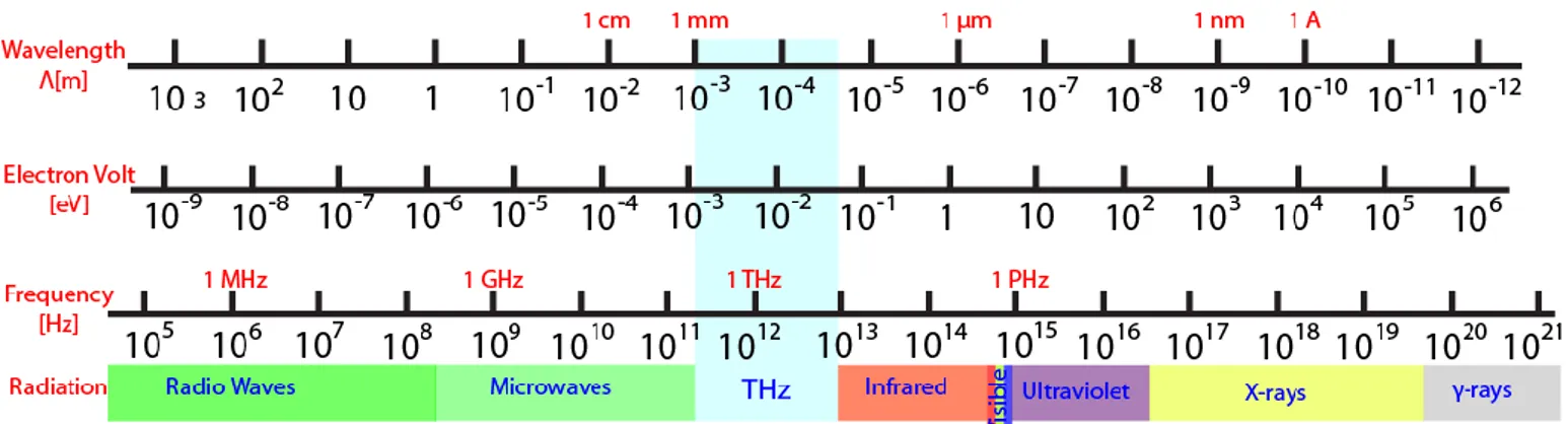
The electromagnetic spectrum between 0.3 – 10 THz is currently referred to as THz radiation, THz waves or T-rays [1], [2]. In this range, the radiation is characterised by a wavelength between 1 and 0.03 mm, a photon energy between 1.24 and 41.4 meV, a Boltzman temperature between 14.4K and 480K, and a wavenumber of 10-334 cm-1, respectively. As a reference, a 1 THz photon has a period of 1 ps, a wavelength of 300 μm, an equivalent Boltzman temperature of 47.6 K, energy of 4.1 meV and wave-number of 33.4 cm-1 [3]. Hystorically, Terahertz (THz) radiation has been referred to as “far infrared” or “sub-mm” waves as the THz frequency range is located between microwaves and optics [4], [5], as illustrated in Figure 1. For decades, the main interest was limied to high-resolution spectroscopy and remote sensing where heterodyne and Fourier transform techniques have allowed astronomers and chemists to measure, catalogue and map thermal emission lines for a wide variety of light-weight molecules. Applications outside those specialised fields was hampered by shortage of emitters and detectors able to produce and detect THz signals with reasonable cost and acceptable performances. This shortage has originated the so-called “THz gap”. Nowadays, innovative THz sources and detectors are becoming available, with improved performances and relatively low cost, allowing to progress in the production of new instrumentations and measurement systems.
2
One of the main advantages of THz wave is that it can penetrate human tissues even if it is not ionizing like X-rays, thus representing an ideal candidate to replace X-rays in diagnostics, the latter with energies in the range 100eV to 100 keV [6]. Another benefit is that materials like paper, plastic, wood, ceramic, clothes are transparent to the wave enabling several novel applications, as will be reported later. However, it cannot pass through metal (it is reflected) and it is highly absorbed by water. This absorption is mainly due to the vibrational-rotational levels of water vapour [7].
Figure 2: Absorption coefficient absorption and attenuation of the atmosphere with five different percentage of relative humidity at 296 ±2 K; adapted from [8].
Figure 2 reports the absorption coefficient of atmosphere with five different rates of relative humidity (RH) at room temperature of 296 ±2 K (23°C), from 15 to 90 RH %, in the range 0.5 to 2.4 THz [8]. As observed in Figure 2, the absorption of the THz radiation increases by increasing the relativity humidity, representing therefore an important parameter to deal with. Moreover, Figure 2 shows a series of “sharp” absorption lines, whose number and width depend, as before, on the humidity percentage. Two spectral windows, with almost 150-200 GHz width, are present below 1 THz and remain usable also at high humidity. One spans over [0.6 and 0.75] THz range, and the other between is 0.8 and 1 THz. Above 1 THz the presence of absorption lines is predominant and there are not practically useful spectral windows for Telecom. However, this part of spectrum is of particularly interest since many molecules have their fingerprint in this region and may be useable at short range. Atmosphere purged with nitrogen represents the most common and easily implemented solution to solve the humidity absorption. An alternative is represented by a vacuum chamber with a rotary vacuum pump.
3
1.2 Terahertz market
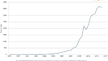
The focus on THz radiation in the last decade is reinforced by various studies on THz papers, patents and market trend [9]–[14]. In order to have a reliable idea of the phenomenon, we performed an analysis on the Scopus database [15] by searching how many papers contain the word “terahertz” as topic ( title, abstract, key word) in the timeframe from 1973 to 2015, data reported in Figure 3. The latter shows an exponential growth of the number of paper started, essentially, around 2000. Only in 2015, more than 3500 papers have been published and this number should increase over the year.
Figure 3: Number of published papers on terahertz paper versus year. Figure from “Scopus”.
Figure 4: Number of published papers on terahertz paper by country. Figure from “Scopus”.
From the same data collection, we extracted information on the country performance on publishing papers dealing THz. At the first position, as expected, we find USA with more than 50% of the papers,
4
followed by China and Japan, the latter is a pioneer in science and technology of the THz range research from the very beginning. Germany ranks forth; indeed, most THz company/distributors have their headquarters there.
Another significant factor explaining the great attention of the scientific community on the THz field can be found on patents analysis, which gives an indication from an industrial and commercial point of view. We collected data, until 2015, from “Lens.org” free patent website [16] by searching the key word “terahertz”, Figure 5 and Figure 6 report the patent versus application years and versus jurisdictions, respectively. From Figure 5 a positive trend of the number of patents year by year is observed, with more than 2000 patent applications in 2015. Concerning the number of patents for country, the same trend of Figure 4 is observed.
Figure 5: Terahertz patents versus years of publications. Figure from “Lens.org”.
Figure 6: Terahertz patents by jurisdictions. Figure from “Lens.org”.
The growing number of patents leads to an increased global THz market as shown in Figure 7 that reports data from a recent TEMATYS report on “Terahertz Components & Systems: Technology and Market trends UPDATE 2016” [10]. The report analyses the global THz market from 2015 and
5
provides a forecast until 2020. In 2015, the market was about 40 M€; it is expected to double to almost 100 M€ in five years, with a 16% compound annual growth rate (CAGR).
Figure 7: THz market size in millions of euro versus year. Figure from TEMATYS report on “Terahertz Components & Systems: Technology and Market trends UPDATE 2016”.
Even if we are not in a blue ocean, the THz frequency range represents a very good perspective for researchers, especially for those willing to transfer research technology into spin-off companies.
1.3 Terahertz applications
The THz frequency range is under intense investigation due to its applications in cross-disciplinary fields, such as secure short-range communications, life-science, cultural heritage, defence, safety and security [17]–[24]. Among these, which is the killer application for enabling a real commercialization of products/setup based on THz wave? In other words, as cited in [25], what THz wave can do cheaper, do more of, or do better than other optical or microwave techniques ? In this section, we briefly introduce some applications of terahertz technology and try to answer this question.
One and well established application of THz radiation in material science is THz time domain spectroscopy (THz-TDS). This is a spectroscopic technique that has the striking advantage of recovering both amplitude and phase of the signal at the same time. This unique feature gives the possibility to extract the complex refractive index of the material and hence its real (refractive index) and imaginary components (from which the absorption coefficient can be extracted) [26]–[28]. The extraction of these parameters is not easy and many researchers work on developing novel and
6
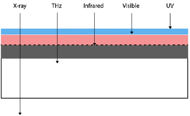
improved algorithms that take into account all the possible problems, such as Fabry-Perot effect, multilayer, liquid and so on [29], [30]. Furthermore, most of materials often utilized in optics, such as glass, some polymer, metal oxides (ITO), are not suitable for THz wave because of their absorption and reflection of the input THz radiation [31], [32]. In the following of this thesis, we will give a review of the most common polymers used in this frequency range. On the other hand, there are some materials that are opaque in the visible range but transparent at THz such us fabrics, cardboard, some plastics, some human tissue and so on. These unique features can be implemented in process control methods of industry, for example automotive, aeronautics, pharmaceutical and so on, especially where non-destructive testing (NDT) are needed [22]–[24], [33]–[48]. However, the implementation in inline production processes is not easy for several reasons such as complex systems and high cost; thus only few applications really can be adopted in industrial processing. For instance, one potential application is paint thickness measurement in multilayer structures (supported by the high skin depth of THz wave) [49]–[51], since the THz technique has the advantage to provide information on a variety of coating films, thickness of each layer in a multilayer, map distribution and so on. Wood products are transparent to THz radiations, and sensitivity to fibre orientations with good resolution is achieved [17], [52]. In the aeronautics industry, THz imaging is employed to examine composite materials, especially to find defects as external material inserts, delamination and so on [53], [54]. In the pharmaceutical industry, THz radiation offers several benefits as individual fingerprint of active pharmaceutical ingredient (API), deep skin depth, non-ionizing energy, identifications of coating thickness and uniformity, tablet density and integrity, pharmaceutical quantifications, polymorphism and so on [55]–[61]. Related to NDT, cultural heritage represents another fascinating field of applications. THz wave possess higher skin depth with respect to IR or visible light (Figure 8), therefore it is possible to retrieve information about underlying layers which possesses unique fingerprint in the THz range [17].
7
This is particularly advantageous in analysis and restoration of paintings non-destructive cross-sectional imaging and more information about the material utilized by the artist can be obtained [48], [62]–[66].
Some materials possess distinctive feature at THz, like a “fingerprint” and this property is used for detect and identify explosive and drug. THz waves can then be applied overall in the security and defence field, as identification of concealed weapons, land mines and so on. Moreover, since THz is health safety, it is possible to use it for scanning people at security check desk [21], [67]–[71]. In this context, we can also include life-science applications especially for bio-sensing and for imaging. In the first case, the unique fingerprint of the molecules is analysed. In the latter case, the research community has put many efforts in order to develop imaging systems that could replace X-ray imaging. The reason lies in the fact that THz radiation is not ionizing, since it excites only vibrational and rotational states, not altering the electronic state of molecules, therefore is safer than X-ray [28], [55], [72]–[78].
There is an increasing demand of high data rate telecom communication, especially for the wireless one. In fact, the exponential growth of the data traffic, especially for internet protocol, is due to the increasing number of the devices able to receive and transmit data. Today, the radio-frequency wireless communication conventionally uses a carrier frequency of maximum 60 GHz with a bandwidth of 7-9 GHz that is almost saturated, therefore the use of higher frequency is necessary to meet the end-user requirements [79], [80]. However, the atmospheric attenuation of THz waves represents a great obstacle. For this reason, the optimistic applications lie in short range communication systems such as, home, office or conference room wireless networks, device-to device communication and so on [19], [81]–[86].
1.4 Terahertz generation and detection
The principal reason that restricted the investigation of the material interaction in THz frequency region, as already said, is due to the technological limitation of source and detector. Regarding the sources, generally, they can be divided in two classes: Time Domain Generation and Frequency Domain Generation. These usually result in broadband and narrowband spectra, respectively. We briefly introduce these two classes, starting from the Time Domain one [3], [87].
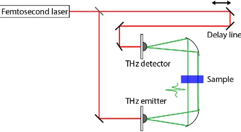
Figure 9 reports a schematic representation of a THz broadband system, where a pulse of a femtosecond laser, usually < 100 fs and λ around 1550 or 800 nm, impinges on a beam splitter and it is divided in two portions, beam1 and beam2. The former is incident on the DC-biased emitter where a current spike is photo-generated, and thus THz pulse is emitted, which is directed towards the
8
sample and then focused on the detector. Meanwhile, the other laser pulse travels through a mechanical delay line and successively focused on the detector. This part of the process is of paramount importance since it allows recording the THz signal as a function of time. The motivation lies in the principle of operation of the THz detector, in fact it can acquire the THz signal only when both the THz pulse and laser pulse in beam2 impinge at the same time on it, being the detected electrical signal proportional to the electric field of the THz pulse. Therefore, as a consequence of changing the time at which beam2 impinges on the detector the time at which the THz pulse is recorded is different. Subsequently, by applying a Fast Fourier Transform (FFT) to the registered signal the amplitude and phase of the THz pulse is obtained. For this kind of system, various sources are available as for example photoconductive antennas (PCA), nonlinear crystals, photo-Dember effect emitters, electron accelerator and so on, where the first two are most used ones. We will give a briefly introduction of some of them.
Figure 9: General scheme for THz time domain system with reflective optics. Equivalent arrangement can be assembled with
refractive/diffractive optics.
In the PCA, the laser radiation activates an optical dipole switch that is part of the whole antenna. Various switch geometries are possible. However, stripe lines having a gap between them, represent the most common ones [88]. Other options are bow-ties, offset dipoles and Hertzian dipoles. The laser pulse is focused on the gap while a DC bias electric field is applied across the gap. When the optical pulse impinges on the gap, it generates photo-excited carriers which are successively accelerated by the bias voltage. The generated transient electrical current produces an ultra-short electromagnetic pulse radiation in the THz range. Regarding the materials utilized for the substrate of the PCA are semiconductors with high mobility but short recombination time such GaAs, LT-GaAs, InGaAs and InP represent the most utilized ones [88]–[91].
As already stated, crystals with nonlinear optical properties represent another common source of THz radiation and ZnTe is the most representative. Other crystals are available as LiNbO3, InP, GaAs,
9
GaP, GaSe, LiTaO3. Moreover, organic polymer and crystal can be used such as APC (amorphous
polycarbonate), DCDHF (dicyanomethyllenedihydrofuran), DAST (4-N,N-dimethylamino-4′-N′-methyl-stilbazolium tosylate) and MBANP (-)2-(α-methylbenzylamino)-5-nitropyridine [3]. In a non-linear optical medium, the polarization induced in the medium is related to the incoming electric field and is described by a series of power terms of increasing order. In this context, only the second-order terms are considered. When an optical radiation impinges on a nonlinear crystal, its electric field components induces a nonlinear polarization response that depends on the angle between the incoming radiation and the crystal axes. We refer to optical rectification when a constant optical electric field produces a static polarization. However, for generating THz radiation a pulsed optical radiation is used, therefore the induced polarization is time dependent and is proportional to the envelope of the optical pulse. This dependence of the polarization is responsible of the THz signal [3], [92], [93].
A typical TDS spectrum of THz radiation generated by PCA is reported in Figure 10, on the left in time domain while on the right in frequency domain achieved after a Fast Fourier Transform (FFT). It is possible to notice in Figure 10, right side, that the spectra have a peak at low frequency that decreases by increasing the frequency, reaching the noise level.
Figure 10: Typical Terahertz spectrum in time domain (left) and frequency domain (right).
Concerning the electron accelerator method, we briefly present the way to use a synchrotron for generating THz broadband radiation. An ultrashort laser pulse impinges on a GaAs surface generating ultrashort electrons clusters, successively accelerated to relativistic speed. These electrons produce THz radiation when they are steered using magnetic field, namely the Bremstralung effect[94].
10
After Time Domain generation, we introduce now some of the sources available for Frequency Domain generation, also known usually as Continuous Wave (CW) generation. Noticeable, examples are Photomixing, Quantum Cascade Laser (QCL), Free Electron Laser (FEL), Microwave Frequency Multipliers, and so on.
A photo-mixer represents the alter ego of PCA in the contest of Frequency Domain generation. Figure 11 illustrates a scheme of this class of system where two optical CW lasers with two adjacent different frequencies, ω1 and ω2 respectively, are focused on a phot-mixer interfering each other and generating
a beat signal at the frequency difference ω = ω1 – ω2. The photo-generated current oscillates at the
frequency ω that impinges on an antenna integrated in the photo-mixer producing a THz wave. The latter can be modulated by tuning the frequency of one laser. The photo-mixer is the core of the system and it is composed of a metal-semiconductor-metal structure, where one between GaAs, LT-GaAs and InLT-GaAs constitutes the semiconductor layer. As in the case of PCA, various antenna designs, such log-spiral, dipole antenna and bow-tie, have been utilised [17], [90], [95], [96].
Figure 11: Example of THz Frequency Domain system representing a Photomixing setup scheme with reflective optics. Equivalent
arrangement can be assembled with refractive/diffractive optics.
Quantum cascade lasers (QCL), first demonstrated in 1994 [97], have the potential to become the most common THz source if they could be made cheap, powerful and operating at room temperature [98]–[101]. Much effort is been spent by the research community to increase the operating temperature, however the highest reached is around 225K [102]; at the moment this denotes the major drawback hampering the potential of this technology; though some novel approach are being pursued to raise the temperature [103]. In a QCL, laser emission results from inter-sub-band transition of electrons in semiconductor heterostructure quantum wells. The latter is made up of repetition periods of wells and barriers where each period is separated by an injection region. The general concept is to force the electron to emit photons inside the well in a transition from the upper energy level to the lower one. Once the photon is emitted the electron, through the injection region, is injected in the upper energy level of the following well and the same process occurs. Thus, one electron produces
11
many photons. This is in contrast to what usually happens in a common semiconductor laser where an electron-hole pair emits only one photon. The thickness of the quantum well and barriers determines the photon energy and therefore the emitted wavelength without the need to change the materials stoichiometry of the active region.
The other THz source that we briefly discuss here is the expensive free electron laser (FEL). In this case, free electrons, with relativistic speed, travel inside a laser cavity where a sinusoidal magnetic field is present. This field induces a sinusoidal motion of the electrons releasing monochromatic photons at THz frequency [104].
Frequency multipliers are based on Schottky diodes acting as the equivalent of nonlinear crystals. In fact, utilizing the reactive and resistive non-linearity of the diode, they generate an output wave having a frequency that is the multiple of the incoming one. Their use in the THz region is due to the fact that microwave source at around 100 GHz are easily available [105].
After the discussion on various THz source we briefly introduce some THz detector , such PCA, nonlinear crystal, heterodyne detection, bolometer; however others detector configurations are available [106].
PCA and nonlinear crystals can be employed for detecting THz radiation in a similar manner as discussed above concerning the generation. In the first case, the THz pulse accelerates the photo-excited carriers generated in the detector by the optical beam2. The generated current is converted to voltage that is detected usually with a lock-in amplifier. As for the generation case, the delay line permits to map the THz signal over time. Also in the second case, i.e. nonlinear crystal, the concept is similar to the generating one above described. Stickily speaking, in this situation the THz signal impinging on the detector induces a proportional change in the polarization of the optical pulse. This variation is analysed through a photo-diode obtaining a THz signal [107], [108].
In the heterodyne detection process a mixer, typically a Schottky diode, allows the beating of a reference signal (known as local oscillator) with the unknown incoming radiation generating signals at the sum frequency and difference frequency of the original frequencies. The sum frequency is absorbed (at least to some extent), while the signal with the difference frequency is detected. Thus, the amplitude of the detected signal is proportional to the amplitude of the incoming radiation [109]. This is the optical extension of the heterodyne detection long used for radio signal, where the sum frequency is filtered out by parasitic reactance.
The bolometer is one of the possible thermal detectors utilized in the THz frequency range. The main part of the bolometer is an broadband absorbing element typically made of metal or semiconductor (Si, Ge). The incoming radiation produces an increase of the temperature causing a variation of the electrical resistance of the active element. The detection is based on measuring this variation [110].
12
To sum up there is no a unique choice for implementing THz systems, each source and detector possesses benefits and disadvantages that have to be evaluated depending on the user requirements. For instance, time domain systems show a broadband THz signal, very fast acquisition time but low spectral resolution; it is usually used for materials spectroscopy or thickness measurement. Applications that require high spectral resolution employ frequency domain systems even if the time speed is lower with respect to the time domain one.
1.5 Materials with low loss in the terahertz range
As mentioned in the previous paragraph, the absorption of materials represents one important parameter to be considered when dealing with THz devices. Therefore, it is of paramount importance to find a low loss material suitable as a substrate in the THz frequency range for passive components and components incorporating some type of dynamic modulation as liquid crystal [111], [112], graphene [113]–[115], and so on. For this reason, a literature survey was conducted and the results are illustrated in Figure 12 and Figure 13, which report the absorption coefficient of several materials in the range between 0.3-2 THz, data collected from [4], [26]–[28], [83], [116]–[123].
0 10 20 30 40 50 60 70 80 0.4 0.6 0.8 1 1.2 1.4 1.6 1.8 2 PDMS PET-Mylar PMMA ABS A b s or p ti on C o e ff ic ie n t [c m -1] Frequency [THz]
Figure 12: Terahertz absorption coefficient of Polydimethylsiloxane (PDMS), Polyethylene terephthalate (PET), Poly(methyl methacrylate) (PMMA) and Acrylonitrile butadiene styrene (ABS). Reprocessed from data extracted from [4], [26]–[28], [83], [116]–
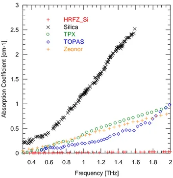
13 0 0.5 1 1.5 2 2.5 3 0.4 0.6 0.8 1 1.2 1.4 1.6 1.8 2 HRFZ_Si Silica TPX TOPAS Zeonor A bs or pt ion C o e ff ic ien t [c m -1 ] Frequency [THz]
Figure 13 Terahertz absorption coefficient of High Resistivity Floating Zone Silicon (HRFZ_Si), amorphous Silica, TPX, Topas and Zeonor®. Reprocessed from data extracted from [4], [26]–[28], [83], [116]–[123].
In particular, Figure 12 reports the data for Polydimethylsiloxane (PDMS), Polyethylene terephthalate (PET), Poly(methyl methacrylate) (PMMA) and Acrylonitrile butadiene styrene (ABS), while Figure 13 for High-Resistivity Floating Zone Silicon (HRFZ-Si), Silica, Polymethylpentene (TPX), Cyclic olefin copolymer (TOPAS) and Cyclo-olefin polymer (Zeonor). Among these, HRFZ Silicon presents the lowest absorption coefficient followed by three polymers, TOPAS, TPX and Zeonor. For all these four materials, the attenuation at 1 THz stays below 0.5 dB/mm. Unfortunately, the exact composition and molecular weight of these low loss polymers are trade secrets and is not possible to retrieve a general understanding of the causes of the different absorption coefficient. However, other parameters like cost, compatibility with fabrication processes, water absorption and so on are also relevant for an accurate decision. Regarding the cost, HRFZ Silicon is the most expensive ones, typically more than €100 for a 2’’ wafer. The polymers, are less expensive and are pellets sold typically for less than 100€/Kg. Among the TPX, TOPAS and Zeonor, following a market survey we found that the latter is the cheaper one and it is available, also, in plate of various millimetre or in thin film. In the latter cases, the substrate is ready to be used. Moreover, its water absorption is nearly as low as that of simple glass. Finally, they are compatible with all solvents and temperature changes involved in the fabrication processes for photolithography and wet-etching of metals [124]. Hence, we focused our attention on Zeonor produced by Zeon Co. The latter is a cyclo-olefin polymer (COP) with excellent combination of optical and electronic properties enabling its use in various application fields such as lighting, automotive, electronics, bioscience, packaging and so on [124]. Its synthesis is illustrated in Figure 14 [125].
14
Figure 14: Synthesis of COP from [125].
We were kindly provided by Zeon Co. with thin foils having thickness of 40, 100 and 188 μm and 2-mm thick Zeonor plate. The latter was characterized by means of THz time-domain spectroscopy (THz-TDS) in transmission mode with a collimated beam in the range 0.3-2 THz by using the available Menlo System TERA K15 [89], an all fiber-coupled spectrometer. In order to prevent absorption of THz radiation by water vapour, the measurements have been conducted in an atmosphere purged with nitrogen (N2). The power transmittance of the sample is normalized to the
one in absence of the sample. Then, by using the software provided with the spectrometer and by applying Fast Fourier Transform (FFT) to the normalized signal, it is possible to retrieve the material properties, namely the refractive index and the absorption coefficient.
1.5 1.51 1.52 1.53 1.54 1.55 0 0.5 1 1.5 2 2.5 3 0.4 0.6 0.8 1 1.2 1.4 1.6 1.8 2 Refractive Index Absorption Coefficient [cm-1] Ref ra c tive Ind ex A b s o rp tio n Coe ffici e n t [ c m -1] Frequency [THz]
Figure 15: Material properties of a 2-mm thick Zeonor® plate characterized by means of THz time-domain spectroscopy.
The extracted refractive index is equal to 1.525 with minor dispersion in the spectral range under investigation while the absorption coefficient increases almost linearly from 0 to 1.3 cm-1 in the 0.3 to 2 THz range. This corresponds to an almost constant imaginary part of the refractive index of approximately 10-3 and a loss tangent of approximately 1.3•10-3. Given their very low absorption, it has not been possible to characterize 100 μm thick Zeonor® foils individually because the difference
15
between the reference signal and the sample measurement were comparable to the noise level of the THz signal. As such, a stack of ten of these foils was assembled and measured as well. The material parameters are fully consistent with the accuracy in estimating the foils and slab thicknesses.
To sum up, for the above-mentioned reasons, Zeonor® thin films have been chosen as substrates for in all cases reported in this dissertation.
1.6 Conclusion
In this chapter, we have reported an overview on the terahertz frequency range that, as already mentioned, lays between the microwave and infrared optics ranges. Therefore, THz sources and detectors are developed by levering techniques from both sides of the electromagnetic spectrum, as illustrated above.
Moreover, we described applications of THz frequency range in several fields, such as life-science, materials science, telecommunication, cultural heritage and more. Furthermore, from the conducted analysis on the THz market, it is realised that the growing interest of scientists is associated with an increasing THz market size. However, this research field is relatively new and although quite some efforts have been devoted to the development of sources and detectors with improved performance and relatively more affordable cost, much work remains to be done. At the same time, the development of THz components with functionality equivalent to those easily available in optics, but at an affordable cost, such as polarizer, polarizing beam splitter, beam splitters, filters, phase shifters, absorbers, lenses, diffractive optics, and so on. Hence, during my research activity, the main focus was the realization of a new class of flexible and conformal THz devices both static and with dynamic control. We developed a flexible wire gird polarized, two novel classes of bandpass filtering elements, bandstop filter and, in conclusion, tuneable bandpass filters are much required to fully exploit the potential of THz waves. Hence, we performed a detailed analysis in order to find the best substrate choosing in the end the cyclo-olefin polymer Zeonor, as reported above. Then, by means of finite-element method (FEM) implemented in commercial solver several designs were analyzed, among these the ones with the best performance were selected for the fabrication. The latter was mainly performed using standard UV-photolithography. Successively, the fabricated components were characterized using terahertz time domain spectroscopy system.
16
Chapter 2:
Flexible terahertz wire grid polarizers
© Opt Letters 41, 2009 [2016] Optical Society of America.]
Part of the work herein reported is reprinted/adapted, with permission, from [ A. Ferraro, D.C. Zografopoulos, D. C., M. Missori, M. Peccianti, R. Caputo, and R. Beccherelli, R.: ‘Flexible terahertz wire grid polarizer with high extinction ratio and low loss’, Optics Letters, 2016]
and © [2017]
Part of the work herein reported is reprinted/adapted, with permission, from [ A. Ferraro, D.C. Zografopoulos, R. Caputo, and R. Beccherelli, R.: ‘Terahertz polarizing component on cyclo-olefin polymer, submitted, 2017]
2.1 Introduction
A particular feature that characterises THz sources such as quantum cascade lasers [100], [101], diode based frequency multiplier [90], [105], vacuum tubes (BWO, Gyratron, FEL etc ) [3], [87] is that their output radiation is polarized to some extent. Terahertz time domain spectroscopy (TDS) setups often employ a low conductivity GaAs antenna, which radiates a field intrinsically polarized along the axis of the antenna. Hence, there is often a necessity to process, control and analyse the state of polarization of the THz beam. While in optics, prism polarizers offer 50-60 dB extinction ratio and low insertion losses and iodine loaded stretched polymer offers 30-40 dB at a negligible cost, no equivalent devices exist at THz mainly due to material absorption. Various THz polarizers have been so far developed using different approaches, for instance, based on aligned carbon nanotubes [126], nematic liquid crystals [127], tunable metamaterials [128], thin-film metallic grating [129], [130] or spoof surface plasmon polaritons [131]. Among these, the majority is based on some configurations of metallic wire grids, which may be either free-standing or deposited on a dielectric substrate. In most respects, a wire grid polarizer (WGP) with a deep sub-wavelength pitch can be thought of as the
17
simplest metamaterial device with sub-wavelength features, whose anisotropic performance stems from the polarization-dependent properties of the effective medium composed by the metallic grid and the surrounding isotropic dielectric. Free-standing THz WGPs that are already commercially available offer high transmittance [132], [133]. However, they are expensive and mechanically fragile. Conversely, wire-grids patterned on a dielectric substrate are less expensive and easier to produce, because they can be fabricated using standard photolithography, as well as various large-area techniques. In [134] an extinction ratio (ER) of 35 dB at 0.5 THz is achieved, but the transmittance of the polarizer is approximately 50% owing to the high reflectivity of the Si substrate. In [135], Pickwell-MacPherson’s group achieved an ER between 20 and 49 dB in the 0.2-2 THz range and an insertion loss (IL) lower than 1 dB. Nevertheless, the employed fabrication process relies on dry bulk micromachining of a silicon wafer. As such, it requires a significant amount of process consumables. Although a wet-etch process may reduce the cost, the silicon based process is intrinsically constrained by the size of crystalline wafer. A technique to improve the ER performance of the WGP is to fabricate a bilayer [136], or multilayer structure [137]. In both cases two or more single WGPs are stacked together, thus increasing the number of fabrication steps and hence the overall complexity and cost. Takano et al [138] have fabricated a WGP on a flexible substrate with 140 nm pitch by means of nano-imprinting but the device shows significant losses.
In our case, we experimentally demonstrated an Al-based THz WGPs with very low IL and high ER [139], [140] fabricated on a cyclo-olefin polymer substrate (Zeonor®) having very low loss and a high mechanical flexibility. A systematic numerical parametric study was initially performed, by varying the substrate thickness, the wire grid period and fill factor, in order to identify the structures with a favourable trade-off between insertion losses and achievable extinction ratio. Subsequently, WGPs were fabricated on both 40 and 100 µm thick Zeonor® foils. Although standard photolithography techniques have been used for this proof of concept, the polarizers can be fabricated with large metal coaters and/or roll to roll patterning techniques [141], [142] over large area at a negligible cost. Most importantly, the possibility to bend and conform the fabricated WGP over a rigid surface can open the route for new kinds of integrated and flexible THz devices.
2.2 Design
The investigated polarizer layout is reported in Figure 16 where its geometrical parameters p, w and d respectively represent the pitch of the metallic stripe grating, the width of the metal stripe and substrate thickness. Figure 16 illustrates the operational principle of a wire grid polarizer (WGP), where the field components of an unpolarised incident wave impinging on it experience a different
18
behavior. In particular, the polarization component perpendicular to the metal stripes (E⊥) is
transmitted, while the one parallel to the metal stripes (E‖), that is back reflected, represents the
unwanted polarization component.
Figure 16: Schematic layout and definition of the geometrical parameters of the investigated polarizer. The Al thickness is 200 nm.
The performances of the polarizer are defined by its ER and IL, expressed as
ER = 10 log10(T⊥ ∕ T‖) (1)
and
IL = −10 log10(T⊥ ∕ TN2 ); (2)
where T⊥ and T‖ are the transmitted power coefficients for the field components respectively
perpendicular and parallel to the metallic stripes, while TN2 is the power transmitted in absence of the
polarizer.
A systematic numerical study was conducted in order to find the best performance of the WGP in terms of ER and IL by means of the finite-element method (FEM) implemented by means of the commercial solver COMSOL Multiphysics©. Aluminium was modelled as a Drude medium, with plasma frequency ωp= 2.243x10¹⁶ rad/s, and electron decay rate γ=1.243x10¹⁴ rad/s. The incoming
THz wave impinges perpendicularly (at normal incidence) on the WGP and the transmission coefficients are calculated for the Ex and Ey components of the electric field (Figure 16) which
respectively represent the reflected and transmitted component.
The performances of the WGP depend on its geometrical parameters, namely its pitch (p) and the width of the metallic stripes (w). From those parameters, the fill factor (F) is derived, defined as the ratio between the stripe width and the pitch of the one-dimensional periodic lattice (F=w/p). Furthermore, also the Zeonor® substrate film thickness (d) has a relevant effect on the properties of the polarizer, as reported in this paragraph. Both the period and the fill factor influence the polarizer
19
extinction ratio; when the period increases, the extinction ratio decreases, while the opposite happens by increasing the fill factor. On the contrary, the insertion losses decrease while decreasing period and/or fill factor values.
0 20 40 60 80 100 0 2 4 6 8 10 0.5 1 1.5 2 2.5 10 µm 20 µm 50 µm 10 µm 20 µm 50 µm P o w e r E xt in c ti o n R a tio [ d B ] P o w e r I n s e rtio n L o s s [d B ] Frequency [THz]
Figure 17: Numerical investigation of the WGP extinction ratio and insertion losses for pitch fill factor F=70% as a function of the pitch on a 100 µm thick foil for normal incidence.
0 20 40 60 80 100 0 1 2 3 4 5 6 7 0.5 1 1.5 2 2.5 30 % 50 % 70 % 90 % 30 % 50 % 70 % 90 % P o w e r E xt in c ti o n R a tio [ d B ] P o w e r I n s e rtio n L o s s [d B ] Frequency [THz]
Figure 18: Numerical investigation of the WGP extinction ratio and insertion losses for pitch p=10 μm on a 100 µm thick foil as a function of fill factor for normal incidence.
Herein, we fixed the Zeonor® thickness equal to 100 μm, as physical foils were available. The first parameter that has been taken into account is the pitch of the grating structure, therefore we fixed the fill factor to 70% and varied the pitch to 10, 20 and 50 μm; the calculated power ER and IL are
20
illustrated in Figure 17. The polarizer with 10 μm pitch shows the highest ER, with an extremely high value of 50 dB at 0.3 THz and a minimum of 32 dB at 2.5 THz. As expected, the ER for p=20 μm decreases roughly by 6-7 dB while for p=50 μm the situation gets worse, with an observed reduction of the ER in excess of 15 dB. Regarding the IL, the Zeonor® film thickness influences this property causing Fabry-Perót (FP) effect, further details are reported later. In fact, for p=10 μm the IL are principally due to this effect remaining below 1 dB in the whole frequency range under investigation. At around 1 THz and 2 THz, the impedance matching condition enables a total transmission of the incoming polarization component. The 20 μm period case shows a similar trend with a slightly higher IL, owing to increased reflection of E due to the metal. For p=50 μm, larger IL values are found, with a maximum of 4 dB. To sum up, the best performances were reached with a period of 10 μm, which represents in this case the smallest one under study.
Once we found the period, we studied the effect of the fill factor. Figure 18 reports the numerical investigation of the ER and IL of the proposed WGP where the pitch has been fixed to 10 μm and F varies from 30% to 90 %. Regarding the ER, its value increases by increasing the fill factor, as expected, because the increasing metal percentage reflects a greater amount of the unwanted polarization component (Ex). At 1 THz, ER is equal to 30 dB for F=30%, while it becomes 70 dB for
F=90% representing the maximum value. However, the IL are negatively affected by a large F as more extended metallic parts in the structure also increase reflection losses for T. In fact, we can observe in Figure 18 that for F=90% the losses are between 1 and 2 dB outside the impedance matching condition frequencies.
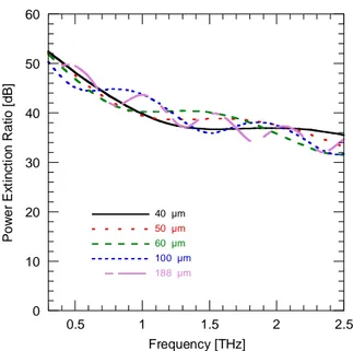
0 10 20 30 40 50 60 0.5 1 1.5 2 2.5 40 µm 50 µm 60 µm 100 µm 188 µm P o w e r E xt in c ti o n R a tio [ d B ] Frequency [THz]
Figure 19: Numerical investigation of the WGP extinction ratio for pitch p=10 μm, F= 70% as a function of Zeonor® film thickness for normal incidence.
21 0 0.5 1 1.5 2 2.5 3 0.5 1 1.5 2 2.5 40 µm 50 µm 60 µm 100 µm 188 µm P o w e r In s e rt io n L o s s [ d B ] Frequency [THz]
Figure 20: Numerical investigation of the WGP insertion losses for pitch p=10 μm, F= 70% as a function of Zeonor® film thickness for normal incidence.
Since the Zeonor® thickness influences the frequency at which the impedance condition occurs, we performed a detailed numerical analysis by varying the Zeonor® thickness and fixing the period and the fill factor. We chose the thickness values that are commercially available from Zeon Co., namely 40, 50, 60, 100 and 188 μm [31]. Figure 19 and Figure 20 report the numerical results of the extinction ratio and insertion losses, respectively, for a polarizer having pitch p=10 μm, F= 70% as a function of the Zeonor® film thickness at normal incidence. As already mentioned, the Fabry-Perot effect depends on the substrate thickness, the oscillating period of the ER and IL increases as the thickness gets higher, as observed in both Figure 19 and Figure 20. This phenomenon is of fundamental importance especially for the insertion losses since it is possible to tune the frequency at which IL=0 by only varying the substrate thickness.
In conclusion, we found a satisfactory trade-off between high extinction ratio, low loss and low fabrication cost with the following geometrical parameters: Zeonor® thickness = 100 μm, grating pitch p=10 μm, F=70% and Aluminium thickness= 200nm. However, in order to facilitate the fabrication on the 40- μm thick Zeonor®, we doubled the period keeping the same fill factor resulting in a slightly reduction of the performances.
2.3 Fabrication process
Now, we briefly introduce the photolithography procedures involved during the fabrication of our devices in clean room. Figure 16 describes the fabrication flow in which the fundamental elements
22
are a light source, a photomask (master) a photosensitive material (photoresist) and a developing solution.
The first step requires a foil of Zeonor® film, 1 inch size, cut with scissors and cleaned with acetone and isopropanol (IPA) in an ultrasonic tub. Then the slab is put under high vacuum and a layer of metal is thermally evaporated on it The skin depth (δ) in aluminium is 150 nm at 0.3 THz and 52 nm at 2.5 THz. Hence, we set its thickness at 200 nm thick. Later on, a positive photoresist (S1813 from Shipley) was spin-coated at 3000 rpm for 30 seconds and then backed at 115°C for 2 minutes, resulting in a uniform layer having a final thickness of 1.3±0.1 μm. The photoresist top surface is exposed to the UV light pattern (=365 nm and I=60 mW/cm2) produced by a using a Karl Suss
MA150 mask aligner exploiting a photomask with the desired geometry. Through the photomask, only specific areas of the resist layer are illuminated with UV light. In case of a positive photoresist, UV light induces a change in the properties of the material which becomes soluble for a suitable developing solution. On this way, after the exposure, the sample is immersed in the developer MF319 for 50 seconds, rinsed with deionized water (DI H2O) and dried with nitrogen. Afterwards, a hard
bake of the sample at 120°C for 5 minutes increases the photoresist resistance to wet chemical etching solution. Once the desired pattern is transferred on the sample surface, the exposed aluminium (area not protected by the resist) is wet-etched in a solution of H3PO4∶H2O∶CH3COOH∶HNO3=16∶2∶1∶1.
Finally, the sample is clean with acetone and IPA and dried with nitrogen flow in order to remove the residual photoresist.
23
2.4 Experimental results
After the design optimization process, a polarizer with a pitch of 10 μm and fill factor of 68% was fabricated on low loss flexible and conformal 100 μm-thick Zeonor® foils sized 2.54 cm x 2.54 cm (1 inch x 1 inch), using the technique described above. However, all fabrication steps are easily scalable to larger area as well as to a roll-to-roll process. Figure 22 illustrates the fabricated polarizer mounted on a 3D printed curved mount positioned on a manual rotation stage. The insert shows a micrograph of the fabricated WGP taken under optical microscope in transmission mode with a diffraction limited 100x /90 microscope objective, where the black parts are the Al stripes, while the transparent Zeonor® foil appears white. The width is 6.8 μm while the pitch of the structure is 10.0 μm. The deviation of 0.2 µm from the nominal value is within λ/2 of the g-line used to impress the photoresist as expected. Its electromagnetic properties were investigated by means of THz time domain spectroscopy using a Menlo Systems TERA K15 all fiber-coupled spectrometer in transmission mode. The measurements were done in an atmosphere purged with nitrogen (N2) in
order to prevent water absorption of THz radiation. As shown in Figure 18, the ER is expected to reach 70 dB for F=90%. However, the frequency dependant dynamic range of the available TDS Menlo K15, limits the ER that can be reliably measured to the case of F=70% and pitch of 10 µm.
Figure 22: Flexible THz polarizer on a curved mount, placed on a rotation stage for the THz-TDS experimental setup. The insert shows a micrograph of the fabricated WGP (p=10 μm and w=6.8 μm) in X configuration under optical microscope in transmission mode. The black parts are the Al stripes, while the transparent foil appear white.
The emitted THz wave has a diameter of 25 mm, it is collimated and partially polarised with horizontal polarization. Ideally, the accurate measurement of the polarization properties would require a calibration standard with known polarizing properties and preferably, infinite extinction ratio and nil insertion loss. Unfortunately, these conditions are not fulfilled at THz, moreover the emitting and detecting antennas are polarized to some extent, but the manufacturer does not declare their properties. Hence, we have used two identical polarizers in order to perform a self-referenced
24
measurement. The measurement procedure is quite complicated and requires some care since the source and the detector are partially polarized. The first polarizer has been set with its easy axis, namely, the axis that defines the component of the THz wave that is easily transmitted, at 45° with respect to the polarization of the main component of the THz emitted beam. The second polarizer has been set perpendicular to the first one and T|| is measured. Then, the second WGP has been rotated
by 90°, until the maximum detected signal is observed, and T⊥ is recorded. In order to measure the
IL, we have referenced the transmitted radiation when both the first and the second WGP are into the maximum transmission, i.e., with the metal wires perpendicular to the emitted polarization, and thus parallel to each other. Subsequently, the second WGP was removed and the ILs were calculated as the ratio between the maximum detected power in the presence of the second WGP and the one measured without it [139], [143].
Since the fabricated WGP has a fill factor of 68%, we have performed a new numerical analysis for a better comparison between numerical and experimental results. The performance of the polarizer was first investigated in a flat configuration. Then, given that the WGP is fabricated on a flexible and conformal substrate, we have performed the measurement also in two different bending configurations using a custom made 3D printed curved mount with a radius of curvature R=12.5 mm.
0 10 20 30 40 50 60 0.5 1 1.5 2 2.5 Theoretical Flat Flat X-curved Y-curved P o w e r E xt in c ti o n r a ti o [ d B ] Frequency [THz]
Figure 23: Comparison of experimental measurements and numerical results of the extinction ratio for the THz WGP with p=10 μm and F= 68% for normal incidence. The scattering of data at higher frequencies is due to the decreasing signal-to-noise ratio of the instrument.
We define the configuration with the bend along the Al stripes as X-curved, while the one curved perpendicular to the stripes as Y-curved.Figure 23 reports the comparison between theoretical flat configuration (black line), experimental flat (light-blue line), X-curved (green line), and Y-curved
25
(orange line) configuration of the power extinction ratio (ER), see Figure 22 for the axes. The ER for the flat case agrees very well with the simulation results showing an ER larger above than 30 dB for the entire range and between 35 dB and 45 dB for 0.3 – 1.5 THz. The results in curved configuration, even if the WGP is significantly distorted, are similar to the flat case showing an ER above the target value of 30 dB and values up to 50 dB at the low-frequency edge of the spectrum under study. These results confirm the extraordinary performance in terms of ER for the proposed polarizer in all the cases under study. Those values are equivalent to the state of the art polymer polarizers in the visible range. Moreover, Figure 24 reports the same comparison between theory and experimental measurements for both the flat and curved configurations in terms of insertion losses (IL). As in the case of the extinction ratio, the insertion losses for the flat and Y-curved cases agree very well with simulation, with a value below 1 dB for the entire range in consideration. In both cases, the losses are almost exclusively due to Fabry-Perót effect in the polymer, with almost no losses at approximately 1 THz and 2 THz. Instead, in the X-curve case the insertion losses are slightly affected, which is attributed to the change of the effective angle of incidence across the surface of the polarizer owing to the curvature. 0 0.5 1 1.5 2 2.5 3 0.5 1 1.5 2 2.5 Theoretical Flat Flat X-curved Y-curved In s e rt io n L o ss [ d B ] Frequency [THz]
Figure 24: Comparison of experimental measurements and numerical results of the insertion losses for the THz WGP with p=10 μm and F= 68% for normal incidence. The scattering of data at higher frequencies is due to the decreasing signal-to-noise ratio of the instrument.
Successively, a WGP with a pitch 20 μm and fill factor of 70% (w =14 μm) was fabricated on 40 μm-thick Zeonor® foils, illustrated in Figure 25. The latter shows the WGP fixed on a standard 1” rotation mount while the inset reports a micrograph taken under optical microscope in transmission
26
mode with a diffraction limited 100x /90 microscope objective, where the black parts are the Al stripes, while the transparent parts are Zeonor®, as in Figure 22.
Figure 25: Terahertz polarizer on a standard 1-inch mount. The inset reports a micrograph taken under the microscope in transmission mode of a fabricated sample with p = 20 μm, w = 14 μm on a Zeonor® foil with d = 40 μm.
Figure 26: Comparison of experimental measurements (markers) and numerical (solid lines) results of the extinction ratio for THz WGPs with p=20 μm and F= 70% on Zeonor® foil 40 and 100 μm thick.
Figure 27: Comparison of experimental measurements (markers) and numerical (solid lines) results of the insertion loss for THz WGPs with p=20 μm and F= 70% on Zeonor® foil 40 and 100 μm thick.
27
In order to clearly demonstrate the effect of the substrate thickness on the performances of the polarizer, another WGP with the same geometrical features was fabricated on Zeonor® having thickness of 100 μm. Figure 26 shows the comparison of numerical (solid lines) and experimental (markers) results of the power ER for the proposed WGPs on 40 and 100- μm thick Zeonor® substrates having p=20 μm and F= 70%. For both WGPs, the experimental measurement are in very good accordance with the simulations ones exhibiting an ER of 45 dB at 0.3 THz which decreases as the frequency increases until the value of 30 dB at 2.1 THz. It is remarked that the slope of the ER depends on the polymer thickness, in particular for the WGP fabricated on 40 μm Zeonor® the slope is more regular respect to the 100 μm one due to the Fabry-Pérot effects. The influence of the polymer substrate on the polarizer performance is more evident in Figure 27, which reports the IL for both samples. In both cases the IL is as low as 0 dB at the matching frequency and never exceeds 1.1 dB. It is remarked that, owing to matching condition, the WGP on 40 μm thick Zeonor® shows an IL of 0.18 dB at around 2 THz which is important for use in combination with THz QCL sources because back-reflections are to be avoided [23]. Moreover, this feature is not easy to obtain because most common polymers used at THz exhibit a great attenuation a 2 THz. Regarding the sample on 100 μm Zeonor®, the IL approaches 0 dB at 0.9 and 1.7 THz, confirming the trend observed for the other class of WGP that has p=10 μm.
It is worth nothing that the matching frequency of the two devices does not simply scale with the thickness of the polymer foil. We here stress that the matching frequency is shifted to lower frequency for a larger fill factor and for a larger pitch.
2.5 Conclusion
To sum up, a low-cost Al THz WGPs were fabricated on flexible and conformal low-loss dielectric foils of Zeonor® having thickness of 40 and 100 μm. The geometrical parameters were optimized for the 100 μm case by a detailed study using the finite-element method (FEM). The final design of the proposed polarizer has a pitch of 10 μm and fill factor of 68%. Its performance in bending configurations shows little difference with respect to the properties of the flat sample, namely an extremely high ER with max of 45 dB in the 0.3-1 THz range and of 30 dB up to 2.5. Furthermore, it shows an IL less than 1 dB for the entire frequency range, and at targeted frequency the IL is almost zero. Regarding the WGP on a 40 μm thick substrate, even if we doubled the pitch for facilitating its fabrication, it is only slightly less performant respect to the optimized one showing similar value of ER and IL. Thanks to its IL behaviour it can be used with quantum cascade lasers operating at higher frequency. For all the fabricated samples, the experimental results are in excellent agreement with the
28
theoretical study. The outstanding properties of the polarizer pave the way for a new class of flexible and conformal THz devices. Moreover, the proposed polarizer can be fabricated with low-cost techniques used for large-area electronics such as roll-to-roll or gravure printing.
![Figure 2: Absorption coefficient absorption and attenuation of the atmosphere with five different percentage of relative humidity at 296 ±2 K; adapted from [8]](https://thumb-eu.123doks.com/thumbv2/123dokorg/2871806.9469/12.892.166.732.306.658/absorption-coefficient-absorption-attenuation-atmosphere-different-percentage-relative.webp)

![Figure 14: Synthesis of COP from [125].](https://thumb-eu.123doks.com/thumbv2/123dokorg/2871806.9469/24.892.95.804.121.250/figure-synthesis-of-cop-from.webp)