Faculty of Pharmacy, Nutritional Sciences and Health Care Department of Pharmaceutical Sciences
"8. Telesio-Doctoral School of Science and Technique" Mesophases and Molecular Materials
CHIM/02
XXIV cvcle. PhD thesis
Behavior and effects of arlditives
in liquid crystal compounds
g,rPlWr*
\t
cu_19_'guf
__ )
Supervisor 6h.NICOLE
Marco VIVACQUA Prof. Cmlo VERSACE
f',A /*'*
I Mh l'-/ r /\{ ,{aq,.<zI
I School Director
Author’s e-mail: [email protected] [email protected]
Author’s address: Department of Pharmaceutical Sciences University of Calabria Via Pietro Bucci, Ed. Polifunzionale 87036 Arcavacata di Rende, Cosenza
ph.: +39 0984 493266 ph.: +39 0984 466478 cell: +39 349 3253095
I, Marco Vivacqua, hereby confirm that the work submitted in this report is my own and that I have not violated the University of Calabria's policy on plagiarism.
Table of contents
Preface ... 1 General Introduction, Aims and Organization of this Thesis ... 1 1 General Introduction ... 1 2 Aims of this thesis ... 3 3 Organization of this thesis ... 3 Chapter 1‐ Liquid Crystal ... 5 1.1 Liquid Crystals ... 5 1.1.1 Introduction ... 5 1.1.2 Chemical properties of liquid crystals ... 10 1.1.3 Phases of Liquid Crystal ... 13 1.1.3.1 Nematic Phase ... 13 1.1.3.2 Cholesteric Phase ... 14 1.1.3.3 Smectic Phase ... 15 1.1.3.4 Columnar Phase ... 17 1.1.4 Birefringence in Liquid Crystals ... 17 1.1.5 External Influences on Liquid Crystals ... 18 1.1.6 Liquid Crystal in nature ... 21 1.2 Polymer Liquid Crystals ... 22 1.2.1 Introduction ... 22 1.2.2 Main Chain Polymer Liquid Crystals ... 23 1.2.3 Side Chain Polymer Liquid Crystals ... 24 1.2.4 Phases of Polymer Liquid Crystals ... 25 1.2.5 Polymer‐dispersed liquid crystals (PDLCs) ... 26 1.2.6 Applications of Polymer Liquid Crystals ... 28 References ... 28Chapter 2‐Additives ... 30 2.1 Electrochromism ... 30 2.1.1 Electrochromism in Liquid Crystal ... 33 References ... 35 2.2 Ionic liquids ... 37 2.2.1 Property of Ionic liquid ... 38 References ... 39 2.3 Magnetism ... 40 References ... 45 2.4 Magnetic Particles ... 47 2.4.1. Magnetic Particles in biomedicine ... 48 2.4.2. Protection and Functionalization of MNPs ... 51 References ... 54 2.5 Ferrofluids ... 58 2.5.1 Applications ... 59 2.6 Lipoprotein ... 61 2.6.1 Cholesterol ... 62 2.6.2 Cholesterol as cause of vascular diseases ... 66 Reference ... 67 2.7 Liposomes ... 69 2.7.1 Types of liposomes ... 71 2.7.2 Manufacturing ... 72 2.7.3 Applications ... 72 References ... 74 Chapter 3‐Results ... 76 3.1 Liquid crystals governing the electromigration ... 76 3.1.1 Materials and Preparation of Sample ... 78 3.1.2 Results and discussion ... 81 3.1.3 Conclusion ... 98 References ... 99 3.2 Liquid crystals governing the diffusion of magnetic particles ... 101 3.2.1 Materials and Preparation of Sample ... 102
3.2.2 Results and discussion ... 104 3.2.3 Conclusion ... 109 References ... 110 3.3 Liquid crystals that enhance the stability of surrounding environment (Fréedericksz Transition) .... 112 3.3.1 Materials and Preparation of Sample ... 113 3.3.2 Results and discussion ... 116 3.3.3 Conclusion ... 123 References ... 123 3.4 Liquid crystals that improve the conductivity through the visible light ... 125 3.4.1 Materials and Preparation of Sample ... 128 3.4.2 Results and discussion ... 129 3.4.3 Conclusion ... 137 References ... 138 3.5 Lyotropic Liquid crystals and Ferrofluids in nonlinear optics ... 140 3.5.1 Materials and Preparation of Sample ... 141 3.5.2 Theoretical Background ... 143 3.5.2.1 Electronic nonlinear optical process ... 143 3.5.2.2 Thermal Lens ... 147 3.5.3 Experimental setup: The Z‐scan technique ... 148 3.5.4 Results and discussion ... 153 3.5.5 Conclusion ... 162 References ... 162 3.6 Lyotropic liquid crystals as drug delivery system of doxorubicin ... 165 3.6.1 Materials and Preparation of niosomes ... 167 3.6.2 Qualitative/Quantitative measurement ... 168 3.6.2.1 Size and distribution analysis ... 168 3.6.2.2 Transmission electron microscopy (TEM) ... 168 3.6.2.3 Drug entrapment efficiency ... 168 3.6.2.4 Assay of magnetite ... 169 3.6.2.5 In vitro release studies ... 169 3.6.3 Results and discussion ... 169 3.6.4 Conclusion ... 172 References ... 173
Preface
General Introduction, Aims and Organization of this Thesis
1. General Introduction
The search for new exciting topics has led researchers to exploit any type of material.
Several studies have been done over the years to improve the characteristics of the materials and to expand the applications in the everyday life. Among these materials, one of the most spectacular examples for its impact on of citizens and for the fundamental nature of the issues present in their study, is that of liquid crystals.
The term “liquid crystal” was adopted by the international scientific community and, more recently, by the general public, even though his name will bring an apparent contradiction Due to their intrinsic characteristics between solid and liquid, these materials have been extensively studied and used for the implementation of systems and devices in medicine and technology.
Liquid crystals are systems of immense interest, due to the numerous physical phenomena involved, like phase transitions leading to rich polymorphism, ferroelectricity, nonlinear dynamics, etc.
The synergic combination of liquid crystals technology with polymeric science, drug delivery concepts and material technology offers new way to concept and develop new useful materials.
Thinking in this direction, it becomes crucial the need to study the interactions between liquid crystals and other materials.
In particular, from the simple idea of a slow release of the drug, are emerging new ways on controlling the pharmacokinetics and pharmacodynamics through
external factor (pH, Temperature, electric and magnetic field) based on interdisciplinary approaches that combine polymer science, pharmaceutics, physical chemistry, and molecular biology.
The lyotropic liquid crystals, for example, are an interesting “Drug Delivery System” (DDS), since they are capable of incorporating large amounts of molecules or active ingredients with different physico-chemical properties.
Exploiting its biocompatibility and ability to incorporate other molecules, lyotropic liquid crystals can be loaded with magnetic particles and driven in specific tissues to treat e.g. a tumor. In this context, the use of new techniques for the recognition and specific treatment of cancer cells, could avoid invasive operations in areas difficult to reach.
On the other hand, even the thermotropic liquid crystals, to date neglected as DDS, could be very attractive. In fact, these could potentially affect the transport of active ingredients due to the different configuration of the director induced by surface treatments, applications of external fields or by the increase in temperature.
The discovery of liquid crystals from the audience, is mainly due to its applications in technology, in fact, besides applications in the medical field, the liquid crystal devices are very present in modern technology, just thinking of electro-optical devices, LCD screens, electronic displays (due to fast switching times) or surface temperature detectors. Among these many effort are working to improve the properties of smart windows devices to reduce the environmental impact produced by the heating and cooling of our buildings.
The constant search for new devices based on liquid crystals, evidenced by the number of papers that continue to publish, means that some aspects of liquid crystals are still undiscovered and that this technology still has much to offer the scientific community.
2 Aims of this thesis
The present thesis was realized in the Physical chemistry group, Department of Pharmaceutical Sciences (University of Calabria) and deals about the development of liquid crystals devices for technological and pharmaceutical applications. in particular, it is wanted focus the work on observation of the behavior of liquid crystal s (thermotropic and lyotropic) mixed with other molecules, when subjected to external stimuli. Moreover, the research of possible applications, especially in the field of pharmaceutical technology, has led me to the study of biocompatible systems that can be used in medicine. For this reason, part of my work, based on biocompatible systems, was carried out during an interesting and fruitful scientific visiting at the Complex Fluids Group (Universidade de Sao Paulo) in the Physical Institute under the supervision of Professor Dr. Antonio Martins Figueiredo Neto and Dr. Daniel. Espinosa.
3 Organization of this thesis
The present thesis is divided into three self-contained chapter.
In the first two chapters will describe the characteristics of the materials used. In the first chapter an overview will be made on the different types and physico-chemical properties of liquid crystals.
In the second chapter will be introduced the physical-chemical phenomena observed during the experiments, and then we will describe all the additives used in the course of my research.
In the third chapter will be discussed the results of the experiments conducted and the instrumental setup used.
Due to the multitude projects, chapter three is divided into six self-contained sections.
The first section named: “Liquid crystals governing the electromigration” will be studied and characterized the spread of electrochromic molecules dissolved in the liquid crystal, so that by staining these testify to the spread from one electrode to
another. Also describes how to change the transmission time based on the orientation of the director in the sample and the life cycle of the device.
In the second paragraph will be taken into account the effect of magnetic field on magnetic particles. As in the previous section, we will describe the diffusion times of particles in the various liquid crystal’ alignments.
The purpose of these two sections is to study the diffusion of various molecules in the liquid crystal in such a way to obtain all the information needed to create a device for the programmed release of drugs
The third section will describe as elongated molecules and magnetic particles, can stabilize the liquid crystal system, thereby raising the value of the threshold voltage able to generate a change in orientation of the director. (Freedericksz Transition)
The competition between surface anchoring and electric field re-orientation is often used in liquid crystal devices.
In the fourth section, will describe the study and characterization of a reverse mode PDLC, able to increase its electrical conductivity when exposed to visible light radiation. The purpose of this section is to create smart windows devices that are transparent when no power is applied and turn to opaque when required. Furthermore, the increase of the conductivity in the presence of visible light reduce the environmental impact, with a considerable saving of energy.
The fifth part, instead, contains all the experiments performed during my scientific visiting in the Universidade de São Paulo aimed at the development of the study of nonlinear optics (absorption and refraction), through the Z-scan technique, of oil- and water-based ferrofluid and cholesterol. The study of these compounds may be useful for future applications of biotechnology and drug delivery systems.
The last part of this chapter concernes the preparation of magneto liposomes Doxorubicin-based for the treatment of cancer. In this section are described the analytical method to obtain magnetic liposomes and the release studies in vitro.
1
Liquid Crystal
1.1 Liquid Crystals
1.1.1 Introduction
Although applications of liquid crystals in displays have been spread more widely in the early 70s of the twentieth century, the study of liquid crystals began in 1888 when an Austrian botanist named Friedrich Reinitzer observed that a material known as cholesteryl benzoate (a cholesterol derivative) (Fig. 1.1) had two distinct melting points.[1]
Fig. 1.1 Molecular structure of cholesteryl benzoate
In his experiments Reinitzer had observed, depending on the temperature, the thermo-optical properties of this material: firstly, the material transited from solid crystalline to “translucent liquid” or milky state, and, then, at higher temperature, this state transited “translucent liquid” to a “clear liquid”. In addition, he noted
that a thin film of material, even in liquid state, reflected light of characteristic colors, which depended on the temperature. For these studies Reinitzer is often referred to as the discoverer of a new phase of matter: liquid crystalline phase.
Up to date liquid crystals are playing an important role in modern technology. In fact, the liquid crystal technology has had a great effect in many areas of science and engineering, as well as technological device. The applications of this kind of materials are still being discovered and continue to provide effective solutions to various problems.
The most common application of liquid crystal technology is that of liquid crystal displays (LCDs), but very important and practical applications have been developed in different areas such as medicine and electronics.
Actually the term “liquid crystal” (or mesophase) means a state in which matter has an internal order and physic-chemical properties between those of a conventional liquid and those of a solid crystal. For instance, a LC may flow like a liquid, but its molecules may be oriented in a crystal-like way.
To understand the physical and chemical properties of the liquid crystal we must briefly describe the various states of matter and the fundamental concepts of order.[2]
In the solid phase molecules are highly ordered, organized spatially in a well-defined positions (Fig. 1.2).They have both orientational and positional order, but little freedom to move. The molecules are forced to occupy specific sites in a lattice point and their molecular axis specific directions. Thus the solids maintain their shape due to strong intermolecular forces. We say that these constituents have long-range positional order.
Fig. 1.2 Arrangement of molecules in a solid
On the other hand, the basic constituents in an isotropic liquid have no long-range positional order. The molecules do not have an intrinsic order, possess translational and rotational freedom, bump against each other, and are always in motion (Fig. 1.3). The molecules in a liquid spread randomly through the sample, with the molecular axes arranged in space with no orientational order. They are said isotropic, because there have no privileged directions in space that contains the liquid, and their properties are the same in any investigated direction.
Fig. 1.3 Arrangement of molecules in a liquid
It is clear that by varying the temperature you can see a transition from one phase to another.
In materials, that form liquid crystals, the intermolecular forces, typical of crystalline solids, do not have the same strength in all directions. When a material is heated, the increased molecular motion produces a molecular reorganization. To fix the ideas let us consider a substance consisting of molecules with the shape of a
stick (like a cigar). Substances that have molecules of this type may pose between the crystalline solid state (usually at low temperatures) and the isotropic liquid (usually at high temperatures) (Figure 1.4).
Here, if we identify the centers of mass of individual molecules, we would see that these centers of mass would have a spatial arrangement as that present in liquid, but there is not any kind of long-range positional order as in the case of solids.
Fig. 1.4 Arrangement of molecules in a liquid crystal
The molecules are still in layers, but within each layer they occupy random positions, although they remain more or less parallel. Molecules within the layers can slide around each other and the layers can slide one over another. This molecular mobility produces the fluidity of a typical liquid phase.
Thus, there is an orientational ordering, but non-positional one. In other words, if we refer to a preferred orientation of the molecules can be said that another molecule (far away from that of reference) will also have its major axis oriented on the one specific way.
The distinguishing feature of the liquid crystalline phase is the tendency of the molecules (mesogens) to orient themselves along a particular preferred direction in space, called the director n (Fig. 1.5).
Fig. 1.5 Orientation of liquid crystal molecule along the axis
The order of liquid crystals can be altered by mechanical, magnetic or electric forces. The liquid crystal materials generally have several common characteristics:
• an anisotropic molecular structure (stick, disc, etc.); • stiffness along the axis;
• strong dipoles and / or easily polarizable substituents.
To accurately measure the degree of order of a material, an order parameter (S) is calculated. Traditionally, the order parameter for a uniaxial material is defined as follows:
S =1/2 <3 cos2 θ – 1> (1)
where θ is the angle between the director and the long axis of each molecule. The brackets denote a thermal average performed on all molecules in the sample liquid-crystalline.
In an isotropic liquid the molecules have random orientations, the values of θ can vary from 0 to 360° with equal probability, and so the average of the cosine terms is zero. In this case the order parameter is equal to zero.
For a perfect crystal, however, the molecules are aligned along the director (i.e. θ= 0) and therefore the order parameter is 1. Typical values for the order parameter of a liquid crystal varies between 0.3 and 0.9, the exact value is a function of temperature as a consequence of molecular motion.
1.1.2 Chemical properties of liquid crystals
From a chemical point of view, it is possible to classify liquid crystals into two main categories:[3]
• Thermotropic Liquid Crystal • Lyotropic Liquid Crystal
The thermotropic liquid crystals are compounds in which variations in temperature determine the transitions of the liquid-crystalline phase (thermally induced). There is no formation of molecular aggregates. These molecules may have a rod (most common), disk or arc shape. The thermotropic mesophases are generally due to the existence of anisotropic dispersion forces and intermolecular interactions.
The discotic phase are generally formed by disk-like molecules, composed of a core of adjacent aromatic rings. This allows a two-dimensional columnar arrangement. The rod-shaped molecules have an elongated geometry which allows a preferential alignment along a preferred direction
An example of rod-like liquid crystal with low molar mass, 5CB, is shown in Figure 1.6.
Fig. 1.6 Molecular structure of 5CB
It is characterized by a rigid structure due to the interconnection of two rigid cyclic units, that induce to have a planar linear conformation.
Generally, the liquid crystals have a molecular structure with aromatic rings connected in order to obtain a long chain. In addition, there will be units that contain multiple bonds such as - (CH=N) -, - N=N-, - (CH=CH)n, - CH=N-N=CH-, etc. that limit the freedom of rotation. These groups can be conjugated with the phenyl rings which increase the anisotropic polarizability of the compounds.
Thermotropic liquid crystal phases are principally divided into three groups as follows:
1. disordered or anisotropic plastic crystals (soft crystals): the molecules have
long range positional order, but also exhibit rapid dynamic motions.
2. smectic and columnar discotic mesophases: the molecules do not possess long range translational order, yet they retain layer ordering (in the case of smectics) or columnar ordering (in the case of discotics). Again the molecules are in dynamic motion.
3. nematic phases: the molecules are only orientationally ordered and exhibit rapid and diffuse molecular motion.
The lyotropic liquid crystals (LLCs), on the other hand, are mixtures of amphiphilic molecules and solvents that under certain conditions of temperature, pressure and relative concentration of different components, show the formation of superstructures - molecular aggregates - which are organized in space, showing some degrees of order.
The lyotropic molecules are typically amphiphilic, meaning they are composed of both lyophilic parts (similar to the solvent) and lyophobic (rejecting the solvent).
Self-aggregation phenomena govern the formation of micellar structures, where the hydrophilic heads and the hydrophobic tails, respectively, interact “attracting the water” and “rejecting water”. The amphiphilic molecules are arranged in a way to minimize contact between the polar region of the molecule and the polar solvent. The aggregates are called micelles when they have small dimensions (tens of nanometers) and characterized by flat or elongated shapes. For these compounds both the concentration of the solution and the temperature determine the stability of liquid-crystalline phase. If the concentration of the solution is increased and/or the solution is cooled, the micelles increase in size and eventually merge.
When lyotropic molecules are dispersed in a solvent they can form one or more phases depending on the size of the polar head groups, the number of aliphatic chains present in the amphiphile, and the nature (polarity) of the solvent.
The phases are dependent on the concentration of solvent and the degree of curvature produced by the packing arrangements of the amphiphilic molecules. We can distinguish:
A lyotropic nematic phase, composed of stick micelles with a long-range orientational order (LOO) respect to the axis of symmetry of the micelle, but no long-range positional order (LPO). (Fig. 1.7)
Fig. 1.7 Arrangement of molecules in lyotropic nematic phase (micelle)
A lamellar phase (micelles with laminated disc indefinitely extended) usually has a bilayered structure as structural unit and shows LPO in one dimension (normal to the layers) and LOO within the layer. (Fig. 1.8)
Fig. 1.8 Arrangement of molecules in lyotropic lamellar phase
A hexagonal phase (hexagonal shell of sticks micelles) shows LPO in two dimensions (normal to the axis of symmetry of the rods). (Fig.1.9)
Fig. 1.9 Arrangement of molecules in lyotropic hexagonal phase
A cubic phase, (cubic envelope of spherical micelles) shows LPO in three dimensions.
The hexagonal phase can exist in a normal form, when the solvent is polar and the extremes of molecules protrude outwards (respect to the axis of symmetry) and in a reverse form, when the solvent is lipophilic and the extremes of molecules projecting inward.[4]
1.1.3 Phases of Liquid Crystal
There are different liquid-crystalline phases, depending on the degree order.
1.1.3.1 Nematic Phase
The molecules in the nematic phase have no positional order, but on average are oriented along a particular direction (director). [3,5]
Consequently, there is macroscopic anisotropy in many material properties such as dielectric constant and refractive index. The nematic phase is used in many liquid crystal devices, because the average orientation can be changed easily with an electric field and the polarization of the light will follow the molecular orientation based on how it changes through a sample.[4]
When the temperature increases, we can see a transition from a solid (Fig. 1.10a) to a nematic phase (Fig. 1.10b) where the matter has orientational order but no positional order and, finally, to isotropic phase where the molecules have random orientation (Fig. 1.10c).
Fig. 1.10 Liquid crystal molecules in the solid (a), in the nematic (b) and in the isotropic (c) phase 1.1.3.2 Cholesteric Phase
A particular kind of nematic liquid crystal is known as chiral nematic (or
cholesteric). It is composed typically of nematic molecules that contain a chiral
center which produces intermolecular forces that favor the alignment between the molecular planes at a slight angle to each other. Each nematic plane (2D nematic phase) is slightly rotated respect to the previous one. Therefore, instead of a fixed director, as in the nematic phase, the cholesteric director turns around for the entire sample (Fig.1.11). Many cholesterol esters present this behavior, hence the name cholesteric.
Fig. 1.11 Orientation of the director in a cholesteric phase
pitch, p, is defined as the distance that the director does through a complete turn of the helix as shown in Figure 1.12.
Another important property of the helical structure of the chiral phase is its ability to selectively reflect a wavelength equal to the length of the pitch, so that a color will be reflected when the step length falls in the visible spectrum. The effect depends on the temperature. A gradual change in temperature results in a change in orientation between successive layers of the director (shown above), which changes the length of the pitch and the wavelength of reflected light. Similarly, decreasing the temperature of the device, the step size of the chiral liquid crystal increases. Consequently, it is possible to build liquid crystal thermometers that display the temperature based on the reflected color.
Fig. 1.12 Pitch in a cholesteric phase 1.1.3.3 Smectic Phase
The smectic phase is typical of the liquid crystal at low temperatures. In this mesophase the molecules retain their nematic orientational order , but gain a positional order. In smectic phase, the molecules are still in parallel layers, although they are free to move within each layer, but now they are oriented perpendicular, or nearly so, to the layers. It is possible to distinguish different categories of smettic phases depending on the orientation of molecules within the layers.
In smectic-A the director is perpendicular to the layers and there is a particular positional order in layers (Fig. 1.13).
In smectic-C the molecules are arranged as in smectic-A, but the director is inclined at a fixed angle respect to the normal smectic layer (Fig. 1.14).
As in the nematic phase the mesophase smectic-C can have a chiral form indicated as C*. Similarly to smectic-C the director in smectic-C* phases makes an angle of inclination respect to the smectic layer, but this angle rotates from layer to layer forming a helix as shown in Figure 1.15. The director of the mesophase smectic-C* is not parallel or perpendicular to the layers and turns of one layer to the next.
Fig. 1.13 Arrangement of molecules in the smectic-A phase
Fig. 1.15 Arrangement of molecules in the smectic-C* phase 1.1.3.4 Columnar Phase
The columnar liquid crystals are different from previous types because they are shaped like disks instead of long rods. This mesophase is characterized by columns of stacked molecules. The columns together form a two-dimensional crystal alignment. The arrangement of molecules within the columns and the arrangement of the columns themselves leads to new mesophase. (Fig. 1.16)
Fig. 1.16 Columnar phase 1.1.4 Birefringence in Liquid Crystals
Liquid crystals are birefringent due to their anisotropic nature. That is, they demonstrate double refraction. When a polarized light beam passes through a liquid crystal material, the light is splitted into two components traveling at different speeds: the fastest (for positive anisotropy) is perpendicular to the director of the liquid (called the ordinary ray), the slowest is parallel to the latter (called the extraordinary ray). Because the two components travel at different
velocities, the waves get out of phase. When the rays are recombined as they exit the birefringent material, the polarization state has changed due to the induced phase difference. Of course, the length of the sample plays an important role because the phase shift accumulates as long as the light propagates in the birefringent material. Any polarization state can be produced with the right combination of the birefringence and the length of the samples. The birefringence of a material is defined as the difference, Δn, of the refraction index for the ordinary and extraordinary rays.
Since the refraction index is defined as the ratio of the speed of light in vacuum to that in the material, the ordinary refractive index, no, is:
⊥ = v c 0 n (2)
and the extraordinary one, ne, is:
= v c e n (3)
where c, v┴ and v║ are, respectively, the speed of light in vacuum and in liquid crystal for a direction perpendicular and parallel to the director. The maximum value for the birefringence is Δn = ne – no. The condition ne > no describes a
positive uniaxial material.
1.1.5 External Influences on Liquid Crystals
Liquid crystals are used in a variety of applications because an external perturbation can cause significant changes in their macroscopic properties.[3-6]
Both electric and magnetic fields can be used to induce these changes. Furthermore, special surface treatments can be used to force specific orientations of the director or texture.
The term texture refers to the orientation of liquid crystal molecules in the vicinity of a surface. Each liquid crystal mesophase can form its own characteristic textures, which are useful in identification.
If mesogenic materials are confined between closely spaced plates with rubbed surfaces and oriented with rubbing directions parallel, the entire liquid crystal sample can be oriented in a planar texture (Fig. 1.17).
Fig. 1.17 Director is parallel to the surface in planar texture
Mesogens can also be oriented normal to a surface with the use of appropriate polymer films, or in the presence of an electric field applied normal to the surface, giving rise to the homeotropic texture, as illustrated in Fig. 1.18.
Fig. 1.18 Director is perpendicular to the surface in homeotropic texture.
The ability of the director to align along an external field is caused by the electric nature of the molecules. Permanent electric dipoles result when one end of a molecule has a net positive charge while the other end has a net negative charge. When an external electric field is applied to the liquid crystal, the dipole molecules tend to orient themselves along the direction of the field. (Fig. 1.19)
Fig. 1.19 Representation of a molecular dipole that tends to orient along the direction of the applied external electric field
Even if a molecule does not form a permanent dipole, it can still be influenced by an electric field. In fact, the field produces slight re-arrangement of electrons and protons in molecules such that an induced electric dipole results. The effects of magnetic fields on liquid crystal molecules are analogous to electric fields. Because magnetic fields are generated by moving electric charges, permanent magnetic dipoles are produced by electrons moving about atoms. When a magnetic field is applied, the molecules will tend to align with or against the field.
In the absence of an external field, the director of a liquid crystal is free to point in any direction. It is possible, however, to force the director to point in a specific direction by introducing an outside agent to the system, for example a thin polymer coating on glass substrate, or just rubbing the substrate in a specific direction. In fact, it is observed that liquid crystal molecules in contact with that surface align along with the rubbing direction.
The competition between surface anchoring and electric field re-orientation is often used in liquid crystal devices. Consider the case in which liquid crystal molecules are aligned parallel to the surface and an electric field is applied perpendicular to the cell as in Fig.1.20. At first, as the electric field increases in magnitude, no change occurs in alignment. However at a threshold magnitude of electric field, deformation occurs.
Fig. 1.20 Schematic representation of a Freedericksz transition
Deformation occurs where the director changes its orientation from one molecule to the next. The occurrence of such a change from an aligned to a deformed state is called a Freedericksz transition[3,7] and can also be produced by
the application of a magnetic field of sufficient strength.
1.1.6 Liquid Crystal in nature
Living organisms are composed of many types of molecules immersed in a “sea” of water. This simple observation would suggest the possibility that lyotropic liquid crystals are present within our body. And in fact there are many substances that form the mesophase as: steroids, glycolipids and phospholipids, for example. Moreover, the high degree of organization of molecules in complex structures inside our cells (for example the cell nucleus, mitochondria and many other cell organelles) can remember the typical order of some liquid crystals.[8]
The cell membrane (Fig. 1.21), which separates the external environment from that inside, consists of a double layer of phospholipids. It is a classic example of a lyotropic lamellar liquid crystal. The phospholipids, in fact, are very similar to lyotropic molecules, because they have a polar head (with phosphorus units) and a non polar tail, consisting of two long-chain lipid (hydrophobic). The bilayer structure, shown in Figure 1.21, is of great importance for many functions: from the regulation of the flow of substances, between the exterior and interior of the cell, to the proper functioning of proteins such as enzymes and proteins channel.
Fig. 1.21 Membrana cellulare e struttura a doppio strato
The realization of all these functions is made possible by the double-layer laminated structure, which ensures fluidity and flexibility combined with a great organization. Other liquid-crystalline structures found in nature are the liposomes. These are special vesicles, or spheroidal aggregates delimited by a double layer of lipids, similar to cell membranes. These vesicles are very important in nature because they are the base for understanding the processes of fusion between cells.
1.2 Polymer Liquid Crystals
[9]1.2.1 Introduction
Polymer liquid crystals (PLCs) are a class of materials that combine the properties of polymers with those of liquid crystals. These “hybrids” show the same mesophases characteristic of ordinary liquid crystals, yet retain many of the useful and versatile properties of polymers. To ensure that the normally flexible polymers may exhibit the characteristics of the liquid crystal, rod-like or disk-like elements must be included into their chains.
The arrangement of mesogen plays an important role in determining the type of PLC that may forme. Main-chain polymer liquid crystals, MC-PLCs, are formed when mesogens are part of the main chain of a polymer. Conversely, side chain polymer liquid crystals (referred to as SC-PLCs) are formed when mesogens are
connected as side chains to the polymer by a flexible “bridge molecule” called spacer (Fig. 1.22).
Fig. 1.22 Examples of two types of liquid-crystalline polymers
Other factors that influence the nature of the mesomorphic polymers include the presence of long flexible spacers and the sequence of rigid and flexible units along the backbone.
1.2.2 Main Chain Polymer Liquid Crystals
Main chain polymer liquid crystals are formed when rigid elements are incorporated into the backbone of normally flexible polymers. These rigid regions along the chain allow the polymer to orient in a manner similar to common liquid crystals, and thus show liquid crystal characteristics. There are two distinct groups of MC-PLCs, which differ by the way to form the rigid regions.
The first group of MC-PLCs is characterized by rigid rod-like monomers. These monomers are commonly made up of many aromatic rings that provide its specific shape. (fig. 1.23).
The second group of MC-PLCs incorporates a mesogen directly in the chain. Generally, mesogen units consist of two or more aromatic rings which give the necessary impediment that allows the polymer to display liquid crystal properties.
This group is different from the first because the mesogens are separated from the spacers (Fig. 1.24). Decoupling of the mesogen allows the independent movement of the molecules and facilitates the correct alignment.
Fig. 1.24 Example of MC-PLC. Flexible spacers are composed by methylene groups
Temperature is a problem for MC-PLCs as sometimes liquid-crystalline behavior is above the polymer decomposition temperature. This problem can be avoided by random arrangement of monomers in the chain, creation of a random copolymer and introduction of defects in the chain structure.
All these changes disturb the regularity of the chains and lower the melting temperature of the polymer.
1.2.3 Side Chain Polymer Liquid Crystals
Side chain polymer liquid crystals (SC-PLCs) are made up by mesogenic units linked to the polymer as side chains (Fig. 1.25).
Fig. 1.25 Examples of SC-PLC
The SC-PLCs have three main structural elements making them versatile liquid crystals: the internal structure, the mesogen and the spacer.
The internal structure of a SC-PLCs is the unit to which the side chains are linked. The arrangement of the internal structure can be very important for the behavior of PLCs. Polymers with rigid internal structures generally have high glass transition temperatures and so mesophases are often difficult to observe.
The mesogen is the most important part of the SC-PLCs, because the alignment of this group causes the liquid crystal behavior.
The spacer allows the movement and the orientation of the side groups in the internal structure of the SC-PLCs. The length of the spacer has a fundamental effect on the temperature and phase transitions: in fact, the glass transition temperature decreases with increasing length of the spacer.
1.2.4 Phases of Polymer Liquid Crystals
The PLCs can show the same mesophases of ordinary liquid crystals. The SC-PLCs show a tendency to separate the internal structure from the mesogenic side groups. This occurs in the smectic phase: the mesogenic groups and backbone chains form individual layers (fig. 1.26).
Fig.1.26 Examples of alignment of PLCs
Fig. 1.27 “Double comb” configuration
Atactic polymers cannot form this structure because the side chains are connected to the backbone in random directions.
1.2.5 Polymer-dispersed liquid crystals (PDLCs)
Polymer-dispersed liquid crystals (PDLCs) are a relatively new class of materials that hold promise for many applications ranging from switchable windows to projection displays.[10] These materials, which are simply a combined application of polymers and liquid crystals, are the focus of extensive research in the display industry.
PDLCs are composite materials containing liquid crystal microdomains (droplets) dispersed in a solid polymer matrix.[11,12] The resulting material is a sort
of “Swiss cheese” polymer with liquid crystal droplets filling the holes. These tiny droplets (a few microns for practical applications) are responsible for the unique behavior of the material. By changing the orientation of the liquid crystal molecules with an electric field, it is possible to vary the intensity of transmitted light, so they can be switched from an opaque to a transparent state by application of a suitable switching field (Fig. 1.28).
Fig.1.28 A PDLC device
The PDLC properties are influenced by the size and morphology (shape) of the droplets, the polymer type, used liquid crystal, polymerization procedure rate.
The configuration of the liquid crystal droplets in a polymer matrix is the focus of many researches. Many different configurations have been observed and depend on droplet size and shape, surface anchoring, and applied fields.
The radial configuration occurs when the liquid crystal molecules are anchored with their long axes perpendicular to the droplet walls (Fig. 1.29a). A point defect is in the center of the droplet.
The axial configuration of the liquid crystal droplets also occurs when the molecules are oriented perpendicularly to the droplet wall, but with a weak surface anchoring. This configuration creates a line defect that runs around the equator of the spherical droplet, as seen in Fig. 1.29b. When an electric field is applied to a radial droplet, the molecules adopt the axial configuration. The radial configuration is restored when the field is removed.
The bipolar configuration is obtained by a tangential anchoring of the liquid crystal molecules. Two point defects are present at the droplet poles as shown in Fig 1.29c.
Fig.1.29 Configuration of the LC droplets in a PDLCs: Radial (a), Axial (b) and Bipolar (c) 1.2.6 Applications of Polymer Liquid Crystals
The applications of PLCs vary from the production of high resistance materials to the use in optical devices.
For examples, Kevlar, which is used to make bullet-proof vests, is an application of PLCs for strong light weight materials.
In the display industry polymer liquid crystals are characterized by relatively slow “response times” to electric fields. Polymer-dispersed liquid crystals hold potential for a variety of electro-optic applications ranging from displays to light shutters.
PDLC windows are based on the ability of the nematic director in the liquid crystal droplets to align under an electric field. In a typical application, a thin PDLC film (about 25 microns thick) is cast between two substrates coated with a very thin layer of conducting indium tin oxide (ITO).
Transmission of light through a PDLC window depends primarily on scattering, which in turn depends on the difference in refractive index between droplets and their environment. In the field OFF conditions the random droplet orientation provides significant differences in indices and hence a strong scattering. The cell appears opaque. When an electric field is applied, the droplet directors align along the field direction.
References
[2] P. J. Collings and M. Hird, “Introduction to Liquid Crystals: Chemistry and
Physics”, Taylor and Francis, (1997).
[3] P.G. de Gennes and J. Prost, “The Physics of Liquid Crystals”, Clarendon Press,
Oxford University Press, (1993).
[4] P. W. Atkins, “Physical Chemistry”, Oxford University Press, Oxford (1994, 5th edition).
[5] S. J. Elston and J. R. Sambles, “The Optics of Thermotropic Liquid Crystals”,
Taylor and Francis, (1997).
[6] L. M. Blinov and V. G. Chigrinov, “Electrooptic Effects in Liquid Crystal
Materials”, Springer-Verlag, (1996).
[7] S. Chandrasekhar, “Liquid Crystals”, Cambridge University Press, (1992)
[8] I. W. Hamley “Introduction to Soft Matter. Polymers Colloids, Amphiphiles and
Liquid Crystals”, chapter 5, Wiley & Sons Ltd, (2000).
[9] http://plc.cwru.edu/tutorial/enhanced/files/textbook.htm
[10] P.S. Drzaic, “Liquid Crystal Dispersions” World Scientific, Singapore (1995). [11] J.L. Fergason, U.S. Patent 4 435 047 (1984)
2
Additives
2.1 Electrochromism
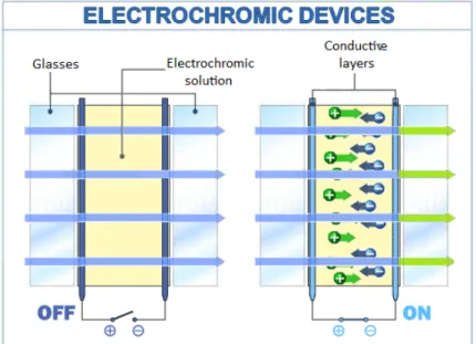
Electrochromism is defined as a reversible and visible change in transmittance of a material, as a result of electrochemical oxidation and/or reduction.[1] The electro-active species change their optical absorption bands due to a gain or a loss of an electron. After applying an electric field-current (dc field), which allows the transfer of the electron to the electrode work, the devices become colorful and persist in this condition until it is applied an opposite electrical impulse, or a competitive reaction occurs.
Without the application of an external electric field, electrochromic devices generally present themselves transparent (OFF state). Thanks to a subsequent application of a low voltage, the electrochromic device undergoes a color change (ON state) (Fig. 2.1).
In these systems, the chemical reaction is oxidation, a reaction in which the molecules of a compound lose an electron. Ions allow the change from transparent to colored state in the intermediate electrochromic layer. By applying a source of energy to the conductive oxide layers, the potential difference transports ions from their storage medium to electrochromic materials, through the conductive layer. This transfer enables the coloration of glasses.
Fig. 2.1 Scheme of an electrochromic device in the OFF and ON state
Following the removal of the electric signal, the ions are removed from the electrochromic layers and return to the storage medium. As a result, the device regains its transparency.
The ionic diffusion involved here, or the inherent absorption rate or loss of the electrons, will determine the speed of color change. The species is colored during the redox reaction is often called electro-chromophore or electrochromic material.[2] The colored state, which occurs after the transfer of electrons, persists, due to the memory effect. An adequate current, opposite in direction, reverses the electrochemical process and the display returns to the colorless or bleached state.
The electrochromic have many advantages:
• They consume little energy in the production of images that, once formed, persist with little or no addition of energy due to the so-called "memory effect";
• Large electrodes or many small electrodes[3] can be used. In general, there
is no theoretical limit to the size.
The initial development of the electrochromic devices was directed toward applications now used by liquid crystal display, that is, small displays, such as watches, clock slides or screens of personal computers. The anti-glare electrochromic mirrors in cars are another important application.[4,5]
Electrochromic sunglasses can be darkened at will, unlike the photochromic lenses. In addition, entire electrochromic windows can be tinted to reduce light into a room, office or otherwise in a windshield of a car. [6]
It is well known that visible light can be considered as a set of electromagnetic waves of wavelengths ranging from 420 nm (violet) to 700 nm (red) or as a set of photon energies from 4.7x10⁻¹⁹J (purple) to 2.8x10⁻¹⁹ J (red).
The color is subjective visual impression of the eye involving the retinal response to certain wavelengths of impinging light . The resulting colors depend on the material absorption and reflection. In white light, the perceived color of a material is the complementary color of the light that it absorbs (Fig. 2.2).[7]
Fig.2.2 The color wheel
A quantitative measure of the color intensity change is the contrast ratio, CR, defined as:
CR =
R0Rx (4)
where Rx is the intensity of light diffusely reflected in the colored state and Ro
is the intensity of light diffusely reflected in the bleached state.[8]
The right side of equation 4 can be replaced with e2αl where α is the linear
absorption coefficient and l is the film thickness. The factor 2 is due to the fact that the photons pass twice through the colored layers.
The time taken to color an electrochromic device from its colorless state (or vice versa) is called reaction time, τ.
In electrochromic windows or mirrors, reaction times of the order of seconds (minutes for windows) can be accepted, but they must be shorter for optical devices or television screens. Recently a display that show an ultra-fast color change has been presented.[9,10]
The use of indium tin oxide, ITO, as transparent conducting electrodes limits the response time, because of its moderate conductivity. [11]
When a device continually alternates states of electrochromic coloring and bleaching, device damage may occur due to physical changes in solid phases or secondary chemical reactions.
The life cycle of an electrochromic device is a measure of its stability, because it represents the number of cycles prior to its degradation. An important item of the manufacturers is obviously to raise the life cycle of electrochromic devices.
Tracy and al. [12] showed that the most important cause of device degradation
is the combination of continuous cycles of coloration/discoloration, high temperatures and irradiation.
2.1.1 Electrochromism in Liquid Crystal
Recently, the behavior of Electrolyte / Liquid Crystal Dispersions, ELCD, was studied.[13,14] ELCD show independent electro-optical and electrochromic properties, characterized by bright colors and fast coloring and bleaching times.
Liquid crystals, doped with a small amount of quaternary ammonium salts [15]
or ionic liquid, show a reversible color change when a dc electric field is applied.[16,17]
The colorful species will occur at the cathode, and electrochromism is observed in both the liquid crystal and isotropic state.
In particular, the color density increases linearly with the current, the dominant electrochemical reaction for the discoloration is a first-order reaction.
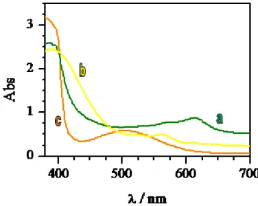
provide a change of color due to the electrochromic reactions at the electrodes.[13,18] The samples appear initially transparent but they will be characterized by different colors depending on the liquid crystal used after an application of a dc electric current (2 Volts) (Fig. 2.3).
Fig. 2.3 Absorption in the ON state by ELCD with different LC: a)E7, b)E49, c)ZLI4788-000
The increase of electrolyte concentration in the samples causes a decrease in the rise and decay times due to more rapid formation and disappearance of the local fields acting on the cell.[19]
The absorption reaches a plateau in a few seconds, depending on the electrolyte concentration and the application time of the dc current. Removing the field, the sample bleaches spontaneously in about ten seconds, depending on the electrolyte concentrations.
According to the mechanism coloring/discoloration proposed by Nakamura and al. [24] the application of a dc current in the ELCD causes the motion of the ions of the ammonium salt (or ionic liquid) A+ to the cathode, where the following reaction between A + and the liquid crystal (LC) occurs:
A+ + LC + e- → A*LC (colored)
giving a colored complex.
At the same time the molecules of halide, Ha2, are produced at the anode.
discoloration of the sample when the dc external field is removed, according to the following reaction:
2A*LC + Ha2 → 2(A + LC) + 2 Ha- (colorless).
References
[1] T. Rades, Y. Padmadisastra, C. C. Müller-Goymann, Pharmazie, 51, 846, (1996)
[2] M. -A. De Paoli and W. A. Gazotti, Macromol. Symp., 189, 83 (2002)
[3] G. G. Wallace, G. M. Spinks, L. A. P. Kane-Maguire and P. R. Teasdale,
“Conductive Electroactive Polymers 2nd edition”, CRC Press. (2003)
[4] H. J. Byker, U.S. Patent No 4,902,108 (1990)
[5] T. Nagamura, Y. Isoda and K. Sakai; Polym. Int., 27, 125 (1992) [6] F. G. K. Baucke, Schott Information, 1, 11 (1983)
[7] F. G. K. Baucke; Solar Energy Mater., 16, 67 (1987)
[8] R. B. Goldner, F. O. Arntz, G. Berera, T. E. Haas, G. Wei, K. K. Wong and P. C. Yu; Solid State Ionics, 53-56, 617 (1997)
[9] T. Oi; Ann. Rev. Mater. Sci., 16, 185 (1986)
[10] F. B. Kaufmann, Conference Record: Biennal Display Research Conference, 23 I.E.E.E. (1978)
[11] D. Cummins, G. Boschloo, M. Ryan, D. Corr, S. N. Rao, D. Fitzmaurice; J. Phys.
Chem. B, 104, 11449 (2000)
[12] N. Sbar, M. Badding, R. Budziak, K. Cortez, L. Laby, L. Michalski, T. Ngo, S. Schulz and K. Urbanik; Solar Energy Materials and Solar Cells, 56, 321(1999) [13] F. P. Nicoletta, G. Chidichimo, D. Cupelli, G. De Filpo, M. De Benedittis, B.
[14] F. P. Nicoletta, D.Cupelli, G. De Filpo, G. Chidichimo; Applied Physics Letters, 84, 4260 (2004).
[15] C. Fairhurst, S. Fuller, J. Gray, M. C. Holmes, G. J. T. Tiddy, “Lyotropic
Surfactant Liquid Crystals”, In “Handbook of Liquid Crystals”, D. Demus, J.
Goodby, G. W. Gray, H.-W. Spies, V. Vill, Eds.; Wiley-VCH: Weinheim; 3, CVII, 341, (1998)
[16] H. Meng, D. Tucker, S. Chaffins, Y. Chien, R. Helgeson, B. Dunn, and F. Wudl,
Adv. Mater., 15, 146 (2003)
[17] A. A. Argun, P. -H. Aubert, B. C. Thompson, I. Schwenderman, C. L. Gaupp, J. Hwang, N. J. Pinto, D. B. Tarmer, A. G. Mac Diarmid and J. R. Reynolds, Chem.
Mater., 16, 440, (2004)
[18] G. Chidichimo, D. Cupelli, M. De Benedittis, G. De Filpo, J. Lanzo, F. P. Nicoletta, B. Gabriele, G. Salerno, L. Veltri; World Patent, WO2006008776 (2006).
2.2 Ionic liquids
[1]Ionic liquids, IL, are salts, that are in a liquid state at low temperatures, and are formed by organic cations (usually imidazole, pyridine, phosphonium and ammonium ions) and inorganic anions.
Ionic liquids have a high thermal stability as they have a melting point below 100°C and boiling points above 200°C. Furthermore, they are good solvents and poorly volatile, since they have a negligible vapor pressure.
Research in the field of ILs began in 1982 with the study of J. S. Wilkes on the synthesis of aluminium chloride ILs. ILs stable in air and in mixtures were produced only in ‘90s, while few years ago specific ILs (or third generation) have been synthesized (Fig. 2.4).[1,2]
Fig. 2.4 Three examples of ILs of different generations: a) Aluminium chloride ILs, b) ILs stable in air and in mixtures, c) specific ILs
If one considers the various combinations of all cations and anions, it could be possible to create up to 108 types of ionic liquids (Fig. 2.5): about 1000 different ionic liquids are described in the literature, and approximately 300 are commercially available.[3]
Fig. 2.5 Typical structures of ionic liquids [3]
2.2.1 Property of Ionic liquid [4]
An ionic liquid must have the following characteristics: • Not volatile;
• Not flammable;
• High chemical, thermal and electrochemical stability; • Liquid phase in a wide temperature range;
• Dissolution of many organic and inorganic compounds; • Variable miscibility with water and organic solvents.
The stability largely depends on the used type of cation and anion.
Many studies have demonstrated that ionic liquids, in contrast to organic solvents, do not alter the integrity of cell membranes. This property is very useful in medicine and bio-pharmaceutics, opening new possibilities in building strategies for new pharmaceutical formulations. [5-8]
References
[1] V. Busico, P. Cernicchiaro, P. Corradini, M. Vacatello, J. Phys. Chem., 87, 1631, (1983)
[2] J. D. Gault, H. A. Gallardo, H. J. Müller, Mol. Cryst. Liq. Cryst., 130, 163, (1985) [3] Welton, T., Chem.Rev, 99, 2071, (1999)
[4] Dupont, J., J.Braz.Chem.Soc, 15, 341, (2004)
[5] Q. Yang, D.D Dionysiou, Journal of Photochemistry and Photobiology, A: Chemistry, 165, 229, (2004)
[6] www.ionicliquids-merck.de
[7] H. B. Zhang, X. H. Zhou, J. F. Dong, G.Y. Zhang and C.X. Wang, Sci China Ser B-Chem, 50, 238, (2007)
[8] M. D. Baumann, A. J. Daugulis, P. G. Jessop, Appl. Microbiol Biotechnol 67, 131, (2005)
2.3 Magnetism
Magnetism is a property of materials that respond at an atomic or subatomic
level to an applied magnetic field.
Magnetism has been known and exploited for centuries. The first known natural magnets, “loadstones” (magnetic iron oxides) were discovered by the ancient Chinese and Greek civilizations. These materials were found to point always in one direction when allowed to rotate freely. This led to the development of the magnetic compass. In the seventeenth century it was discovered that the earth itself is a giant magnet with north and south poles; and in the early nineteenth century the relationship between magnetism and electricity was established. Then a more theoretical understanding of magnetism and electricity has begun to emerge (Fig. 2.6).
Fig. 2.6 Magnetic field produced by a solenoid
The twentieth century witnessed the magnetic applications in a wide range of areas such as electronics, nuclear magnetic resonance spectroscopy and materials science.
Magnetism arises from two sources:
• Electric currents or, more generally, moving electric charges;
• Many particles have nonzero “intrinsic” (or “spin”) magnetic moments. Sources of magnetism are: electrons’ motions around the nucleus, electrons' intrinsic magnetic moments, nuclear magnetic moments but they are typically
smaller than the electrons' ones, so they are negligible in the context of the magnetization of materials.
Either spontaneously, or owing to an applied external magnetic field, each electronic magnetic moments will be, on average, lined up. Then the material can produce a net total magnetic field, which can potentially be quite strong.
The magnetic behavior of a material depends on its structure, particularly its electron configuration, and also on the temperature. At high temperatures, random thermal motion destroys the alignment.
Ferromagnetism is the most familiar type of magnetism. Although elemental iron is traditionally considered as the “stuff of magnets”, many other materials exhibit magnetic properties including nickel and cobalt[1], and more recently, even
organic materials[2]. Nonetheless, many applications are still based on iron even if the magnetic strength of iron magnets is relatively low.
The term magnet is typically reserved to objects that produce their own persistent magnetic field even in the absence of an applied magnetic field. Only certain classes of materials can do this. Most materials produce a magnetic field in response to an applied magnetic field.
Several forms of magnetic behavior have been observed in different materials, including:
• Ferromagnetic and ferrimagnetic materials are normally thought magnetic
materials; they are attracted by a magnet. These materials retain magnetization and become magnets; a common example is a refrigerator magnet. Ferrimagnetic materials have weaker magnetic properties than ferromagnetics. The difference between ferro- and ferrimagnetic materials is related to their microscopic structures.
• Paramagnetic substances, such as platinum, aluminium, and oxygen, are
weakly attracted by a magnet. This attraction is 105 times weaker than that of ferromagnetic materials, so it can be detected only by using sensitive instruments or extremely strong magnets (Fig. 2.7). Magnetic ferrofluids, although they are made of tiny ferromagnetic particles suspended in
liquid, are sometimes considered paramagnetic since they cannot be magnetized.
• Superparamagnetism appears in small ferromagnetic or ferrimagnetic
nanoparticles. In sufficiently small nanoparticles, magnetization can randomly flip its direction under the influence of temperature. The Curie temperature, Tc, is an important parameter that characterizes the ferromagnetic materials: above of Tc the material lose the spontaneous magnetization. The paramagnetism is thus an intrinsic property, while the superparamagnetic depends on external conditions such as temperature or size. Furthermore, their magnetic susceptibility is much larger than the one of paramagnets.
• Diamagnetic means repelled by both poles. Compared to paramagnetic
and ferromagnetic substances, diamagnetic substances, such as carbon, copper, water, and plastic, are even more weakly repelled by a magnet. The permeability of diamagnetic materials is less than the permeability of a vacuum.
Fig. 2.7 Magnetic needles that feel a magnetic field
atomic moments in the material contribute to its overall response, resulting in the magnetic induction B = μ0(H + M), where μ0 is the permeability of free space, and
the magnetization M = m/V is the magnetic moment per unit volume, where m is the magnetic moment of a volume V of the material.
Materials may be conveniently classified in terms of their volumetric magnetic susceptibility, χ, where M = χH describes the magnetization induced in a material by H. In SI units, χ is dimensionless, B is expressed in Tesla (T), and both M and H are expressed in A/m.
Magnetic beads have additional advantages: having embedded magnetic entities, they can be magnetically manipulated using permanent magnets or electromagnets, independent of normal microfluidic or biological processes. This additional degree of freedom is the basis of a still improved exposure of the functionalized bead surface to the surrounding liquid, due to the increased relative motion of the bead with respect to the fluid. It is important to note that a magnetic field gradient is required to exert a translation force, because a uniform field solely gives rise to a torque, but no translational action. The magnetic force acting on a point-like magnetic dipole or “magnetic moment” m in a magnetic induction B can be written as a function of the derivative of the magnetic induction:[3-7]
(5)
As an example, for a constant moment m in the x-direction, leading to m·∇=mx((∂)/(∂x)), a force will be exerted on the moment, provided there is a magnetic field gradient in the x-direction.
The susceptibility of a particle is also called effective susceptibility and is related to the intrinsic susceptibility of the material χmat by χ = χmat/(1 + Ndχmat),
with Nd the demagnetization factor (1/3 for a spherical particle).[8]
In case of superparamagnetic particles in a biological medium, one can describe the moment at small fields by the linear relation m = Vμ0 M = Vμ0ΔχH,
susceptibility between the magnetic particle and the surrounding liquid medium. Using the relation B = μ0H, eq 5 for a superparamagnetic particle in the linear
susceptibility regime becomes:
(6)
The magnetic moment of a superparamagnetic nanoparticle generally is smaller than that of a larger ferromagnetic microparticle. Hence, the magnetic force on a superparamagnetic particle will be smaller, which will result in slower magnetic separation processes. However, the advantage of superparamagnetic particles is the possibility to simply “switch off” the magnetic effects by removing the magnetic induction field.
In many applications, a magnetically labeled material is separated from a liquid solution by passing the fluid mixture through a region with a magnetic field gradient that can immobilize the tagged material via magnetic forces. For in vivo applications, magnetic particles can be transported by the blood flow and locally retained with the help of an external magnet. In other applications, there is a magnetic translational driving force, and the liquid solution is static. In the equilibrium state, the magnetic force Fm is opposed to the hydrodynamic drag
force Fd acting on the magnetic particle.
The hydrodynamic drag force is a consequence of the velocity difference between the magnetic particle and the liquid Δv and, for a spherical particle with radius r, is given by:[9]
(7)
where η is the viscosity of the medium surrounding the particle (for water, η = 8.9 × 10⁻⁴ N s/m2). f
D is the drag coefficient of the particle and incorporates the
influence of a solid wall in the vicinity of the moving particle.[10,11]
In a microfluidic system, a particle may be moving under influence of the applied magnetic forces, so that the viscous force of eq 7 will vary along the particle trajectory. Equalizing eqs 6 and 7 permits one to determine the maximum
flow rate that a particle can withstand when exposed to a magnetic immobilization force, or the maximum particle flow rate that can be generated by a magnetic force in a surrounding static liquid:
(8) with
(9)
the “magnetophoretic mobility” of the particle, a parameter describing how magnetically manipulable the particle is. The quantity (B·∇)B can be a strongly varying function in space, which implies a similar spatial variation for Δv.
References
[1] C.H. Setchell; J. Chem. Tech. Biothec., 35B, 175 (1985) [2] J.S. Miller, A.J. Epstein; Chem. Commun., 13, 1319 (1998)
[3] R. Becker; Electromagnetic Fields and Interactions; Dover: New York, (1982) [4] S. Chikazumi; “Physics of Magnetism”, R.E. Krieger Publishing Co.: Malabar,
FL, (1964)
[5] U. Häfeli, W. Schütt, J. Teller, M. Zborowski; “Scientific and Clinical
Applications of Magnetic Carriers”; Plenum Press: New York, (1997)
[6] Y. Moser, T. Lehnert, M.A.M. Gijs; Appl. Phys. Lett. 022505 (2009)
[7] S.S. Shevkoplyas, A.C. Siegel, R.M. Westervelt, M.G. Prentiss, G.M. Whitesides; Lab Chip 7, 1294 (2007)
[8] Jackson, J. Classical Electrodynamics; Wiley: New York, (1998) [9] F.M. White; Fluid Mechanics; McGraw-Hill: New York, (1999) [10] H. Faxen; Ann. Phys. 68, 89 (1922)
[11] R. Wirix-Speetjens, W. Fyen, K.D. Xu, J. De Boeck, G. Borghs; IEEE Trans.