Development of a new tracking device for
characterization and monitoring of ultra fast
neutron beams
Dottorato di Ricerca in Fisica degli Acceleratori – XXXII Ciclo
Candidate
Riccardo Mirabelli ID number 1460424
Thesis Advisor
Prof. Vincenzo Patera
Co-Advisor
Dr. Michela Marafini
Prof. Nome Cognome (chairman) Prof. Nome Cognome
Dr. Nome Cognome
Development of a new tracking device for characterization and monitoring of ultra fast neutron beams
Ph.D. thesis. Sapienza – University of Rome ISBN: 000000000-0
© 2013 Riccardo Mirabelli. All rights reserved
This thesis has been typeset by LATEX and the Sapthesis class. Version: January 17, 2020
iii
Contents
Introduction v
1 Ultra Fast neutrons: beams and applications 1
1.1 Neutron radiation and biological effects . . . 1
1.1.1 Neutrons in Radio-Therapy and Particle Therapy . . . 3
1.1.2 Neutrons in Space . . . 4
1.2 QMN fields . . . 8
1.2.1 Existing facilities . . . 8
1.3 The SPARE project . . . 14
1.3.1 Shielding . . . 14
1.3.2 NEPIR: A Neutron Facility at INFN-LNL . . . 15
2 Neutron Beam Monitoring and the MONDO detector 19 2.1 Detector for beam characterisation and monitoring . . . 19
2.2 Measurements for SPARE project . . . 21
2.3 MONDO project: description and development . . . 22
2.3.1 Detection technique . . . 22
2.3.2 Tracker Development . . . 25
2.3.3 Signals Characterisation . . . 29
3 The SBAM sensor 35 3.1 Physics requirements and SPAD technology . . . 35
3.2 Preliminary measurement on SPAD-based sensor prototype . . . 37
3.2.1 SPADnet-I sensor . . . 37
3.2.2 Deposited Energy and Bragg Peak position reconstruction . . 37
3.2.3 dE/dx preliminary measurement . . . . 38
3.3 SBAM Sensor architecture and characteristics . . . 40
3.3.1 Photon detection probability . . . 41
3.3.2 Trigger system . . . 43
3.3.3 Configuration and Data readout . . . 45
3.4 SBAM-I prototype . . . 45
3.4.1 T1 trigger test . . . 46
3.4.2 TDCF time resolution . . . 47
4 MONDO neutron tracker performances evaluation 57
4.1 Background study . . . 57
4.2 Efficiency . . . 58
4.3 Single Elastic Scattering performances . . . 59
4.3.1 Energy resolution . . . 59
4.3.2 Reconstruction of NEPIR energy spectra . . . 61
4.4 Double Elastic Scattering performances . . . 63
4.4.1 Energy Resolution . . . 63
4.4.2 Backpointing resolution . . . 64
4.5 dE/dx studies . . . . 66
4.6 Neutral and Charged Particle Tracker . . . 71
4.6.1 MONDO performances as Photon Detector . . . 71
5 SBAM-I Tests and Characterisation 77 5.1 DCR Characterisation . . . 77
5.1.1 Counters comparison . . . 77
5.1.2 Temperature Dependance . . . 78
5.2 TDCs test with Pulsed laser . . . 79
5.3 Pulsed Led measurements . . . 82
5.3.1 Charge calibration . . . 82
5.3.2 Time resolution . . . 82
5.4 90Sr Source reconstruction measurement . . . . 86
5.5 Sensor Tile studies and development . . . 87
Conclusions 91 A Tracker development 93 A.1 PENELOPE prototype . . . 93
A.2 ULISSE prototype . . . 95
A.3 ARIANNA Technical design report . . . 96
v
Introduction
Neutron radiation fields are generated in various scientific research areas and ap-plications, for example in radiation therapy, in radionuclide production for medical applications, in material science studies, for design of electronic components in energy production, military activities, and in neutron radiography. Moreover, high energy neutrons are the dominant component of the prompt radiation field present outside the shielding of high-energy accelerators and are a significant component of the cosmic radiation fields interacting with aircrafts and in spacecrafts.
The Space Agencies programs are focusing on human space exploration. The return to the moon and the construction of a permanent base (Moon Village) and the Mars exploration are now among the highest priorities both for NASA and ESA. However, the health risks caused by exposure to cosmic radiation are acknowledged as one of the major showstopper for safe colonization of the Solar systems. Shielding is the only practical countermeasure available, but there is still a lack of information regarding the neutrons stopping performances of the new materials currently under evaluation in the context of long term space missions (e.g. highly hydrogenated materials, in situ resource utilizations and active shields). The recently founded SPARE project aims to carry out a shielding test campaign of active and passive materials using high energy protons and neutrons at the accelerator facilities in Trento (TIFPA) and Legnaro (SPES- Laboratori Nazionali di Legnaro LNL). For this reason the development of a new Quasi Monoenergetic Neutron (QMN) sources capable of accelerating neutrons with energies up to 70MeV in LNL will be a major goal of the project since no other QMN facility is currently in operation in Europe. An innovative detector (MONDO) developed by the "Museo Storico della Fisica e Centro Studi e Ricerca E.Fermi", able to track both neutrons and charged particles, will be used to measure the radiation transmitted and emitted by the shielding. The aim of this thesis is to present the MONDO neutron tracker and to describe its application within the SPARE project with a particular focus on its application as Neutron Beam Monitor for the new NEPIR QMN facility planned at LNL.
Chapter 1 is dedicated to the description of the basic principles of neutron physics and dosimetry with a focus on the possible applications in space and Particle Ther-apy. An overview about the existing Quasi Mono-energetic Neutron facilities is also presented. The chapter conclusion contains an overview of the SPARE project. Chapter 2 is dedicated to the MONDO detector: the detection techniques and the tracker development status are described. The characterisation measurements already performed on a small MONDO prototype are also presented.
In Chapter 3 a detailed description of the MONDO readout system, the SBAM sensor, is presented.
Chapter 4 is dedicated to the presentation of the detector performances evaluated by means of a full-Montecarlo simulation in FLUKA.
In the last Chapter ( 5) measurements on the first sensor chip with different source are illustrated.
1
Chapter 1
Ultra Fast neutrons: beams and
applications
In last years high-energy neutron fields are gaining more attention due to the increas-ing number of accelerators in research and medicine and the special consideration given to the occupational exposure to cosmic radiation.
High-energy neutrons are the dominant part of the prompt radiation field present outside the shielding of high-energy accelerators and a significant component of the cosmic radiation fields in aircraft and in spacecraft (Section 1.1.2). In radiotherapy, high-energy neutrons are a secondary component of the fields in the beam delivery system and in the patient’s body (Section 1.1.1). In order to study the physics of neutron interactions in these applications, in particular concerning dosimetry, radiation protection and radiation effects in electronics, well-characterised neutron fields for high energies are needed. The first part of this chapter is dedicated to overview the physical and biological effects of high-energy neutrons, focusing on space and medical application. In the second part, a particular type of neutrons source will be described while in the last part the new-coming SPARE project will be presented.
1.1
Neutron radiation and biological effects
Neutron dosimetry is of practical relevance for a large number of application, spanning on a wide energy range of at least ten orders of magnitude. However, studies concerning neutron radio-protection and dosimetry suffers from neutron detection difficulties and the high variability in neutron radiation biological effects. Therefore, there is no dosimeter capable of measuring neutron doses independently of the neutron spectrum with adequate accuracy.
The definition of equivalent dose:
HT =
X
R
wRDT ,R (1.1)
shown that the dose released in various organs is obtained scaling the absorbed dose DT with the radiation weighting factor wR that changes with the type and the
Table 1.1. Radiation weighting factors, as recommended in the ICRP-103 report [1]
Radiation Type wr
X and γ rays 1
Electrons and Muons 1 Protons and Charged Pions 2
α particles and heavy ions 20
Neutrons 2-20
Neutron Energy [MeV]
Radiation weighting factor
Figure 1.1. Neutron radiation weighting factor wR as a function of the neutron energy
according to the latest International Commission of Radiological Protection recommen-dation [1]. The most effective neutrons are considered to be those with energies around 1 MeV [2].
1.1 Neutron radiation and biological effects 3
As it can be seen in Figure 1.1, neutrons have a strongly energy-dependent wR, described by the equation:
wr= 2.5 + 18.2 · exp(−(lnEn)2 6 ) En< 1 MeV 5.0 + 17.0 · exp(−[ln(2En)]2 6 ) 1 MeV ≤ En≤ 50 MeV 2.5 + 3.25 · exp(−[ln(0.04En)]2 6 ) En> 50 MeV (1.2)
Neutrons with energies from few keV to few MeV are the most dangerous and they can reach a weighting factor up to 20 (Figure 1.1). Dosimetry research for radiation protection purposes have to take into account specific application and realistic operational situations. For examples, as will described in next sections, studies applied to Particle Therapy and radio-protection in space could benefit from an improvement of the information on fast and ultrafast neutrons detection and dosimetry.
1.1.1 Neutrons in Radio-Therapy and Particle Therapy
In the past few years, tumor therapies exploiting high energy photons or charge particle beams become more and more diffused and their effectiveness in the treatment of radio resistant tumor or pediatric case has been demonstrated [2].
Nowadays, approximately 80% of children with cancer will survive 5 years or longer, compared with 30% in 1960 [3]. Nevertheless, a significantly risk of second malignant neoplasms (SMNs) has been observed for long-term survivors of childhood cancer who received radiotherapy: the incidence of SMNs 30 years after the treatment is around 10 − 20%.
Secondary neutrons, which are unavoidably present in radio-therapy treatments, give a substantial contribution to the dose deposition in body regions that are not directly crossed by the therapeutical beam, and represent one of the most abundant and harmful radiation exiting the patients body, contributing to increase the risk of SMN.
The production of neutrons from photons at energy above 8 − 10 MV is due to photo-nuclear reactions that occur in collimators materials and in the beam delivery system. Neutrons produced from photon interaction (Photo-neutrons) can contribute to the total dose released in patient body at distance > 20 cm from the target, with a dose distribution that tends to flatten rather than decrease at greater distance. Light ions used in Particle Therapy of solid cancer also produce secondary particles by nuclear fragmentation, and these particles can deposit their energy in the normal tissue. Neutron yield is caused mainly from 12C projectile fragmentations [4] in Carbon therapy or from proton-induced nuclear reactions (e.g. proton charge-exchange) [5] in proton therapy.
Secondary neutrons can undergo nuclear collisions with protons and light ions in the human tissue, generating additional charged particles that can ionize surrounding molecules. The production of secondary neutrons in radio-therapy and Particle Therapy strongly depends not only on the specific treatment (energy and intensity of the primary in therapeutic beam, distance of the organ under consideration, etc.) and on characteristics of the patient (age, sex, physical conformation) but also on therapy center [6]: this variation is attributed to many factors, including
differences in the treatment units, experimental techniques and in reporting protocols of dosimetric informations.
The characterisation of neutron production hence plays an important role in the assessment of the risk of second cancers in Particle Therapy administration and planning. In Figure 1.2 the measured neutron production spectra induced by 25 MV photon IMRT beam [7] and from 200 MeV/u carbon ion beam [8] are shown. The neutron energy spectrum in radiotherapy with photons is in the range below a few MeV while for PT treatment, the produced neutrons are mainly fast and ultra-fast and are found, for example, in carbon ion treatment (energy up to 220 MeV), within the 20 − 400 MeV range.
Figure 1.2. The energy spectrum of photo-neutrons produced by Megavoltage X-rays and
secondary neutrons produced by nuclear interactions of charged particles is complex. The figure shows recent neutron spectral measurements at the ELEKTA Linac accelerator in the Klinikum Goethe Universitat of Frankfurt, Germany, operated at 25 MV, and at GSI, Darmstadt, Germany, with a 200 MeV per nucleon12C pencil beam stopping in a water target [2].
However, measurements from non-directional detector are affected by the back-ground of neutrons produced and scattered in the environment. The backback-ground rejection cuts are hardening the efficiency evaluation, eventually resulting in an increase in the cross section measurement systematic uncertainty.
1.1.2 Neutrons in Space
Neutrons represent an important component of the radiation spectrum in space and their dosimetry is particularly challenging in space flights.
Neutrons are mostly produced from the nuclear interaction between Galactic Cosmic Radiation (GCR e.g. radiation originates outside the solar system) with spacecraft
1.1 Neutron radiation and biological effects 5
walls, astronauts human body and atoms of Earth’s atmosphere. Energies of secondary neutrons produced cover the complete range from thermal neutrons to several GeV.
Neutrons in space represent only the ∼ 7% to the total absorbed dose but their contribution increase to ∼ 30% of the equivalent dose. The models predict that neutron dose rates of nearly 0.5 mSv/day are possible on the ISS with lower estimates below 0.1 mSv/day [9].
The problem of neutrons becomes even more complex considering Mars expeditions and exploration. The particular martian atmosphere stop the low energy charged particles and modify the composition of particle fields penetrating to martian surface. Moreover, the impact with martian surface materials provide additional modifications in the field composition, including the augmentation of neutrons which diffuse from the surface materials back into the atmosphere [10]. Since the martian surface composition and topology is extremely variable, energy and flux of diffusive neutrons depend critically on the specific area and is also seasonally dependent due to the presence of protective ice (water or permafrost).
Neutron Detectors in space
Neutron detection and dosimetry in space is usually performed using detection methods able to measure charged particle produced by neutrons. Recoil-based detector can span a very wide energy spectrum and their response is energy-dependent. From other hand, this kind of measurements have high intrinsic background composed from the other charged particles with energies similar to the ones of recoiled particles. In Table 1.2 data obtained in different space mission using nuclear emulsion detector for neutron and charged particle are shown. As already explained in Section 1.1, in term of equivalent dose neutrons contributions is non negligible and the the ratio between equivalent dose and flux is higher respect to charged particles.
Table 1.2. Comparison between dose and dose equivalents for neutrons and charged particles in four different STS missions at 28.5 inclination in LEO. Neutron dose was measured by nuclear emulsions and charged particle dose by TLD-100 detectors [11]
Mission Altitude (km) Neutron dose rate (µGy/day) Charged Particle dose rate (µGy/day) Neutron equivalent dose rate (µSv/day) Charged particle equivalent dose rate (µSv/day) STS-55 302 5.9 57.2 52.0 120.1 STS-57 470 25.3 461.9 220.0 859.4 STS-65 306 11.0 75.2 95.0 157.8 STS-94 296 3.7 101.5 30.8 213.9
An example of detector exploiting the recoil particle to reconstruct neutron spectra is SONTRAC (SOlar Neutron TRACking), proposed in [12] and designed to operate in in neutron energy range [20 − 250] MeV and based on the reconstruction of neutron-proton double elastic scattering in a block of scintillating fibers. The
project, proposed as test of the detection techniques, exploits the double-scattering in order to uniquely determine neutron energy and direction on an event-by-event basis. Neutrons can interact with the hydrogen of the scintillating block. Protons produced interact with the block itself and the optical photons produced can be detected with a system of CCD camera. A schematic representation of the detector and a photo of the test apparatus are shown in Figure 1.3.
The reconstruction of both energy and direction of the incoming neutrons result in a background reduction, as it is possible to distinguish neutrons signals from charged particle tracks.
Figure 1.3. (Left) The SONTRAC 3D Science Model, seen from above. The plastic
scintillator fiber bundle is visible in the center of this image. To the top and left are the two PMTs used for trigger. To the right and bottom are the two optic chains with image intensifiers, coupled to two CCD cameras. (Right) Schematic representation of a non-relativistic double elastic n-p scatter in SONTRAC plastic scintillator cube. By measuring the energies and directions of the two recoil protons (shown in yellow gold), one can reconstruct the direction and energy of the incident neutron. [13]
In last years neutron energy spectra measurements have been performed with Bonner spheres on International Space Station (ISS) [14]. Comparison of obtained spectra with the data obtained from different measurement on Space Shuttle and MIR is shown in Figure 1.4. For E > 1 MeV spectra obtained from ISS and MIR data set shown that neutron spectrum has higher flux at greater shielding depth, demonstrating that in high-energy range, thicker shield produces more neutrons, while spectra are similar at low energy.
However, the neutron flux recorded at ISS is much lower than MIR even though the shielding is similar. The discrepancy is likely to be due to the different instruments used: Bonner ball neutron detectors on ISS and nuclear emulsions on MIR and the Space Shuttle.
1.1 Neutron radiation and biological effects 7
Figure 1.4. Comparison of the neutron spectrum obtained inside the ISS with the
mea-surements obtained inside other spacecrafts; the fitted neutron spectrum evaluated from the measurement inside the STS-28 in 1989, as well as the neutron spectra measured inside the MIR space station in 1991 under 40 g/cm2 shielding thickness, from 1990 through 1993 under 30 g/cm2 shielding thickness, and from 1990 through 1992 under 20 g/cm2 shielding thickness.[14]
needed. Since the logistic difficulties to test new detector and acquire cosmic neutron spectra directly in space, specific facilities for high-energy neutron irradiation must be used for preliminary test and specific fragmentation measurements. In particular, facilities must provided neutrons with specific energy, since the effect of neutron radiation exposure in, for example, electronics device or on biological samples are strongly energy-dependent.
Next section will be dedicate to the description of the active Quasi Monoenergetic neutron facilities, providing neutron spectra with a sharp peak energy.
1.2
QMN fields
Quasi Monoenergetic Neutron (QMN) facilities are of great importance since they allow for detailed studies of energy dependent responses. This is of particular rele-vance for the studies of neutrons Relative Biological Effectiveness (RBE), strongly energy dependent, where there is still lack of information. High energy QMN fields can be produced from proton beams impinging on thin Li and Be targets, according to the reactions 7Li(p, xn) and 9Be(p, xn). In order to remove the non-neutrons
components of the beam, mostly protons that pass through the thin target without causing nuclear reactions, a magnetic deflector is usually placed after the target. The resulting neutron energy spectrum in the forward direction is not purely mono-energetic but it is composed of two different components that contain about half of the total neutron intensity each. On top of high energy peak component close to the energy of the incoming proton, there is also a broad distribution at lower energy (tail) coming from the nuclear breakup reactions. However, the fraction of high-energy neutrons in the mono-energy peak decreases rapidly with angle while the continuous tail of low energy neutron changes much less. The characteristic angular dependence can be used to correct data taken in the forward (0◦) direction by subtracting data obtained at larger angles (usually in the 15◦− 30◦ range). The width of the mono-energetic peaks comes from two contributing factors: the energy loss of the primary proton beam in the target, and the fact that the 7Li(p, n) and
9Be(p, n) reactions reach both the ground and first excited states. Even though Be
has better physical properties, as it is stable and more easily handled, thin Li targets are normally used at QMN facilities as the neutron yield of the mono-energetic peak is sharper for equal target thickness. The mono-energetic neutron peak from Be can be kept narrow by using thinner targets, resulting in a lower neutron yield.
1.2.1 Existing facilities
A small number of QMN facilities are in operation worldwide. After the ANITA decommissioning at TLS in Sweden, the only existing facilities are concentrated in Japan (TIARA, CRYIC, RCNP) and in South Africa (iThemba). A fifth QMN facility is under construction at GANIL in France but it will be restricted to energies below 40 MeV. In this section, a description of the aforesaid facilities is presented.
1.2 QMN fields 9
iThemba LABS, South Africa
At iThemba Laboratory for Accelerator-Based Science, protons are accelerated from 25 MeV to 200 MeV at Separated-Sector Cyclotron. The facility, accessibile to external user, has already been used for detector development, cross section measurements, radiation biology experiments, detector and dosimeter calibrations, especially for dosimetry at flight altitudes and air crew dosimetry. Neutrons fields are produced from Li target in an experimental room with different 2 m thick steel collimators at different angles (respectively at 0◦, 4◦, 8◦, 12◦ and 16◦) shapes 10 cm × 10 cm squared beams at 8 m. A schematic representation of the experimental room is shown in Figure 1.5. The experimental area has a width of about 9 m and a depth of 3 m in the direction of the beam. An annex, 3 m long and 1.3 m wide, exists in this area in front of the 0◦ exit of the collimator. For this reason, flight paths between 4 m and 11 m in length are possible.
Figure 1.5. Sketch of the iThemba Laboratory neutron beam facility. [15]
The iThemba facility can also be also used for the production of beams with a continuous energy distribution due to anatC target.
Five beams with neutron peak energies of about 35 MeV, 65 MeV, 97 MeV, 147 MeV and 197 MeV have been characterized with Time-Of-Flight (TOF) system.
TOF measurements has been performed enlarging the time intervals between beam pulses due to a pulse selector that can suppress a chosen factor of protons bunches. For the 97 MeV beam a FWHM of the high energy peak of ∼ 4 MeV is measured. The fraction of the total fluence within the peak in the straight direction is ∼ 40% but can be effectively increased to ∼ 70% if the response at 16◦ is subtracted. In Table 1.3 the characteristics of the neutron beam for standard energies are shown.
TIARA, Japan
Takashi Ion Accelerators for Advanced Radiation Application (TIARA) was con-structed in order to promote R&D on materials science and bio-technology using ion beams, coming into operation in 1993.
At TIARA, neutron fields are produced from [40-90] MeV proton beams impinging on a 7Li disk. Main applications for the high-energy neutron beams are shielding
Table 1.3. Typical fluence Φ at 8 m from a 6 mm natLi target at the given current and
proton energy E0. Φ0/Φ is the monoenergetic fraction of the flux. For radioprotection requirement, the maximal proton current is reduced to 300 nA when the highest neutron energies are produced. [15]
E0 MeV current (mA) dΦ/dt (cm−1s−1) Φ0/Φ
66 3.0 4.7 × 10⁴ 0.39
100 3.0 3.4 × 10⁴ 0.51
150 2.0 2.8 × 10⁴ 0.48
200 0.3 4.6 × 10³ 0.51
experiments, measurements of nuclear data and the characterization of neutron detectors using the TOF method. The Quasi Monoenergetic neutrons produced by the target reach an experimental room (Figure 1.6) through a iron collimator with a diameter of 10.9 cm and 3.07 m long. The distance between the target and the collimator exit is 4.835 m. The interval between beam pulses ranges from 45 ns to 90 ns depending from the proton energies. However, beam pulses spaced at interval over 1 µs can be obtained using chopping system [16].
Figure 1.6. Schematic diagram of the beam line used for the high-energy neutron field at
TIARA. [17]
CYRIC, Japan
The AVF cyclotron at Cyclotron and Radioisotope Center (CYRIC) can accelerate protons from 14 to 80 MeV. The first neutron beam has been produced in 1977 using a K = 50 MeV cyclotron. Last upgrade at K = 110 MeV AVF has been realized in 2004. In last decades, the QMN facilities worked as a powerful tool for studying the different aspects of the charge-exchange (p,n) reactions, the particle transfer
1.2 QMN fields 11
(d,n) reaction and the nuclear mean-field by the neutron scattering experiment. The source is also used for cross section measurements for nuclear physics, testing of semiconductors for single-event effects and dosimetry development. Figure 1.7 shows a schematic view of the actual neutron facilities. The typical neutron intensity produced from a 9.1 mm water-cooled7Li target is ∼ 1010sr−1s−1µA−1 with a beam energy spread of ∼ 5%. The beam collimator consist of 595 mm thick iron block. The beam characterization has been performed with TOF system 7.37 m posed downstream the7Li target. The energy spread of the neutron beam is 4 MeV and the ration between the peak area to the total fast neutron flux is ∼ 0.4.
Figure 1.7. Bird view of the CYRIC neutron flight rooms [18]
RCNP, Japan
At Research Center for Nuclear Physics (RCNP) of Osaka University protons can be boosted up to 400 MeV. Quasi Monoenergetic neutron fields can be produced from 10 mm7Li target. The experimental tunnel is 100 m long in order to enable precise measurement of energy distribution by TOF method (Figure 1.8). The beam has been calibrated for proton beam of 250 MeV, 350 MeV and 392 MeV with a TOF system with a 11.4 m length. The QMN peaks have been reconstructed with a width (FWHM) of 2.5 MeV. The characteristic of the reconstructed 248, 348 and 390 MeV peak energy spectra are described in Table 1.4.
NFS, GANIL, France
Neutron for Science (NFS) is a new facility that will offer both white neutron energy spectrum and a QMN spectrum which is under construction at GANIL, in France.
Figure 1.8. Schematic representation of the RCNP experimental room. [19]
Table 1.4. Characteristics of the Quasi Monoenergetic neutron field at RCNP. [19]
Proton energy [MeV] 250 350 392
Peak neutron energy [MeV] 248 348 390
Integration interval of peak neutron [MeV] 236 - 250 344 - 350 383 - 392 Peak neutron intensity [n/(sr µC)] 1.94 × 10¹⁰ 1.07 × 10¹⁰ 1.50 × 10¹⁰
FWHM of peak neutron [MeV] 2.5 2.5 2.5
Integration interval of tail neutron [MeV] 4 - 236 6 - 344 21 - 383 Tail neutron intensity [n/(sr µC)] 1.70 × 10¹⁰ 1.35 × 10¹⁰ 1.76 × 10¹⁰
1.2 QMN fields 13
The facility will be located in a converter cave where a neutron production target and set-ups for high intensities beam are located. The experimental area will allow performing time-of-flight measurements by using experimental set-ups at distance from 5 m to 25 m from neutron production point. At NFS Neutron could be produced both from protons on7Li target (QMN) and from deuterons break-up reaction on
thick C or Be target (continuous spectrum). Proton and deuteron beams up to 33 MeV and 40 MeV respectively are provided by the new linac Spiral 2 LINAG. Although the LINAG can deliver proton and deuteron beams with currents up to 5 mA, the ion beam intensity on the neutron production targets will be voluntarily limited to 50 µA. The reduced intensity means reduced wall thickness for radiation protection and reduced activation of the converter. It will also mean a manageable power distribution on the neutron production targets.
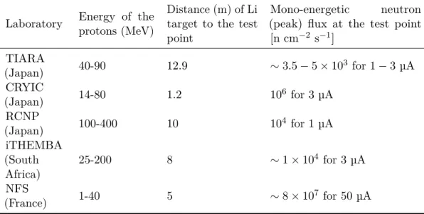
Table 1.5. QMN fluxes at existing QMN (En > 20 MeV) facilities in the world.
Laboratory Energy of the protons (MeV)
Distance (m) of Li target to the test point
Mono-energetic neutron (peak) flux at the test point [n cm−2 s−1] TIARA (Japan) 40-90 12.9 ∼ 3.5 − 5 × 10 3 for 1 − 3 µA CRYIC (Japan) 14-80 1.2 10 6 for 3 µA RCNP (Japan) 100-400 10 10 4 for 1 µA iTHEMBA (South Africa) 25-200 8 ∼ 1 × 10⁴ for 3 µA NFS (France) 1-40 5 ∼ 8 × 10 7 for 50 µA
In Table 1.5 a summary of the principal characteristics of the QMN facility described in this chapter is shown. In Europe there is not any facility providing neutrons up to 40 MeV. Present and future high-energy spallation source (ISIS, ESS) in spite of their high neutron yields and sophisticated instrumentation will barely fulfill the demands of the large neutron user community for materials research with very reduced beam time left for other fields and disciplines.
The commissioning of a new QMN facility in Europe could be extremely important for measurement in different fields as radioprotection, detector characterisation and material science. The SPARE project, described in the next section, has been recently funded. One of its goal is the construction of a new neutron beam line inside the INFN-LNL (Italy).
1.3
The SPARE project
SPARE (SPAce Radiation shiElding) is a INFN1, ASI2 and Centro Fermi3 flagship project founded by Italian Ministery of Research and Education aiming at the characterization of different shield for radio-protection in space.
Various shielding materials will be tested with high energy protons and neutrons in order to characterise the flux and the energy spectra of the secondary fragments produced. The experimental room of the Trento Protontherapy Center (APSS) has been locate as a suitable facility for the measurements with proton beams, since it is possible to irradiate different shield in the energy range [50 − 220] MeV. Moreover, since there is no place in Europe where it is possible to irradiate materials with neutron beams with energy above 40 MeV, part of the project is dedicated to the construction and development of a new QMN neutron facilities at INFN-LNL in Legnaro.
The sources can provide neutrons beam with energy up to 70 MeV that is the maximum energy reached from the proton beams provided from SPES cyclotron [20]. Both the measurements of the radiation transmitted and emitted by the shielding and the characterisation of the neutron beams at the planned facility will be performed with an innovative detector, MONDO, able to track both neutrons and charged particles, that will be described in chapter 2.
1.3.1 Shielding
Radiation protection strategies are divided in three different group: increasing the distance from the source, minimizing the exposure time or introducing radiation shielding. Since in Space the first two options are not practicable (cosmic rays are omnidirectional and the decreasing of exposure time in a long space mission is impossible), shielding remains the only viable option. Two different type of shielding has been proposed: Passive Shielding which consists of placing extra material to protect astronauts, including novel (e.g. highly hydrogenated materials) or in-situ material, as Martian and Lunar regolith; Active Shielding that involves the generation of electromagnetic fields to deflect the cosmic rays.
Passive shields can be obtained from different type of material. There are several factor that identify a good passive shield:
• Material Index: The material index, calculated using the formula (Z/ρ)A2/3
will be used in the preliminary trade-off phase, when MC simulations will not be available. It represent the probability that a particle is stopped in the material without undergoing a fragmentation process. The expression of the material index is calculated considering that the energy lost by one incident particle per cm2 per unit mass is proportional to (Z/ρ)A and that the nuclear transmission is proportional to 1/A1/3 [9];
• Heavy ions measurements or simulations: When available, heavy ions test data or simulations will be used in the trade-off processes instead of the material
1
Istituto Nazionale di Fisica Nucleare
2
Agenzia Spaziale Italiana
3
1.3 The SPARE project 15
index, in order to give a more precise evaluation of the shielding capability of the materials. A global score will be assigned to each material to take into account both dose-reduction and secondary production for thickness compatible with their use in space.
• Multifuctionality: e.g. the capability of a material to perform other functions other that radiation shielding. The choice of a multifunctional shield impacts directly on costs, weight and space occupancy.
• Environment Compatibility: both internal and external environment must be considered. The material must be compatible with the crew and the instrumentation inside the cabin and with the vacuum and thermal excursion of outer space.
• Launch environment compatibility: compatibility with the mechanical environ-ment of a launcher including static loads, shocks and vibrations and with the depressurization of the fairing. Also the weight is a fundamental parameter that affects the launch cost and success.
All these requests must be taken into consideration in the choice of the appropriate shield.
Another important parameter for the design of proper shields is the thickness of the material. A thin or moderate shielding is generally efficient in reducing the equivalent dose, but as the thickness increases, shield effectiveness drops because the production of secondary particles increase.
In the active shielding approach dedicated devices, such as superconducting magnets, can be used for generating intense magnetic fields capable of deflecting high energy GCRs. In this approach biological effects on humans of strong magnetic fields have been considered as well as the extra mass transport and the extra maintenance during space travel.
One of the main scientific goals for the SPARE project is the realisation of an intense measurements programs for the test and the characterisation of different active and passive shields. Measurement will be performed both in the experimental room of the ProtonTherapy center in Trento where a proton beam with energy up to 220 MeV is available and in a novel neutron beam line in INFN-LNL that will be described in the next section.
1.3.2 NEPIR: A Neutron Facility at INFN-LNL
SPES facility at INFN-LNL [20] is a project dedicated to the development of a second generation ISOL (Isotope Separation On Line) facility for the production of neutron-rich beams and devoted to the applied nuclear physics. The research program is divided in four different "phases" each with specific objective and a separate financial budget. In particular, the Delta-Phase includes the development of a new infrastructure for neutron and beam irradiations called NEPIR (NEutron and Proton IRradiation).
The SPES main cyclotron can provide high current (max 750 µA) proton beams in the energy range [30 − 70] MeV. In last years, the cyclotron has been commissioned and the first proton beams have been successfully delivered. In Table 1.6 the
Table 1.6. SPES cyclotron main characteristic [20]
Accelerator Type Cyclotron AVF 4 sectors Particle Protons (H-accelerated)
Energy Variable within 30 − 70 MeV
Max current accelerated 750 µA (52 kW max beam power)
Available beams 2 beams at the same energy (upgrade to different energies) Max magnetic field 1.6 T
RF frequency 56 MHz, 4th harmonic mode
Ion source Multicups H − I = 15 mA, axial injection
Dimensions Φ = 4.5 m, h = 1.5 m
Weight 150 tons
characteristic of the cyclotron are described.
Presently within the NEPIR project three beams facilities are proposed: • A Quasi Mono-energetic Neutrons (QMN) beams with a tunable energy peak
in the [30, 70] MeV energy range. Neutron peak energies below 30 MeV could be obtained using a Carbon energy degrader. The calculated maximum neutron flux in the energy peak in a test point 3 m from the target will be ∼ 2.7 × 10⁵ n cm−2 s−1 considering a current I=10 µA of 70 MeV protons.
• ANEM (Atmospheric Neutron EMulator), an intense beam of fast neutrons in the energy range [1, 65] MeV with a continuous energy distribution emulating the spectra of neutrons found at flight altitudes and at sea level. The source could generate a neutron flux ∼ 2 × 10⁹ times higher than the natural one (approximately 7×10⁶n cm−2s−1for 10 µA and 70 MeV proton beams). ANEM can be provided of additional moderators to shape the neutron spectrum in order to resemble other environments (e.g. the surface of Mars).
• A direct low-current proton beam line (PROTON).
The development of the QMN neutron facility in the framework of NEPIR has been scheduled in two different phase: in the phase-0 a pseudo-QMN will be realized [21]. After its completion, the pseudo-QMN facility will be upgraded with the realization of a true QMN source. The realization of the QMN facility in two different phase bring some advantages in term of cost rationalisation, radioprotection studies and timescale.
In Figure 1.9 the layout of phase-0 NEPIR facility is shown. The pseudo-QMN source will exploit the shielding of the cyclotron hall with minimal addition to reduce the construction of additional shielding with a direct impact in production cost.
The only production target available in this first phase will be a thick Be target that will be placed in the conduit that separate the experimental hall from the cyclotron hall. A polyethylene pellets structures acts as a collimator and carry the beam through the test point. In order to limit radioprotection issues, the beam power and current are limited to 70 W and 1 µA.
1.3 The SPARE project 17
Figure 1.9. Layout of the NEPIR - phase-0 facility. [21]
30 mm Be target. The first 2 mm are composed by solid Be plate, while the additional 28 mm are Be under the form of pellets or granules. The target will be embedded in a copper case in order to contain possible gasses exiting the target and the dispersion of toxic and activated debris caused by the swelling due to hydrogen accumulation in the metal. Target has been designed in order to stop the minimum energy protons (20 MeV) in the pellets and to minimize the energy deposition in the initial plate.
In Figure 1.10 the simulated neutron energy spectrum in the forward direction for different impinging proton beam energy are shown. The spectrum generated from thick Be target has a relatively flat distribution with a sharp cutoff depending from proton beam energy. The effect of a QMN beam could be obtained by difference irradiating a sample with the neutron spectrum produced from two different proton beam energies. As it can be seen from Figure 1.10 the difference in the sample response at the two neutron spectra it similar to the response of a QMN with peak energy included between the cutoff of the two distribution.
Real QMN beams will be produced by a combination of thin (1 − 4 mm) Li and Be targets. Different proton energy and target thickness can be used to produce nearly mono-energetic neutrons at several discrete energies and with optimized peak width. A bending magnet will be introduced in order to deflect the protons that pass through the thin targets without causing nuclear reaction. A heavily shielded beam dump will be built in order to stop the deflected charged particles. In order to correct the unwanted effect due to the low energy tail in the forward direction a static multi-angle collimator system (similar to iThemba system [15]) from 0◦ and 30◦ will be build.
The realisation of the real QMN will start after the commissioning of the pseudo-QMN and after obtaining additional funds.
Peak integral flux
2.8 x 10¹⁰ n/(cm2 s)
NepirSpectrum.pdf
Figure 1.10. (Left) Neutron yield in the forward direction for different energy of the
impinging proton beam on a thick Be target. (Right) Effective neutron spectrum obtained by subtraction of neutron spectra generated by 60 MeV (renormalized) and 70 MeV proton beams. The integral yield in the 52-69 energy interval is ∼ 2.8 × 10¹⁰ n cm−2s−1[21].
For both pseudo- and real QMN, the beam monitoring will be performed with a novel neutron tracker detector, which is described in Chapter 2.
19
Chapter 2
Neutron Beam Monitoring and
the MONDO detector
Since neutrons are neutral particles, detection systems available for charged beams monitoring can not also be used for neutron beams. Moreover in QMN source, neutrons are produced outside the vacuum line where no other charge particles monitoring system is placed.
Specific system tailored for neutron detection in the energy range of production must be implemented in QMN facility as well as for other types of neutron source. At the beginning of this chapter a review on the most common detectors used for neutron beam characterisation and monitoring will be presented. The second part is dedicated to the description of MONDO, a novel detector that will be used for the charactersation of the NEPIR QMN beams and for the secondary particles flux measurement for the SPARE project shielding tests.
2.1
Detector for beam characterisation and monitoring
Neutron interactions cross-section in different materials is very energy dependent. As a consequence, a large variety of neutron detector has been developed in past years for different energy ranges and different applications1
Usually neutron detectors are classified in active and passive devices.
In active detectors each neutron that interacts in the device produces an electronic signal that can be detected. Examples of active devices are the Recoil devices [22], based on the detection of secondary particles (called recoil nuclei) produced from neutron scattering interaction in a specific target. In the elastic scattering a portion of the coming neutron kinetic energy is transferred to a target nuclei, generating its emission, and it can be detected with common charged particles detectors (e.g. plastic scintillators). Target material has been usually made of hydrogen (high n-p interaction cross section, protons are emitted with kinetic energy higher than other nuclei) and detectors based on this neutron interaction are often referred to as proton recoil detectors. In elastic scattering the incoming neutron kinetic energy En and
1
An exhaustive and general description on neutron detection methods and the most commonly used can be found in [22].
the recoil proton kinetic energy Ep can be connected from the equation2:
Ep= En cos2θ (2.1)
then the knowledge of direction and energy of the recoil proton can result in the reconstruction of the primary neutron energy. For this reason, this type of detector are commonly used if the direction of the neutron has been defined by collimation or other means. The angle θ at which recoil protons are observed is defined by positioning the proton detector as can be seen in Figure 2.1.
Figure 2.1. A proton recoil telescope [22]. Protons are emitted from neutron interaction
with a thin hydrogenous target and their energy are measured combining the information of a TOF and calorimeter system
In passive device, neutrons can be detected indirectly thought the radioactivity induced in some materials. Fission Foil Chambers are examples of this kind of detectors. Fission Chambers [23] are similar to Ionisation Chambers but walls are lined with fissile material (e.g. highly enriched Uranium) to enhance ionization current due to the presence of fission fragments produced from neutron interaction. Chambers are filled with high pressure gas (Argon in most of the cases) to ensure that the range of fission fragments within the gas not exceed the small dimension of the detector. Main advantage about fission chambers is the wide range of the irradiation rates that can be detected with this type of detector. On the other hand, fissile materials have an elevated consumption and a significant decrease of sensitivity with time could be seen after exposure at high neutron fluxes.
Proton recoil telescope and Fission chambers are usually used for the characterization of neutron beams at QMN facilities. Both systems can be used independently or in combination with a Time-of-Flight (ToF) system. The start signal of the ToF system is provided by the incoming proton crossing a thin layer of fast scintillators while the stop signal is generated from one of the detectors described above. At iThemba Labs neutron beams have been characterised using a ToF system based on a proton recoil telescope NE102 (for energies below ∼ 50 MeV) and a 238U fission chamber for the high-energy beams [15]. Both detector are permanently placed on the beam line, after the collimator exit windows and are available to users.
2
2.2 Measurements for SPARE project 21
The beam monitoring and characterisation at TIARA [17] has been performed for years with Faraday cup and238U and 232Th. However, in recent years plastic scintillator are installed to monitor the beam at the end of the collimator. Organic liquid scintillator (BC501A) at 6.5 and 13 m from the Li target has been used for neutron characterization above 1 MeV while a 6Li-glass scintillator at 6.5 m has been used for neutron from 100 keV to 1 MeV.
The system chosen for neutron beams characterisation at CYRIC [18] is based on TOF measurement with stop signals provided by a detector array of 32 liquid scintillator Bicron BC501A. In the case of NEPIR, the neutron beams characterisation will be performed with the MONDO detector.
MONDO was originally designed for detection of ultrafast neutrons emitted in Particle Therapy. The system is based on proton recoil technique and it is made of a thick target that act also as recoil proton detector, resulting in an higher efficiency compared to traditional proton recoil telescopes. Thanks to its high versatility the MONDO tracker can be used in multiple application within the SPARE project, illustrated in next Section.
2.2
Measurements for SPARE project
Principal applications of the MONDO detector in the framework of the SPARE project are linked with the characterisation of the QMN beam in Legnaro and with the measurements of secondary particles produced by proton and neutron beams on targets selected as radiation shields.
Main experimental goals on the measurements campaign are:
• Measure the flux and the energy spectrum of the QMN neutron beam at Legnaro, where the reference energies of the beam should be approximatively [20−70] MeV. Due to the knowledge of the beam incoming direction a complete and accurate characterization of the flux and the spectrum of the neutron beam will be obtained using the events with single elastic proton scattering (Figure 2.2). However, it must be pointed out that the SPARE detector cannot be used as monitor at run time since the device would heavily interact with the beam. p Beam Exit Window MONDO Target Scint. n Beam Exit Window MONDO
Figure 2.2. Scheme of the experimental setup for experiment with a neutron primary
• Measure the yields and the energy spectrum of the neutrons produced in the interaction of both proton and neutron beam with the selected target. Most of the secondary neutrons produced have kinetic energy in the [50 − 200] MeV range. In the proton beam case, the incoming protons exiting the beam line will be monitored and counted with a thin disk of fast plastic scintillator (Scint) readout by a crown of eight fast photomultipliers (PMTs), placed downstream the vacuum exit window (Figure 2.3).
• Measure the yields and the energy spectrum of the light ions (mainly Z=1,2) produced in the interaction of the beam with the selected target, with typical kinetic energy in the [50 − 2000] MeV/u range (Figure 2.3). The Particle Identification (PID) should provide both a charge and isotopic misidentification below the few % level.
p Beam Exit Window MONDO Target Scint. n Beam Exit Window MONDO
Figure 2.3. Scheme of the experimental setup to detect the energy spectra and yields of
the fragments produced by a proton beam. The Scintillator detector is not present in fragmentation measurement from neutron beam.
The MONDO project, detector development and first experimental test will be described in the next Section.
2.3
MONDO project: description and development
The MONDO (MOnitor for Neutron Dose in hadrOntherapy) project is dedicated to the development of a compact tracker detector tailored for energy and direction measurements of secondary fast and ultrafast neutron in the [20, 400] MeV energy range. The MONDO detector is based on a matrix of scintillating plastic fibers that acts both as neutron target and tracker for proton diffused from neutron interaction with plastic hydrogen nuclei.
The readout consists in a SPAD (Single Photon Avalance Diode) based sensor that will be described in chapter 3.
In the first section of this chapter, the detector will be described; the second section will be focused on the tracker, describing its geometric characteristics and the assembly technique while in the last section the characterisation measurement on MONDO prototype will be presented.
2.3.1 Detection technique
In plastic scintillators fast and ultrafast neutron can interact with hydrogen (n-p) and carbon nuclei (n-C) with an elastic scattering process (Figure 2.4).
2.3 MONDO project: description and development 23
E
nE
n’E
n’’E
pE
p’θ
pθ
p’Figure 2.4. Schematic representation of two consecutive (n-p) elastic scattering
The kinematic of the elastic scattering interaction links together recoil nuclei and neutron momenta and those events can be exploited for neutron detection. In relativistic regime (En> 100 MeV), the neutron kinetic energy can be expressed as
a function of the energy and direction of the incoming neutrons as:
En=
2Epmp
cos2θ
p[Ep+ 2mp− (Ep/ cos2θp)]
(2.2)
For MONDO application as beam monitor for NEPIR, since the maximum reachable energy is 70 MeV (corresponding to β = 0.37), the implementation of the relativistic equation 2.2 is not needed. The discussion described below is valid in the non-relativistic case.
Figure 2.5. Neutron elastic scattering with a generic k nucleus in the laboratory frame.
In the laboratory system (Figure 2.5), if a neutron (mass mn) elastically scatters
with a generic nucleus at rest (mass mk), both kinetic energy and momentum are conserved: − → pn= −p→n0+ −→pk (2.3) p2n 2mn = p 02 n 2mn + p 2 k 2mk (2.4)
where pnis the neutron momentum in the initial state, p0nthe neutron momentum
in the final state and pk the nucleus momentum after the scattering process. Applying the Carnot theorem to the square 2.3 equation, it is possible to write p02n as:
p02n = p2n+ pk2 + 2p0npkcos θk (2.5)
where θk represent the angle between the directions of initial neutron and the scattered nucleus. Putting 2.5 in 2.4:
2pn= pk1 +
mn
mk
cos θk
(2.6) and for kinetic energy:
Ek= En· mk mn · 4 cos 2θ k (1 + mk mn) 2. (2.7) or Ek= En 4A cos2θk (1 + A)2 . (2.8)
with A = mk/mn. The A values grows as the mass of the nucleus increases.
If a neutron-proton scattering is considered, mn∼ mp and A = 1. In this case, the neutron kinetic energy can be expressed as:
En= Ep/ cos2θp (2.9)
Is it possible to write an analogous expression also for the particles momenta:
pn= pp/ cos θp (2.10)
where, since the cos2θp is not present, it is possible to resolve the angle
disambigua-tion. For events in which the direction of the neutron is known, as the ones produced in QMN facilities, the measurement of the energy Ep and direction cos θp of the
proton can be used to calculate the incoming neutron energy using 2.9.
The equation shows that carbon nuclei diffusion can not be exploited for neutron detection. Indeed, A = 1/12 and the energy of the recoil particles is too low and they can not be observed. Considering an incoming neutron with En= 100 MeV, the maximum limit (cos θk = 1) for the the diffused carbon ion kinetic energy is 2.3 MeV/u, corresponding to a range in water of few µm. If neither the energy nor the direction of the incident neutron are known the event can not be completely reconstructed by a single scattering interaction. However, it is possible to use events in which the neutron undergoes a double elastic scattering and calculate energy and direction using two equation of the 2.9 type. Energies of diffused protons are reconstructed via range measurement, applying the constraint on proton contain-ment inside the tracker active volume. The direction of diffused neutron can be reconstructed considering the emission point of the two protons track (Figure 2.4) while its energy can be calculated as:
2.3 MONDO project: description and development 25
It is possible to obtain the energy En = Ep + En0 and the incoming neutron
direction from the diffused particles (p’ and n’) energy and direction. Since the measurement of energy and direction of the incident neutron will depend on two independent measurements, in order to decrease the associated error a detector with high energy and spacial resolution is needed.
2.3.2 Tracker Development
The tracker is composed of square, thin plastic fibers organized in orthogonal X-Y planes that allow a 3-dimensional reconstruction of the incident particles. The design of the device is shown in Figure 2.6.
Figure 2.6. MONDO tracker design with a double elastic scattering superimposed. Fibers
activated from the proton energy release are highlighted in yellow.
The geometrical parameters are mainly dictated by the length of neutron inter-action in the plastic scintillator of the fibers, ranging from ∼ 10 cm to O(1) m in the [20-400] MeV kinetic energy range. The chosen final size is a compromise between the request to have a high detection efficiency and to reduce material costs: it was therefore decided to create a device with an active volume of 16 × 16 × 20 cm3. A full-MC simulation, which will be described in details in Chapter 4, has been coded to study efficiency for neutrons undergoing a double elastic scattering as a function of the detector dimensions. In Figure 2.7 the study of the number of reconstructed events for three different tracker dimensions is shown. The study has been repeated both for a straight neutron beam generated at 20 cm from MONDO and for a neutron source at 1 mm from the detector with ad isotropic emission. The chosen configuration provided an efficiency for reconstructed event that is up to 1.5 times higher with respect to the other geometries in consideration.
Straight Neutron Beam @ 20 cm 40 60 80 100 120 140 160 180 200 220 240 260 [MeV] n E 0 0.1 0.2 0.3 0.4 0.5 0.6 0.7 0.8 0.9 1 #entries norm Fascio ISO @0.1cm 2 DES X,Y=10cm;Z=20; 32km; 400cm 2 DES X,Y=16cm;Z=16; ~65,5km; 512cm 2 DES X,Y=16cm;Z=20; ~81,9km; 640cm
Figure 2.7. Evaluation of the number of reconstructed double elastic scattering events as
a function of the neutron energy for three different detector sizes. Two different setup has been investigated: straight neutron beam emitted at 20 cm from MONDO (Left); neutron emitted from an isotropic source at 1 mm from MONDO (Right).The data are normalized to the highest number of events. There is also reported the number of km of fibers needed for the tracker development and the total area covered by all the layers.
Plastic Scintillating Fibers
The chosen scintillating fibers for the tracker are made of scintillating material based on polystyrene (PS), a complex molecule containing a ring of benzene (C6H6).
Fibers are composed of a central body, the core, and of an external coating of one or more layer of few µm thickness, the cladding. Cladding is composed by material with a lower refractive index than the central core, reducing the dispersion of the photons produced due to the total internal reflection. A schematic representation of a scintillating fiber is shown in Figure 2.8.
Figure 2.8. (Left) Transverse schematic representation of a scintillating plastic fiber. The
PMMA cladding is visible in the picture. For a single-cladding fiber the ratio between the cladding thickness T and the total fiber side S is T /S ∼ 2%. (Right) Lateral schematic representation of a single-cladding (Top) and a double-cladding (Bottom) plastic fibers. The photon emitted in the scintillating active volume are trapped in the fiber due to the total reflection [24].
2.3 MONDO project: description and development 27
and the benzene molecules. The largest part of the photons emitted are reabsorbed by polystyrene. However, a low concentration of metastable molecules are present in fibers and when they are excited from the passage of a charged particles, photons are emitted with lower energy than photons produce by benzene. These photons do not have enough energy to re-excite the polystyrene and they come out from the fibers.
The choice of the readout system will have to take into account the specific fibers emission spectrum in order to have a high detection efficiency for the wavelength of the produced scintillation photons.
Two different fibers dimensions has been identified for the tracker development: 250 µm and 200 µm squared size. The choice of the fibers size provides a good spatial resolution and allow to detect protons with energy above 12 MeV. For the minimum energy the proton range is ∼ 1 − 1.5 mm that correspond to the minimum number of crossed fibers that allows the track reconstruction (at least three fibers in both dimensions).
The 250 µm fibers are double cladding, providing an higher trapping efficiency while 200 µm are single cladding, with smaller trapping efficiency and a smaller cost. Figure 2.9 and 2.10 shows the emission spectrum and the properties respectively of the 250 µm fibers (made by Saint Gobain Crystal) and of the 200 µm fibers (made by Kurarai).
Material Polystyrene Cladding thickness 4% Trapping efficiency 7.4%
Decay time 3.2 ns
Light yield 8000 ph/MeV Emission peak 435 nm Attenuation lenght 2.7 m
Figure 2.9. Features of the Saint Gobain fibers (BC-12): (Left) Light emission wavelength
spectrum. (Right) Table summarizing fibers main properties [25].
EPLED-340 BC-412 ND Filter SBAM-I 0 1 Amplitude [a.u] SpectrumKurarai2 Material Polystyrene Cladding thickness 2% Trapping efficiency 4.2% Decay time 2.8 ns
Light yield 8000 ph/MeV Emission peak 450 nm Attenuation lenght 4 m
Figure 2.10. Features of the Kurarai fibers (SCSF-78): (Left) Light emission wavelength
spectrum. Four different emission spectra are showed corresponding to 4 different fiber length, respectively (from the top spectrum) 10, 30, 100, 300 cm. (Right) Table summarizing fibers main properties [24].
The higher active area of the 250 µm fibers and the higher trapping efficiency produce an higher number of photon per fiber than the 200 µm ones. On other hand, smaller fibers provide an higher granularity and a best geometric matching with the pixel dimension of the readout sensor (Chapter 3). Moreover, the 250 µm fibers
double cladding guarantee a lower photons transmission between fibers, reducing the
problem of the cross-talk which will be discussed in 2.9. An extensive study on the fibers type with the best performances will be done in the next future, when the final MONDO readout will be finalized and produced.
The Cross-talk problem
The problem of the cross-talk between two or more consecutive fibers has been studied and some methods for its attenuation will be implemented for the final tracker development.
The cross-talk has been studied for 500 µm fibers, produced by Saint Gobain Crystal and made with the same materials of the 250 µm fibers used for MONDO. Cross-talk studies have been performed within the development of the Dose Profiler for the INSIDE project [26]. The fibers have been readout with 1 mm side Silicon Photomultiplier (2-3 fibers per pixel).
System has been tested irradiating planes of fibers with different energies proton beams at different energies in the experimental room at Trento Protontherapy center. The aim of the study is to measure the dimension (e.g. the number of activated silicon photomultiplier) of the clusters, defined as a group of contiguous pixels that shows a signal. Figure 2.11 show the distribution of the clusters size for four different proton energies. The Figure shows that the cross-talk is present in theFig. 5
Physica Medica: European Journal of Medical Physics 2019 65, 84-93DOI: (10.1016/j.ejmp.2019.07.010) Copyright © 2019 Associazione Italiana di Fisica MedicaTerms and Conditions
Figure 2.11. Cluster size measured using protons of different kinetic energies at the Trento
APSS centre. The cluster size is shown only for track associated clusters and it is de ned as the number of pixels which compose a cluster associated to a reconstructed track [26].
2.3 MONDO project: description and development 29
fibers, even if double-cladding cover is present.
In order to minimize the cross-talk between fibers some methods has been studied. The inter-layer cross-talk will be avoided using a thin layer (5 µm) of aluminised mylar between each plane of fibers. The cross-talk between fibers in the same layers will be minimized gluing the fibers with a material enriched with black pigments (Fe3O2). A 5 mm-thick sample of "Black glue" has been realised and test comparing
the performances in term of transmittance spectrum with a samples or traditional glue. In Figure 2.12 a comparison of the transmittance spectrum for the two glue samples irradiated with a white spectrum source (Left) and with a 370 nm UV source (Right). Pictures show that the enriched-glue has a very high opacity to a
wavelenght [nm] Black sample x100 Black sample 10ms Transp. sample 10 ms wavelenght [nm] Black sample x100 Black sample 10ms Transp. sample 10 ms Lamp Dark Transp. sample Black sample Blackglue.pdf
Figure 2.12. Comparison of the transmittance spectra for the transparent glue and the
"black glue" samples. (Left) Spectra obtained irradiating the samples with a white spectrum source. (Right) Spectra obtained irradiating the samples with an UV spectrum source centered at 370 nm. The spectrum obtained from the lamp without any samples between sources and detector is also shown.
wide range of wavelengths. Tracker prototype with "black glue" between each fibers will be realised in order to test the opacity of the material in a real scenario and to measure the cluster size in this condition.
For the final tracker assembly, a mechanical spinner, named ARIANNA, has been designed and produced. Description and technical design of the machine are reported in Appendix A.
A Prototype (PENELOPE) of 4 × 4 × 4.8 cm3 has been built. The prototype response has been test at different beams in order to optimize the final MONDO tracker layout and assess its expected performances. In the Appendix A the description of the construction of the PENELOPE prototype is presented.
2.3.3 Signals Characterisation
Several measurements have been performed exposing PENELOPE to minimum ionizing particles [27] (e.g. cosmic rays muons and high energy electron from Beam Test Facility (BTF), Frascati, Italy) and to proton beam at Trento Protontherapy center. Two different readouts have been used: a multianode (Hamamatsu H8500C) readout and a CMOS-based readout whose description and experimental test will
be described in the next chapter.
In this section is reported the measurement performed with the multianode system for the evaluation of the expected number of photon produced from protons with different energies in a single fiber (250 µm of plastic scintillators).
Scintillation Light Measurements
A readout exploiting a multi-anode Hamamatsu-photomultiplier (area 5 × 5 cm2) was implemented on one face of the detector. The low granularity of the multianode pixel (size 6 × 6 mm2) did not allow to precisely track protons or perform a high precision spatial analysis of the detector response. However, this test allowed the study of the scintillation light produced by the crossing protons as a function of their kinetic energy. In Figure 2.14 are presented simulated and experimental data collected for different proton beam energies. MC data are obtained from a FLUKA simulation [28, 29, 30] of the experimental setup, reported in figure 2.13.
Figure 2.13. Schematic representation of the experimental setup. The signals coming from
PENELOPE were readout with two simultaneous systems: a conventional Hamamatsu-PMT multianode (a, grey grid) and the SPAD-net sensor (b, yellow square) described in the next chapter. The external trigger was provided from the coincidence of the signals produced from two plastic scintillators, STS 1 and STS 2. A photo of PENELOPE, composed by layers of plastic scintillating fibers arranged in x-y oriented planes is shown in (c).
The experimental data (red circles) correspond to the charge produced by the proton tracks in the fibers, while the simulated data (orange squares) correspond to the deposited energy in MeV. In order to superimpose the two distribution, the experimental data results was normalised to have the same peak value of the simulated one. The two distribution show a good agreement.
The scintillation light detected by the PMT multianode in term of photons could be measured comparing experimental and simulated data. From the evaluation of the number of photon emitted from protons in the energy range of interest it is possible
2.3 MONDO project: description and development 31 50 100 150 200 250 Energy [MeV] 0 10 20 30 40 50 60 70 80
Data - Deposited Charge [a.u.]
0 10 20 30 40 50 60 70 80
MC - Deposited Energy [MeV]
Figure 2.14. Comparison between experimental deposited charge readout by the Hamamatsu-PMT multi-anode (red circles), and simulated deposited energy (orange squares) as a function of the protons initial kinetic energy, inside Penelope. Experimental data has been normalized in order to match the simulated peak value . The vertical error bar corresponds to the statistical contribution in the energy/charge measurements (for some points it is smaller than the markers).
to choose the readout solution that best matches the signal characteristics. From each experimental beam energies it is possible to evaluate the mean energy release in one fiber (250 µm) from the information on the protons energy release along the PENELOPE crossing dimension (4.8 cm) provided from the MC simulation. The number of photons arriving at the readout can be calculated considering the light yield (8000 γ/MeV) and the fibers trapping efficiency (7%). In Table 2.1 the calculations of the number of emitted photon are reported from each available beam energies. The error associated with the number of photons released from a single fiber includes both the statistical contribution in the experimental charge measurement and the error calculated as the percentage difference between MC and data values, reported in Figure 2.15 and associated to the experimental errors related to the photons measurement.
The average signals produced from protons in the energy range of interest consist of few dozens of photons. The number of corresponding photoelectrons can be computed from the number of expected photons, knowing the photocathode response as a function of the photon wavelength and the relative quantum efficiency (Q.E.). Indeed, the total photon detection probability (PDP) can be computed as the integral of the convolution between the energy spectrum of the scintillation photos with the photocathode response, as showed in Figure 2.16.
Considering the PDP of the readout system computed in the aforementioned way (∼ 20% for the multianode), less than ten photon-electron can be readout far from
the Bragg Peak area.
Table 2.1. Simulated energy release and photon produced per fiber for different proton
energies. The error in energy release is only statistical.
Beam Etot Released Etot Released
Energy in Penelope in 250 µm Nγ/fiber
[MeV] [MeV] [MeV]
228 30.37 ± 0.45 0.158 ± 0.002 62 ± 8 202 40.28 ± 0.42 0.210 ± 0.002 68 ± 9 169 48.04 ± 0.40 0.250 ± 0.002 79 ± 10 143 55.40 ± 0.39 0.289 ± 0.002 92 ± 11 112 60.15 ± 0.39 0.313 ± 0.002 123 ± 15 91 70.53 ± 0.38 0.367 ± 0.002 194 ± 26 83 66.62 ± 2.38 0.347 ± 0.012 206 ± 22 74 50.97 ± 1.14 0.265 ± 0.006 175 ± 19 70 45.87 ± 0.98 0.239 ± 0.005 162 ± 17 64 42.16 ± 0.90 0.220 ± 0.005 140 ± 15 58 38.84 ± 0.85 0.202 ± 0.004 117 ± 13 60 80 100 120 140 160 180 200 220 240 Energy [MeV] 10 − 5 − 0 5 10 15 20 Data - MC / MC [%]
Figure 2.15. Difference in % between the simulated energy release (in MeV) and the charge
collected from the multianode in a.u. The data are shown for each available proton energy.


![Table 1.4. Characteristics of the Quasi Monoenergetic neutron field at RCNP. [19]](https://thumb-eu.123doks.com/thumbv2/123dokorg/2888342.11077/18.892.179.786.848.1000/table-characteristics-quasi-monoenergetic-neutron-field-rcnp.webp)