Titolo
Safety of evolutionary reactors: feasibility study for the
experimental program of SPES facility
Ente emittente CIRTEN
PAGINA 01 GUARDIA
Descrittori
Tipologia del documento: Collocazione contrattuale:
Rapporto Tecnico
Accordo di programma ENEA-MSE: tema di rice rca "Nuovo nucleare da fissione", PAR 2008-2009, Linea Progettuale LP2, Obiettivo E3
Reattori nucleari ad acqua, Reattori nucleari evolutivi, Analisi di sicurezza
Argomenti trattati:
Sommario
Il documento riguarda uno studio di fattibilita condotto dal San Piero a Grado Nuclear Research Group dell'Universita di Pisa per un programma sperimentale da svolgersi presso l'impianto SPES-2. Data la rilevanza dell'argomento della diluizione del boro relativamente alIa sicurezza dei reattori nucleari, e stata esaminata la possibilita di effettuare un tale esperimento nell'apparecchiatura SPES. In particolare, l'obiettivo dell'attivita e stato quello di investigare la distribuzione di diluizione boro in condizione di quantita massa ridotta, ad esempio, durante un evento di "Small Break LOCA" (SB-LOCA). Come riferimento per uno studio di fattibilita e stato scelto il test OECD-PKL E2.2, che analizza la distribuzione di boro all'interno dell'apparecchiatura sperimentale PKL durante l'iniezione asimmetrica degli ECCS (HPIS e LPIS nei loop 1 e 2) e il seguente riempimento dell'apparecchiatura. Per verificare la riproducibilita di tale test in SPES-2 e stato utilizzato un modello RELAP5 dell'impianto disponibile presso l'Universita di Pisa. I risultati dei calcoli dimostrano che i principali aspetti termo-idraulici, che sono stati osservati nel test E2.2 presso l'apparecchiatura PKL, sono pre senti anche nel test eseguito sullo SPES: modal ita "reflux-condenser" e riempimento dell'impianto tramite l'intervento del sistema ECC, circolazione naturale in tutti i loop durante l'iniezione asimmetrica degli ECC e variazione della distribuzione boro, confermando cosi la fattibilita del test. Sono stati identificati anche alcuni requisiti per il sistema di misura SPES, poiche l'impianto deve essere dotato di dispositivi di misurazione della concentrazione e della portata di boro aHo scopo di fornire informazioni significative per Ie successive analisi. Note Copia n. In carico a: NOME 2 FIRMA NOME 1 FIRMA
o
EMISSIONE..(:3/09
ft,~
1
NOMEI
P.
Meloni
I
I
P.
Meloni
.
I
FIRMA ~ ~ _
Consorzio Interuniversitario per la Ricerca TEcnologica Nucleare
Lavoro svolto in esecuzione della linea progettuale LP2 punto E3 AdP MSE‐ENEA “Ricerca di Sistema Elettrico” - PAR2008-09
Progetto 1.3 – “Nuovo Nucleare da Fissione”.
UNIVERSITY OF PISA
San Piero a Grado Nuclear Research Group
Safety of evolutionary reactors:
feasibility study for the experimental program
of SPES facility
A. Kovtonyuk M. Cherubini M. Adorni B. Bianucci F. D’Auria CERSE-UNIPI RL 1097/2011 PISA, AGOSTO 2011Page 2 of 50 (This page has been intentionally left blank)
Page 3 of 50
Abstract
Il presente lavoro è svolto nell’ambito dell’Accordo di Programma MSE-ENEA sulla Ricerca di Sistema Elettrico, Piano Annuale di Realizzazione 2008-2009, per quanto attiene all’Area “Governo, gestione e Sviluppo del Sistema Elettrico Nazionale”, tematica di ricerca “Energia Nucleare”; nello specifico, si riferisce agli obiettivi del progetto 1.3 “Nuovo Nucleare da Fissione: collaborazioni internazionali e sviluppo competenze in materia nucleare”.
Il rapporto è preparato allo scopo di documentare le attività svolte per la seconda linea progettuale in cui è suddiviso l’accordo stesso: “reattori evolutivi”. Nello specifico è preparato come deliverable della sezione LP2-E: “Sviluppo e validazione codici di calcolo” così suddiviso:
LP2-E.1 Sviluppo e validazione dell'accoppiamento di un codice d'impianto e di un codice di contenimento per l'analisi incidentale di reattori modulari.
LP2-E.2 Partecipazione alle attività svolte presso il CEA a supporto della realizzazione del reattore Jules Horowitz Reactor.
LP2-E.3 Definizione di un programma sperimentale da eseguire sulla facility SPES2 per studio tematiche rilevanti per la sicurezza dei reattori evolutivi (in particolare EPR e AP1000) e validazione dei relativi strumenti di calcolo.
In particolare questo documento è preparato come deliverable dela sezione LP2-E3.
Il presente documento riguarda lo studio di fattibilità per un programma sperimentale da svolgersi presso l'impianto SPES. A causa della rilevanza dell’argomento della diluizione del boro relativamente alla sicurezza dei reattori nucleari, si è deciso di esaminare la possibilità di effettuare un tale esperimento nell’apparecchiatura SPES. In particolare, l'obiettivo dell'attività è quello di investigare la distribuzione di diluizione boro in condizione di quantità massa ridotta, ad esempio, durante un evento di “Small Break LOCA” (SB-LOCA). La diluizione del boro avviene quando le condizioni per il fenomeno del “reflux-condenser” vengono stabilite nell’impianto. Questo fenomeno produce un tappo di acqua de-borata nel circuito primario, in particolare nel “loop seal”. Lo SPES (Simulatore PWR per Esperienze di Sicurezza) è un’apparecchiatura sperimentale integrale situata a Piacenza (Italia). È stata progettata per simulare l'intero circuito primario, le parti principali del circuito secondario, ed i sistemi più significativi ausiliari e di emergenza e fa riferimento all’impianto standard nucleare italiano (PWR-PUN, Westinghouse tipo 312, 3 loop, 2775 MWth di potenza termica).
E’ stato scelto come riferimento per eseguire lo studio di fattibilità, il test OECD-PKL E2.2. Il test studia la distribuzione di boro all'interno dell’apparecchiatura sperimentale PKL durante l'iniezione asimmetrica degli ECCS (HPIS e LPIS nei loop 1 e 2) e il seguente riempimento dell’apparecchiatura
Page 4 of 50 stessa. L'aspetto più rilevanti del test è costituito dalla distribuzione boro nell’apparecchiatura durante la transizione dalla condizione “reflux-condenser” alla condizione di circolazione naturale, con particola attenzione ai tappi di acqua poco borata accumulata nei “loop seals”.
Per realizzare l'obiettivo di riprodurre le condizioni del test PKL selezionato, è stata utilizzata una nodalization dell’apparecchiatura SPES disponibile presso l’Università di Pisa.
I risultati dei calcoli dimostrano che i principali aspetti termo-idraulici, che sono stati osservati nel test E2.2 presso l’apparecchiatura PKL, sono presenti anche nel test eseguito sullo SPES: modalità “reflux-condenser” e riempimento dell’impianto tramite l’intervento del sistema ECC, circolazione naturale in tutti i loop durante l'iniezione asimmetrica degli ECC e cambiamento della distribuzione boro nell’apparecchiatura stessa. Così, si può concludere che il test di diluizione di boro è fattibile nell’impianto SPES, con le condizioni al contorno specificate.
Inoltre, alcuni requisiti per il sistema di misura SPES sono stati identificati: l'impianto deve essere dotato di dispositivi di misurazione della concentrazione e della portata di boro allo scopo di eseguire la prova sperimentale e fornire informazioni significative per le successive analisi.
Il rapporto contiene la descrizione dell’apparecchiatura sperimentale PKL e del test selezionato e la descrizione dell’apparecchiatura sperimentale SPES. La sezione 4 è dedicata alla descrizione del codice adottato e della nodalizzazione ed è seguito dalla descrizione del test da effettuare in SPES e il suo obiettivo. I risultati dei calcoli sono riportati nella sezione 6. L'attività comprende anche alcuni suggerimenti per migliorare il sistema di misurazione dell’apparecchiatura SPES. Infine, le conclusioni sono riportate nell'ultima sezione.
Page 5 of 50
Contents
Abstract ... 3 Contents ... 5 List of Abbreviations ... 6 List of Figures ... 8 List of Tables ... 9 1. Introduction ... 102. Description of the PKL facility and the experiment ... 12
2.1. PKL facility ... 12
2.2. Test E2.2 description ... 17
3. Description of the SPES facility ... 19
4. Adopted code and nodalization ... 21
4.1. RELAP5/Mod3.3 code ... 21
4.2. SPES nodalization description ... 22
5. SPES test description and objectives ... 29
5.1. Conditioning phase ... 29
5.2. Test phase ... 31
6. Analysis of calculation results ... 34
6.1. Conditioning phase ... 34
6.2. Test phase ... 39
7. Requirements to facility measurement system ... 45
8. Conclusions ... 49
Page 6 of 50
List of Abbreviations
ACC Accumulator
AFW Auxiliary Feed-Water BAF Bottom of Active Fuel
BIC Boundary and Initial Conditions BL Broken Loop
CCFL Counter-Current Flow Limitation
CIRTEN Consorzio Interuniversitario per la Ricerca Tecnologica Nucleare CL Cold Leg
DC Down-Comer
DIMNP Dipartimento Ingegneria Meccanica, Nucleare e della Produzione DP Differential Pressure
ECC Emergency Core Cooling
ECCS Emergency Core Cooling Systems EFW Emergency Feed-Water
FW Feed Water
HL Hot Leg
HPIS High Pressure Injection System HPSI High Pressure Safety Injection HTC Heat Transfer Coefficient IL Intact Loop
INEL Idaho National Engineering Laboratory ITF Integral Test Facility
KWU Kraft Werks Union
LBLOCA Large Break Loss Of Coolant Accident LOBI LWR Off-normal Behavior Investigation LOCA Loss Of Coolant Accident
LP Lower Plenum
LPIS Low Pressure Injection System LPSI High Pressure Safety Injection LWR Light Water Reactor
MCP Main Coolant Pump NC Natural Circulation
NCFM Natural Circulation Flow Map NCP Natural Circulation Performance NPP Nuclear Power Plant
PKL German acronym for "Primary System" PORV Pressurizer Operated Relief Valve PRZ Pressurizer
PS Primary System
PWR Pressure Water Reactor RCNC Reflux Condensation NC RCS Reactor Coolant System
Page 7 of 50 RPV Reactor Pressure Vessel
SBLOCA Small Break Loss Of Coolant Accident SCNC Siphon Condensation NC
SCRAM Safety Cut Rope Axe Man SG Steam Generator
SOT Start of Test
SPES Simulatore PWR per Esperienze di Sicurezza SPNC Single-Phase NC
SRV Steam Relief Valve SS Secondary Side
SSCS Secondary Side Cool-down System TAF Top of Active Fuel
TH Thermal-Hydraulic TPNC Two-Phase NC UH Upper Head UP Upper Plenum UNIPI University of Pisa
Page 8 of 50
List of Figures
Figure 1. PKL: general view of the facility ... 15
Figure 2. SPES system configuration ... 20
Figure 3. SPES facility nodalization for RELAP5 code ... 27
Figure 4. Test phase secondary side pressure ... 32
Figure 5. Test phase core power ... 32
Figure 6. Test phase HPSI injection flowrate ... 33
Figure 7. Test phase LPSI injection flowrate ... 33
Figure 8. Conditioning phase: Primary side pressure ... 35
Figure 9. Conditioning phase: Pressurizer level ... 35
Figure 10. Conditioning phase: Primary side and secondary side pressure ... 36
Figure 11. Conditioning phase: Mass flowrates in loop 1 and 2 ... 36
Figure 12. Conditioning phase: Pressure drop across U-tubes loops 1 and 2 ... 37
Figure 13. Conditioning phase: Primary side mass inventory ... 37
Figure 14. Conditioning phase: Boron concentration at loop seal bottom ... 38
Figure 15. Conditioning phase: Fluid temperatures in primary system ... 38
Figure 16. Test phase: Primary side and secondary side pressure ... 40
Figure 17. Test phase: Primary side mass inventory ... 40
Figure 18. Test phase: Pressurizer level ... 41
Figure 19. Test phase: Pressure drop across U-tubes ... 41
Figure 20. Test phase: Mass flowrate in the loops at the SG outlet ... 42
Figure 21. Test phase: Boron concentration at loop seal bottom ... 42
Figure 22. Test phase: Boron concentration in cold legs ... 43
Figure 23. Test phase: Boron concentration inside power channel ... 43
Figure 24. Test phase: Fluid temperatures in cold legs and lower plenum ... 44
Figure 25. COMBO device arrangement scheme ... 45
Figure 26. Conductivity sensors scheme ... 47
Page 9 of 50
List of Tables
Table 1. General data on PKL, LOBI, SPES, BETHSY and LSTF facilities ... 16
Table 2. SPES nodalization: Correspondences Between Nodes and Hydraulic Zones (part1) ... 24
Table 3. SPES nodalization: Correspondences Between Nodes and Hydraulic Zones (part2) ... 25
Table 4. SPES Nodalization Code Resources ... 26
Table 5. Baseline conditions of SOT state ... 29
Table 6. SPES initial conditions prior to conditioning phase ... 30
Table 7. Conditioning phase boundary conditions ... 30
Page 10 of 50
1. Introduction
The present document is related to the feasibility study for an experimental program to be performed at the SPES facility. Due to the relevance of the boron dilution issue in the nuclear reactor safety, it has been decided to investigate the possibility to carry out such an experiment in the SPES facility. In particular, the objective of the activity is to investigate the boron dilution distribution in condition of reduced mass inventory, e.g. the SB-LOCA event. The boron dilution takes place when conditions for reflux-condenser phenomenon are established in the plant. This phenomenon produces de-borated water plug in the primary circuit namely in the loop seals. The SPES (Simulatore PWR per Esperienze di Sicurezza) Integral Test Facility is an experimental facility located in Piacenza (Italy). It is designed to simulate the whole primary circuit, the relevant parts of the secondary circuit (steam generator secondary sides, main feed water lines up to the isolation valves, main steam lines upstream the turbine valves), and the most significant auxiliary and emergency systems (charging and let-down system, safety injection system, including high pressure and low pressure system, accumulators, emergency feed water system, steam dump and so on) of the Italian Standard Nuclear power plant (PWR-PUN, Westinghouse 312 type, 3 loops, 2775 MWth core power).
The test OECD-PKL E2.2 has been selected as a counterpart to perform the feasibility study. The test investigates the boron distribution inside the facility during the asymmetric ECCS injection (HPIS and LPIS in loop 1 and 2) and the following filling up of the facility. The main relevant aspect of the test is constituted by boron distribution in the facility during the transition between the reflux-condenser conditions to natural circulation conditions particularly paying attention to the low borated slug of water accumulated in the loop seals.
To fulfill the objective, a nodalization of SPES experimental facility available at UNIPI has been adopted to reproduce the conditions of the PKL selected test.
The calculation results demonstrated that the main thermal-hydraulic aspects, which have been observed in the test E2.2 at PKL facility, are present in the test phase in SPES facility: reflux-condenser mode, facility refill by ECC system intervention, natural circulation in all loops during asymmetric ECC injection and change of boron distribution in the facility. Thus, it may be concluded that boron dilution distribution test is feasible in SPES facility, with the boundary conditions specified.
In addition, some requirements for the SPES measurement system have been identified: the facility must be equipped with boron concentration and mass flow rate measurement devices in order to conduct the experimental test and provide meaningful information for the subsequent analysis. The report contains the description of the PKL test facility and of the selected test, the description of the SPES test facility. Section 4 is dedicated to the description of the adopted code and
Page 11 of 50 nodalization and it is followed by the description of the test to be carried out in SPES and its objective. The results of the calculations are reported in section 6. The activity includes also some suggestion to improve the measurement system of the SPES facility. Finally, conclusions are reported in the last section.
Page 12 of 50
2. Description of the PKL facility and the experiment
2.1. PKL facility
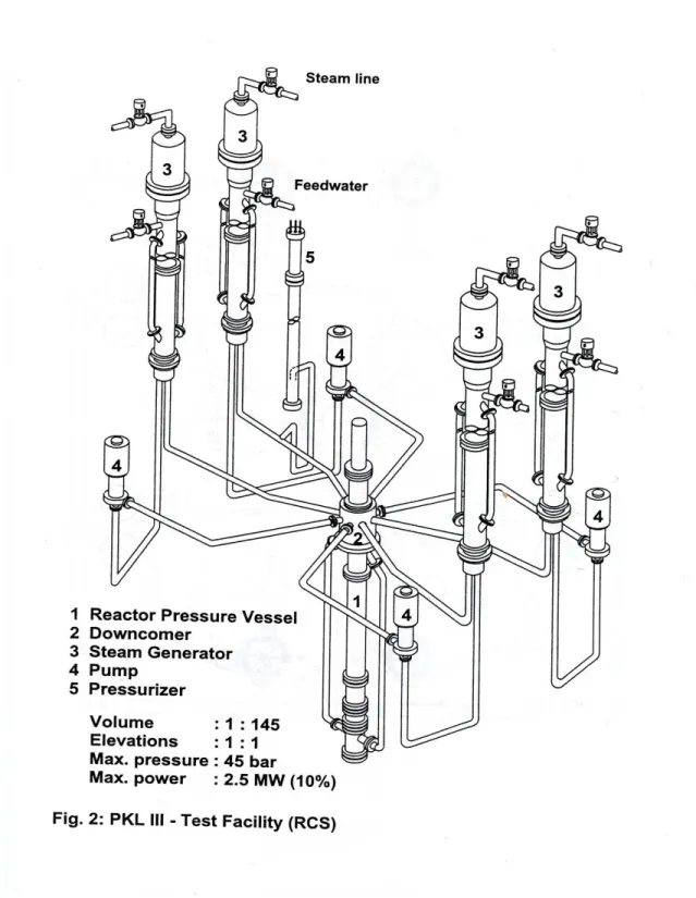
The PKL facility is full high ITF (elevations scaled 1:1), shown in Figure 1 that models the entire primary system and most of the secondary system (except turbine and condenser) of a 1300-MW PWR NPP. It has been used for extensive experimental investigations on the study of the integral behavior of PWR NPP accident conditions (PKL is a German acronym for "Primary System"). Different test programs have been carried out with the PKL facility: PKL I and II test programs (1977 - 1986) focused on LBLOCA and SBLOCA and the PKL III test program (starting from 1986) addressed on the simulation of accident sequences, mainly on the BDBA and the issues related to the day-to-day operation of Siemens-built PWR [1].
The PKL facility has been designed using the specific data of Philippsburg NPP unit 2, and the scaling concepts to simulate overall thermal hydraulic behavior of the full-scale power plant. The following features can be highlighted:
full-scale hydrostatic head;
power, volume, and cross-sectional area scaling factor of 1:145;
full-scale frictional pressure loss for single-phase flow;
simulation of all four loops;
core and SG have full-scale rod and U-tube dimensions, spacers, heat storage capacity but the numbers of rods and tubes are scaled down;
the simulation of phenomena are priority objective compared with the consistent simulation of the geometry, (e.g., in order to account for important phenomena in the hot legs such as flow separation and countercurrent flow limitation – CCFL -, the geometry of the hot legs is based on conservation of the Froude number and was finally designed on the basis of experiments at the full scale UPTF);
the configuration of the RPV DC, modeled as two stand pipes connected to the lower plenum and as an annulus in the upper region, allows the frictional pressure losses preservation and a reasonable volume/surface ratio distortion;
the operating pressure of the PKL facility is limited to 45 bar on the primary side and to 56 bar on the secondary side. This allows simulation over a wide temperature range (250°C to 50°C) that is particularly applicable to the cool-down procedures investigated.
Table 1 gives general information concerning the involved system and support the facility description hereafter. For sake of completeness the data of other PWR test facilities (LOBI, SPES, BETHSY and LSTF) are also reported.
Page 13 of 50 The PKL test facility is subdivided into RCS, SG SS, the interfacing systems on the primary and secondary side and the break.
RCS comprises the vessel, the four loops (pipes, pumps and steam generators), and the pressurizer (PRZ) connected via the surge line to the loop #2.
The vessel models the following:
The upper head plenum is a cylinder, full scale in height and 1:145 in volume. It contains the shaft of the RPV liquid level detector and in the bottom houses the top plate, the upper core support and the control rod guide assemblies.
The upper plenum is full scale in height and scaled down in volume. The internals are simulated by means of seal-welded tube.
The upper head bypass is modeled by four lines associated with the respective loops to enable detection of asymmetric flow phenomena in the RCS (e.g., single-loop operation).
The reactor core model consists of 314 electrically heated fuel rods (diameter 10.75 mm and pitch 14.3 mm) and 26 control rod guide thimbles (diameter 13.6 mm). Three concentric zones can be heated independently and simulate a radially variable power profile. The maximum electrical power of the test bundle is 2512 kW distributed as follows: 504 kW in the inner zone (63 rods with 8 kW each one); 944 kW in the central zone (118 rods with 8 kW each one) and 1064 in the outer zone (133 rods with 8 kW each one). Thermocouples are located in the rod bundle for measuring the rod temperatures.
The reflector gap is between the rod bundle vessel and the bundle wrapper (the barrel in the real plant). Following the reference plant, the flow resistance has been designed in order to have 1% of the total primary side mass flow (with MCP in operation) across the reflector gap. In this zone are also located 2 concentric 1.5 mm thick nickel sheets with the function to protect the rod bundle vessel against overheating (max allowable temperature is 300°C).
The lower plenum contains the 314 extension tubes connected with the heated rods. The down-comer pipes are welded on the lower plenum bottom in diametrically opposite position. Two plates are located in this zone: the Fuel Assembly Bottom Fitting and the Flow Distribution Plate.
The down-comer is modeled as an annulus in the upper region and continues as two stand pipes connected to the lower plenum. This configuration, as already mentioned above, permits symmetrical connection of the 4 CL to the RPV, preserves the frictional pressure losses and does not unacceptably distort the volume/surface ratio. The hydraulic diameter of the down-comer vessel is equal to that of the reactor down-comer. The down-comer pipes simulate the lower portion of the reactor down-comer and the diameter is equal to the hydraulic diameter of the annular down-comer in the prototype reactor.
Page 14 of 50 The facility has four loops; each one is constituted by a hot leg, a U-tube SG (primary side), a loop seal, a main circulation pump and a cold leg. The hot legs have been designed taking into account the relevance of an accurate simulation of the two phase flow phenomena, in particular CCFL, in the hot leg piping as in the reactor. For these reason the hot leg has the scaled diameter in the part flanged to the upper plenum and then a concentric increase from 80.8 mm to 154 mm upstream the connection to the SG inlet plenum. The cold legs connect the SG to the MCP through the loop seal and the MCP to the DC vessel. The hydrostatic elevations of the loop seals are 1:1 compared with the prototype NPP. The cold legs have also nozzles located between thee MCP and the DC vessel for the ECCS injection and two seats in CL 1 and 2 for the break simulation.
The PKL MCP are vertical single-stage centrifugal pumps, driven by variable-speed motors provided with anti-reverse rotation devices.
The PKL PRZ has full height and it is connected through the surge line to the hot leg #2. The electrical heaters and the water spray have been modeled in the water and steam plenum respectively.
The four SG (primary side) of the PKL Test Facility are vertical U-tube bundle heat exchangers like in the prototype NPP. The scaling factor has been preserved by reducing the number of tubes: 28 tubes with outside diameter of 22 mm and wall thickness of 1.2 mm. Seven different lengths are modeled with the shortest and the longest tubes that have the same height of the reactor SG. The SG (secondary side) is constituted by the tube bundle zone where the interface between the RCS and secondary side occurs. Below the shortest tubes, seal welded hollow fillers allow to achieve the correct volumetric scaling of the SG secondary side. The DC model can be divided into three parts: the upper, located above the U-tube zone, is annular and contains the FW ring; the central, in the tube bundle zone, is modeled by two tubes outside of the SG housing; the lower has annular shape formed by a cylindrical shroud within the vessel. The flow distribution plate has been attached to the bottom of the shroud.
The uppermost part of the SG, the larger part of the SG vessel, models the steam plenum. The SG outlet nozzle has a restriction, like the prototype system, in order to reduce the blow-down rate in the MSLB events. Finally the moisture separator, the dryer and the perforate plate of the reactor SG have been simulated with a perforate plate, with appropriate flow resistance, located below the SG outlet nozzle. The condensate, formed in this plate, returns to the SG DC through a funnel place in the uppermost part of the SG below the perforate plate.
Page 15 of 50
Page 16 of 50
Parameters Unit PKL LOBI SPES BETHSY LSTF
Reference reactor or reactor Siemens PWR 4-loop KWU-PWR 4 loops W-PWR 3 loops FRA-PWR 3 loops W-PWR 4 loops Power of the reference reactor or
reactor power
MWth 3765 3900 2775 2775 3423 Reported Kv 1/145 1/712 1/427 1/100 1/48
ITF number of loops 4 2 3 3 2
ITF nominal power MWth 2.512 5.28 6.49 2.86 10.0 ITF volume (with PRZ) m3 3.282(***) 0.648 0.624 2.88 7.952 ITF volume (without PRZ) m3 2.766(***) 0.561 0.5286 2.473 6.805 Primary side fluid total mass (*) (^) kg - 436 423 1984 5404 Pressurizer nominal pressure MPa 4.5 (**) 15.7 15.5 15.5 15.55 Inlet core mass flow rate (^) Kg/s - 3.5 4.25 * 17.5 ** 48.4 Outlet core temperature (^) K - 589 589 588 589 Steam generator secondary side
volume
m3 5.824(***) il 0.7307 Bl 0.1648
1.163 1.952 4.842 4.742 Steam generator secondary side total
mass (^) Kg - Il 325 *** bl 115 182 *** 183 185.5 780.6 *** 2569.5 ***
Secondary side operating pressure MPa 5.6 (**) il 6.94 bl 6.91 6.94 6.80 6.84 6.84 7.0 PS Heat Losses kW 90 (^^) 110 150 54.2 167
* value obtained from figure. ** calculated value.
*** value obtained from pre-test calculations (*) excluding pressurizer
(**) Limit on the operator pressure (***) Reference [2]
(^) This data is referred to the SBLOCA counterpart test (see reference [3]) (^^) Reference [4]
Note : all reported values refer to the experiments mentioned in the bottom line
Page 17 of 50
2.2. Test E2.2 description
The performed test investigates the boron dilution distribution in condition of reduced mass inventory (e.g. SB-LOCA event). The boron dilution takes place when conditions for reflux-condenser phenomenon are established in the plant. This phenomenon produces de-borated water plug in the primary circuit namely in the loop seals. The test OECD-PKL E2.2 [5] has been designed to investigate the boron distribution inside the facility during the asymmetric ECCS injection (HPIS and LPIS in loop 1 and 2) and the following filling up of the facility.
The main relevant aspect of the test is constituted by boron distribution in the facility during the transition between the reflux-condenser conditions to natural circulation conditions particularly paying attention to the low borated slug of water accumulated in the loop seals.
The baseline conditions for test E2.2 (reflux-condenser conditions at high primary-side filling levels with condensate accumulations in the SG inlet channels and in the loop seals) are established in a conditioning phase.
Before the start of the conditioning phase, the test set-up except for the PRZ is completely filled with water with a homogenous boron concentration of 1000 ppm. The heater rod bundle power is 530 kW (decay heat level of 1.8%). At an RCS pressure of 42 bar, the core outlet temperature is 250°C. Heat is removed to the secondary side by sub-cooled natural circulation in all four loops. The main steam generator pressure is 28 bar. After building up the pressure in the secondary side, and having a RCS pressure of 44 bar, the break in cold leg 1 was opened (without feeding into the RCS) initiating TPNC. During this time, the RPV upper head voided rapidly; the PRZ and the SG drained. The main steam pressure is controlled so that the RCS pressure can be held at about 40 bar. However, the transportation of coolant, from the SG inlet side to the outlet side, does not stop up to the time of the fluid levels in the SG outlet dropped below the tube-sheets. At this time the break is closed again. A reflux-condenser condition prevails.
This condition is maintained for a period of time until the loop seals boron concentrations are < 50 ppm. An ECC injection (at a reduced rate) onset into cold legs 1 and 2 occurs even before SOT. Thus, the initial state for test E2.2 is a partially drained reactor coolant system with symmetrical energy removal in the reflux-condenser mode via all four SG at a primary-side pressure of 40 bar. The boron concentration in the loop seals is less than 50 ppm, at the top edge of the core it is about 3600 ppm.
The test is initiated by opening the break (32 cm2/145) in CL 1 between the RCP and the RPV and commencing cool-down of the four SG at 100 K/h. At the same time, the core power is reduced from initially 530 kW (corresponding to a decay heat of 1.8 %) and the injection rates of the SIP on the cold sides of loops 1 and 2 are increased.
Page 18 of 50 The RCS inventory initially drops at SOT: it passes through a minimum at which the SG tubes are completely drained for a time, before climbing again. At RCS pressure < 10 bar the low pressure safety injection (LPSI) pumps are activated and injection occurs (with boron concentration of 2200 ppm) into cold legs 1 and 2. The primary system is refilled. When the RCS pressure rises above 10 bar, the LPSI pumps are switched off. At ~6000 s the SIP are switched off. The test is concluded ~8000 s after SOT.
During refill by cold-side ECC injection, the hot-side coolant present (in the region of the core, the UP and the HL) has to be displaced towards the SG. Since very high boron concentrations are present, particularly in the core region, this displacement process is bound to raise the boron concentration in the components closer to the SG, too. The additional ECC injection accelerated the rise in the filling level. In all SG, the short U-tubes are refilled faster than the longer ones and the steam still being produced and flowing from the core to the SG tubes made the filling level in the SG swell.
In loop 1 with the cold-side break, a slow-moving through flow in forward direction through the SG has already started at time ~3300 s, however the mass flow initially remained below the detection threshold of the mass flow instrumentation. In loop 2, a slow-moving through flow has likewise set in at about the same time, which, however, alternated between forward and backward flow. The onset of circulation occurs in the unfed loops and it affects the boron concentration at the RPV inlet.
Between 4000 s and 5000 s after SOT, quasi-steady-state conditions have been observed in RCS. In 3 loops there is natural circulation, the steam in the RPV upper head is condensing slowly, the filling level in the PRZ is 5 m, and the RCS pressure is about 21 bar.
The boron concentration at the RPV inlet in CL 2 rises. Water with boron concentration of 2500 ppm is already present at the SG outlet and in the SG tubes. The under-borated water originally in loop 2 has been so thoroughly mixed with higher-borated water as a result of the alternating flow processes prevailing in loop 2 that by 6500 s at the latest there are no longer any measurable accumulations of low-borated water present. A similar rise in the boron concentration is also observed in loops 4 and 3. This rise can be explained by the fact that the water that has been in the core region and has been enriched with boron in the reflux-condenser phase is distributed to the hot legs during refill and then displaced further toward the SG, in some cases entering the U-tubes. The resumption of natural circulation then flushed these higher-borated water masses out of the SG and transported them through the loop seals and the cold legs into the RPV.
Page 19 of 50
3. Description of the SPES facility
The SPES (Simulatore PWR per Esperienze di Sicurezza) Integral Test Facility, [6], is designed to simulate the whole primary circuit, the relevant parts of the secondary circuit (steam generator secondary sides, main feed water lines up to the isolation valves, main steam lines upstream the turbine valves), and the most significant auxiliary and emergency systems (charging and let-down system, safety injection system, including high pressure and low pressure system, accumulators, emergency feed water system, steam dump and so on) of the Italian Standard Nuclear power plant (PWR-PUN, Westinghouse 312 type, 3 loops, 2775 MWth core power).
The basic design choices of the facility are the following:
three active loops to simulate a three loops reactor;
design pressure 20 MPa, design temperature 910 K; this choice allows the execution of tests with primary pressure over the reactor design pressure (17.2 MPa);
electrical heating of the power channel: 97 electrically heated rods, with uniform flux (local hot spots can be simulated by means of three rods with a peaking factor of 1.19);
maximum channel power corresponding to about 140% of the reactor nominal power; this choice allows the simulation of reactor power excursions;
volume scaling factor and power scaling factor (nominal power about 6.5 MW) equal to 1:427;
height of all the components is the same as in real plant, except for the pressurizer which is shorter, in order to preserve the volume scaling ratio and to maintain at the same time an acceptable flow area.
A sketch of the primary and secondary loops is reported in Figure 2.
In the SPES rig 375 measurement points are available, providing a large set of both direct physical quantities (absolute and differential pressure, temperature, voltage, etc.) and derived physical quantities (void fraction, mass velocity, quality, etc.).
Various kinds of transducers are located in the SPES facility (thermocouples, heated thermocouples, pressure transmitters, differential pressure transmitters, densitometers, void fraction probes, Venturi tubes, turbines, catch tank), supplying the following parameters:
temperature pressure differential pressure liquid level density void fraction
Page 20 of 50
velocity
flow pattern
fluid mass
Page 21 of 50
4. Adopted code and nodalization
4.1. RELAP5/Mod3.3 code
The light water reactor transient analysis code, RELAP5, was developed at the Idaho National Engineering Laboratory (INEL) for the U.S. Nuclear Regulatory Commission (NRC). Specific applications of the code have included simulations of transients in LWR system such as loss of coolant, anticipated transients without Scram (ATWS) and operational transients, such as loss of feed water, loss of offsite power, station blackout and turbine trip.
The Mod3 version of RELAP5 has been developed jointly by the NRC and a consortium consisted of several countries and domestic organizations that were members of the International Code Assessment and Application Program (ICAP) and its successor organization, Code Application and Maintenance Program (CAMP).
RELAP5/Mod3.3 code, [7], is based on a non-homogeneous, non-equilibrium set of six partial derivative balance equations for the steam and the liquid phase. A non-condensable component in the steam phase and a non-volatile component (boron) in the liquid phase can be treated by the code. A fast, partially implicit numeric scheme is used to solve the equations inside control volumes connected by junctions.
In particular, the control volume has a direction associated with it that is positive from the inlet to the outlet. The fluid scalar properties, such as pressure, energy, density and void fraction, are represented by the average fluid condition and are viewed as being located at the control volume center. The fluid vector properties, i.e. velocities, are located at the junctions and are associated with mass and energy flow between control volumes. Control volumes are connected in series using junctions to represents flow paths.
Heat flow paths are also modeled in a one-dimensional sense, using a staggered mesh to calculate temperatures and heat flux vectors. The heat structure is thermally connected to the hydrodynamic control volumes through heat flux that is calculated using a boiling heat transfer formulation. The heat structures are used to simulate pipe walls, heater elements, nuclear fuel pills and heat exchanger surfaces.
Two limits have fixed for the linear dimensions of nodes: all the volumes should have their flow lengths comprised between 0.5 and 1.0 m (with the exception of core stack, much more detailed, of the descending zone of the SG U-tubes and of the pressurizer and accumulator surge line, nodalized by 2.0 m length nodes). With regard to conduction heat transfer, the distance between neighboring mesh points inside structures must be less than 5 mm in each case, up to the lower limit of few tenths of mm used for heated rods and steam generator U-tubes. In the subdivision of volumes and slabs the position of instrumentation has been considered.
Page 22 of 50
4.2. SPES nodalization description
For the present study the nodalization of SPES facility has been adopted which has been previously applied and qualified for the simulation of test SP-SB-04 performed at SPES facility [8].
The RELAP5/Mod3 nodalization for the SPES facility is shown in Figure 3. The correspondence between the zones of the facility and the nodes of the code model is presented in Table 2 and Table 3. In this table the facility is divided in zones, composed by various hydraulic elements. These components are reported in the table according to flow paths in nominal conditions. Number and type of the hydraulic nodes are indicated in the table itself.
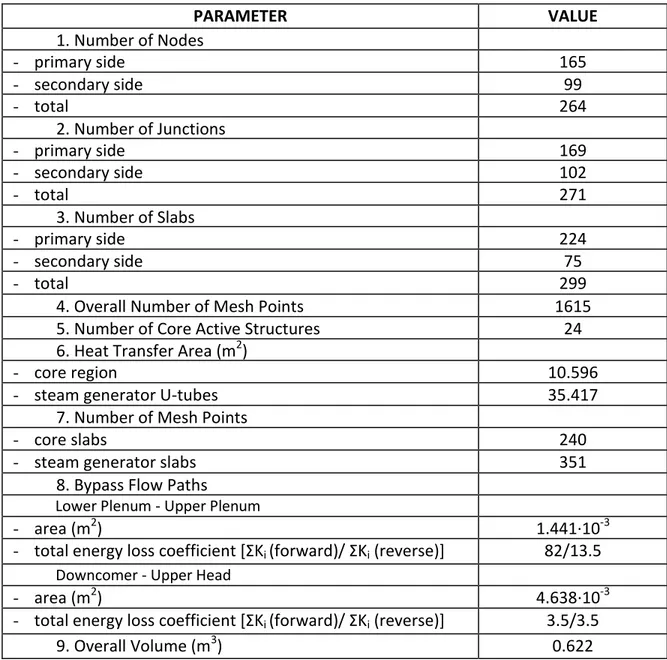
The utilized code resources for the SPES nodalization are summarized in Table 4. In particular, the numbers of hydraulic components and of heat structure are reported.
Hereafter some significant aspects of the developed nodalization are summarized.
The vessel model consists of 45 hydraulic components which are connected through 48 junctions. The heat structures used in the vessel model are made up of 78 heat slabs subdivided in:
24 active structures for the heaters exchanging heat with the pipe component 130 (composed by 12 volumes), where the overall power is dissipated: two stacks of 12 slabs simulate the three hot rods and the remaining 94 rods of the core bundle;
4 internal non-active structures simulate the connection zones (in the lower part and in the upper part of the bundle) exchanging heat with the branch components 100-01, 110-01, 120-01 and 140-01, where no power is assumed to be dissipated;
50 heat slabs simulate the vessel structures; in 19 over 50 slabs the heat exchange with the environment is imposed.
In the vessel model all the bypass flow paths reported in the facility description have been modeled:
bypass from lower plenum to upper plenum simulated by the pipe components 112 and 114 connected through the single junction 113;
bypass from downcomer top to upper head simulated by the pipe component 145 and the single junction 155.
The three loops are almost equal in the nodalization (33 volumes, 32 junctions and 42 slabs) and are differentiated for the pressurizer (placed in loop 2). For simplicity the loop 3 is not shown in Figure 3, it has the same features of the loop 1.
The steam generator U-tubes are modeled asymmetrically, assuming that the largest portion of the exchanged power between primary and secondary side occurs across the slabs of the rising part of the package.
Page 23 of 50 The pumps in the three loops are considered equal; different working conditions are achieved by changing the shaft velocity. The related input two phase curve differences, which for completeness have been considered in the nodalization, have been set equal to ones related to the LOBI/Mod2 pumps.
Two additional systems can be noted in the pressurizer nodalization:
a time dependent volume and related trip valve (component 60-01 and 65-01 respectively);
a time dependent junction and related time dependent volume (components 45-01 and 40-01 respectively).
Both are control systems. The former system allows the primary side pressure to remain constant in the steady-state period. The latter system maintains at an assigned value the liquid level inside the pressurizer. The temperature of the fluid possibly injected by this system corresponds to the saturation conditions inside the pressurizer.
Still, the block structures inside the pressurizer model represent the internal heaters; they simulate in the code model also the external heaters installed in the facility. The motor valve 75 and the related time dependent volume 70-01, connected to the top of the pressurizer, simulate the PORV system.
The secondary side nodalization of the three steam generators are equal both concerning the hardware of the facility and the control systems (33 nodes, 34 junctions and 25 head slabs): in particular the volume identification number can be obtained by changing the first digit in the loop 1 related one (6 in place of 5 for loop 2 and 7 for loop 3). Thus, only one nodalization will be described hereafter. Five zones can be recognized in each steam generator:
the downcomer, consisting of a single stack of nodes (the two external downcomers are gathered in a single pipe component);
the riser zone, essentially including the U-tubes;
the top of the vessel, including the separator, the dryer and the steam dome regions;
the steam line downstream the dome of each SG, simulated with the pipe component 525-01, the motor valve 580 and the time dependent volume 581. This last component is also utilized like a pressure control volume imposing constant pressure in the volume itself;
the feedwater line connected to the top the downcomer, simulated with the pipe component 565-01, the time dependent junction 591 and the time dependent volume 590.
Page 24 of 50
GENERAL ZONE NAME NUMBER TYPE
PRESSURE VESSEL DOWNCOMER REGION 135 BRANCH 125 BRANCH 115 PIPE 105 BRANCH
LOWER PLENUM 100 BRANCH
110 BRANCH 120 BRANCH
LP-UP BYPASS 112 PIPE
113 SNGLJUN 114 PIPE
CORE REGION 130 PIPE
140 BRANCH
UPPER PLENUM 150 BRANCH
160 BRANCH
UPPER HEAD 170 BRANCH
180 BRANCH 190 PIPE DC-UH BYPASS 155 SNGLJUN
145 PIPE LOOP 1
(LOOP 2) [LOOP 3] PIPING
VESSEL NOZZLE 200 (300) [400] BRANCH HOTLEG 210 (310) [410] BRANCH SG INLET PIPE 220 (320) [420] PIPE SG INLET JUNCTION 225 (325) [425] SNGLJUN SG OUTLET JUNCTION 235(335)[435] SNGLJUN SG OUTLET PIPE 240 (340) [440] PIPE LOOP 250 (350) [450] BRANCH
260 (360) [460] PIPE PRIM. COOLANT PUMP 270 (370) [470] PUMP
COLD LEG 280 (380) [480] BRANCH 290 (390) [490] BRANCH
PRESSURIZER SURGE LINE 010 PIPE
PRESSURIZER VESSEL 015 BRANCH 020 BRANCH 025 PIPE 030 BRANCH 035 BRANCH PRZ LEVEL CONTROLSYSTEM 045 TMDPJUN 040 TMDPVOL PRZ PRESSURE CONTROL SYSTEM 065 TRPVLV 060 TMDPVOL PORV 075 MTRVLV 070 TMDPVOL PRESSURIZER LEAK 085 TMDPJUN 080 TMDPVOL
Page 25 of 50
GENERAL ZONE NAME NUMBER TYPE
SG1 (2) [3] SECONDARY SIDE
U -TUBE 230 (330) [430] PIPE RISER 500 (600) [700] PIPE UPPER PLENUM 505 (605) [705] BRANCH SEPARATORS 510 (610) [710] SEPARATR STEAM DOME 520 (620) [700] BRANCH DOWNCOMER 530 (630) [730] BRANCH 540 (640) [700] BRANCH 560 (660) [760] BRANCH 570 (670) [770] PIPE DC-RISER CONNECTION 575 (675) [775] SNGLJUN FEEDWATER LINE 590 (690) [790] TMDPVOL
591 (691) [791] TMDPJUN 565 (665) [765] PIPE EFW SYSTEM 592 (692) [792] TMDPVOL
593 (693) [793] TMDPJUN TRANSIENT STEAM
LINE
(PRE. CONTR. SYSTEM)
581 (681) [781] TMDPVOL
580 (680) [780] MTRVLV 525 (625) [725] PIPE STEADY - STATE STEAM LINE 582 (682) [782] TMDPJUN
583 (683) [783] TMDPVOL LEVEL CONTROL SYSTEM 594 (694) [794] TMDPVOL 595 (695) [795] TMDPJUN 596 (696) [796] TMDPVOL 597 (697) [797] TMDPJUN SAFETY RELIEF VALVE 585 (685) [785] TMDPVOL 584 (684) [784] MTRVLV SG LEAK 586 (686) [7861 TMDPVOL
587 (687) [787] MTRVLV
BREAK BREAK VALVE (383) TRPVLV
BREAK VOLUME (384) TMDPVOL LPIS LPIS JUNCTION 278 [478] TMDPJUN LPIS TANK 277 [477] TMDPVOL
ACCUMULATOR
ACCUMULATOR VALVE 281 [481] MTRVLV
ACCUMULATOR INJ LINE 282 [482] PIPE
ACCUMULATOR 284 [484] ACC
Page 26 of 50 PARAMETER VALUE 1. Number of Nodes - primary side 165 - secondary side 99 - total 264 2. Number of Junctions - primary side 169 - secondary side 102 - total 271 3. Number of Slabs - primary side 224 - secondary side 75 - total 299
4. Overall Number of Mesh Points 1615 5. Number of Core Active Structures 24 6. Heat Transfer Area (m2)
- core region 10.596
- steam generator U-tubes 35.417
7. Number of Mesh Points
- core slabs 240
- steam generator slabs 351
8. Bypass Flow Paths
Lower Plenum - Upper Plenum
- area (m2) 1.441∙10-3
- total energy loss coefficient [ΣKi (forward)/ ΣKi (reverse)] 82/13.5
Downcomer - Upper Head
- area (m2) 4.638∙10-3
- total energy loss coefficient [ΣKi (forward)/ ΣKi (reverse)] 3.5/3.5
9. Overall Volume (m3) 0.622
Page 27 of 50
Page 28 of 50 The degree of detail of the nodalization is commensurate to what considered in the primary loop. In particular, the heights of the riser volumes are the same as the minimum between the heights of the rising and descending corresponding nodes of the primary side U-tubes.
The component 510-01 simulates the separator that is necessary in the code model in order to achieve quality equal to one in the steam dome.
The pre-heaters are not simulated in the code model.
A relatively large number of control volumes are connected with the steam generators; the following functions are accomplished:
feedwater injection and steam line previously described;
EFW injection: simulated with the time dependent volume 592 and with the time dependent junction 593 (used only in the steam generator of the loop 1);
SRV safety system: simulated with the time dependent volume 585 (safety tank) and with the motor valve 584 (safety valve);
liquid level control system: realized through two time dependent volume components (596 and 594), each one connected with one time dependent junction (597 and 595 respectively). This system assures constant value for steam generator downcomer liquid level during the steady-state period.
Page 29 of 50
5. SPES test description and objectives
5.1. Conditioning phase
The objective of the conditioning phase to be performed at SPES facility is to obtain conditions corresponding to the SOT of test E2.2 of PKL: partially drained primary side with energy removal in the reflux-condenser mode at a primary-side pressure of 40.5 bar and condensate accumulations in the loop seals. The parameters describing the SOT state to be achieved are provided in the Table 5. The proposed conditions in SPES prior to start of conditioning phase are the completely filled primary side at nominal pressure, reduced core power, low-flow in the loops (at reduced main circulating pumps velocity) and low pressure at the secondary side. Facility initial conditions are presented in the Table 6.
In order to reach the conditions of SOT, a 4.156 mm2 break is opened in the CL of loop 2. After the primary pressure reaches 13 MPa setpoint, the scram is activated, thus reducing the core power to the decay heat level of 95.6 kW, and the MCP are tripped and followed by a short coastdown. Once the primary side mass inventory is reduced to 50% of its initial value, the break is closed and the facility is let to operate in reflux-condenser mode, building up the condensate in the loop seals. Once the boron concentration in the loop seals reached 50 ppm, the SOT is considered to be achieved and the conditioning phase is terminated. During entire conditioning phase the secondary side pressure and levels in SG are maintained constant. No ECC systems are put into operation. The boundary conditions are listed in Table 7.
# CONDITION VALUE NOTE
1 U-Tubes filled with steam reflux condenser conditions
2 Coolant inventory 50 %
3 Boron concentration < 50 ppm in LS > 4000 ppm in core outlet
4 Core power 95.6 kW
5 Primary side pressure 40.5 bar 6 Coolant temperature at core outlet 251 °C 7 Subcooling at core inlet 0 °C
8 Flow rate in loops - No circulation in all the loops MCP stopped 9 Main steam pressure in SG secondary side 39.0 bar maintained constant 10 Main steam temperature in SG secondary side 249 °C
11 Collapsed level in SG secondary side 11.5 m maintained constant
Page 30 of 50
# CONDITION VALUE NOTE
1 Core power 768 kW reduced with respect to nominal 2 Primary side pressure 152 bar
3 Coolant temperature at reactor inlet 243 °C 4 Coolant temperature at reactor outlet 284 °C 5 Boron concentration 1000 ppm 6 Flow rate in loops 1.75 kg/s
7 MCP velocity 389 rpm reduced with respect to nominal
8 Pressurizer level 3.15 m
9 Main steam pressure in SG secondary side 39 bar 10 Collapsed level in SG secondary side 11.5 m 11 Feedwater temperature 164 °C
Table 6. SPES initial conditions prior to conditioning phase
# CONDITION VALUE NOTE
1 Break Area 4.156 mm2 CL loop 2
2 SCRAM occurrence PS pressure < 13 MPa setpoint 3 MCP trip PS pressure < 13 MPa setpoint 4 Break closure PS Mass < 50% setpoint 4 HPSI/LPSI/Accumulators intervention NO
5 Secondary side pressure 39 bar maintained constant
Page 31 of 50
5.2. Test phase
Once the SOT conditions are achieved, the test phase procedure is started by
reopening of the break in the CL of loop 2 (4.156 mm2);
start of 100 K/h cooldown of all 3 SG-secondaries;
start of the core power decrease (see below for details);
start of HPSI injection into CL loop 1 (with boron concentration of 2200 ppm). Further measures taken throughout the test are:
start of LPSI to inject water (with boron concentration of 2200 ppm) into cold leg of loop 1 when primary side pressure is below 10 bar;
stop of the HPSI at a secondary pressure lower than 2 bar.
The list of boundary conditions for the test phase is provided in the Table 8.
The secondary side pressure at cooldown measured in PKL facility has been applied as a boundary condition for the test phase in SPES facility (Figure 4). Core power, HPSI and LPSI injection rates measured in PKL facility has been scaled following the power-to-volume scaling approach [9], using the ratio of facilities volumes Kv as a scaling factor, and applied to the SPES test phase (Figure 5,
Figure 6 and Figure 7).
# CONDITION VALUE NOTE
1 Break Area 4.156 mm2 CL loop 2
2 Secondary side pressure 100 K/h cooldown PKL values applied. Figure 4 3 Core power decay curve PKL values scaled and applied. Figure 5 4 HPSI intervention start at SOT PKL values scaled and applied. Figure 6 4 LPSI intervention at PS pressure < 10 bar PKL values scaled and applied. Figure 7 5 SG collapsed level 11.5 m maintained constant
6 End of transient 7500 s
Page 32 of 50
Figure 4. Test phase secondary side pressure
Page 33 of 50
Figure 6. Test phase HPSI injection flowrate
Page 34 of 50
6. Analysis of calculation results
6.1. Conditioning phase
Before commencing the calculation of conditioning phase, a steady-state has been achieved by running a ‘null transient’ of 100 s with parameters specified in Table 6. SPES initial conditions prior to conditioning phase. The model parameters were stable, i.e. solutions are stable with an inherent drift < 1% / 100 s.
The break has been opened at -3300 s (the reference time 0.0 s has been assigned to SOT instant). The facility experienced an expected depressurization (Figure 8) which triggered the SCRAM and MCP trip at -3253 s. The PRZ is drained within 100 s after the opening of the break (Figure 9). The primary pressure continued to decrease until it is leveled with the constantly maintained secondary side pressure (Figure 10).
After the end of imposed MCP coastdown at -3240 s, the hot leg started to void, indicating the transition to the two-phase natural circulation in the loops which lasted until -2600 s. From that moment until the SOT the facility has been in the state of reflux-condenser mode with gradual build-up of deborated condensate in the loop seals.
At -2250 s the SG U-tubes are completely emptied, The break has been closed at -2175 s (1125 s after the start of conditioning phase) once the primary side mass decreased to 50% of its initial value (Figure 13).
Being in the reflux-condenser mode and, thus, building-up the condensate in the loop seals the boron concentration reaches 50 ppm by the time 0 s (Figure 14). The conditions of the SOT (Table 5) are met at the conditioning phase considered terminated.
It should be noted that although the obtained core inlet temperature matches the objective for SOT (0 °C subcooling), the fluid temperature at the inlet to the downcomer are rather low comparing to the PKL results. This may be caused by the effect that at stagnant conditions the fluid is overcooled by the overestimated/uncompensated heat losses. In the present study this is of no importance, although a detailed analysis of heat losses may be performed during the experiment technical specification program.
During the conditioning phase no dryout conditions and no increase of the heater rod temperature were observed in the core region.
Page 35 of 50
Figure 8. Conditioning phase: Primary side pressure
Page 36 of 50
Figure 10. Conditioning phase: Primary side and secondary side pressure
Page 37 of 50
Figure 12. Conditioning phase: Pressure drop across U-tubes loops 1 and 2
Page 38 of 50
Figure 14. Conditioning phase: Boron concentration at loop seal bottom
Page 39 of 50
6.2. Test phase
After the SOT conditions have been reached, the test phase is commenced by reopening the break in the cold leg of loop 2. The other boundary conditions have been implemented in the input deck using the following approach:
Cooldown pressure curve (Figure 4) has been imposed at the outlet from SG by means of
time-dependent volume component;
The power trend (Figure 5) has been supplied in a form of tabular data;
HPSI injection has been imposed as a mass flow rate through the time-dependent junction component in the loop 1 and has started from the time 0 s;
LPSI injection has been imposed as a mass flow rate through the time-dependent junction component in the loop 1 with the onset of injection at primary pressure < 10 bar, which has effectively started at 2690 s;
After the opening of the break the primary side pressure started to decrease, following the cooldown curve of the secondary side, thus remaining coupled (Figure 16). The primary side continued to lose its mass inventory until it reached its minimum value 42% at 570 s (Figure 17). From then on, the primary mass was being recovered by ECC injection until the stop of HPSI at 5980 s.
The refill of the system led to the partial refill of the pressurizer (Figure 18) that caused the increase in primary pressure. As the ECC injection stopped, the PRZ emptied again and the primary pressure aligned with the secondary side pressure again.
The gradual recovery of the primary mass inventory led to the refill of SG U-tubes which was completed by 3600 s (Figure 19) and allowed the restart of the natural circulation in the loops at 3900 s (Figure 20). It should be noted that after the stop of ECC injection at 5980 s the natural circulation in broken loop 2 has ceased.
After the start of HPSI injection at 0 s into the CL loop 1 the boron concentration in the loops 1 and 2 started to increase - gradually in the loop seal (Figure 21) and sharply in the cold leg (Figure 22): in loop 1 due to the injected water and in loop 2 due to the reverse flow in the cold leg caused by open break. The unfed loop 3 shortly after the start of the test phase experiences the loop seal clearance and remains empty from 650 s until 1920 s. After the refill of this loop, the boron concentration in this loop levels up with the other loops at about 2000 ppm. The boron concentration in the lower plenum and lower part of the core inside the power channel increases initially after start of the test phase: partially due to the water delivery by HPSI and partially due to the reverse flow of the highly-borated water from top part of the core and hot legs.
The test phase considered terminated at 7000 s with refilled facility at natural circulation conditions and average boron concentration 2200 ppm and secondary side pressure about 1.4 bar.
Page 40 of 50
Figure 16. Test phase: Primary side and secondary side pressure
Page 41 of 50
Figure 18. Test phase: Pressurizer level
Page 42 of 50
Figure 20. Test phase: Mass flowrate in the loops at the SG outlet
Page 43 of 50
Figure 22. Test phase: Boron concentration in cold legs
Page 44 of 50
Page 45 of 50
7. Requirements to facility measurement system
Apart from the typical measurement system of an ITF which is already available at SPES facility, certain specific requirements are posed for the current experimental test:
boron concentration measurements;
mass flow and flow direction measurements;
pressure drop measurements.
The instrumentation for the boron measurements is required of two different types: 1. the COMBO (Continuous Measurement of Boron Concentration) devices or similar; 2. sampling points.
The COMBO (Continuous Measurement of Boron Concentration) devices are suitable for the continuously measuring of the boron concentration and they are operating according to the principle of neutron absorption. The COMBO system was originally developed by Siemens (now Framatome-ANP) for use in real PWR. The measuring principle is based on the absorption of neutrons by the isotope B-10, which varies according to the boron content of the coolant. The COMBO system, which basically consists of a neutron source (positioned on one side of the reactor coolant line - RCL) and two counter tubes (installed close together on the opposite side of the RCL) can be mounted on the outer wall of the RCL so that it has no effect on the fluid being measured. A scheme of the COMBO device arrangement is reported in Figure 25. The result of using this neutron transmission method is a measurement averaging over the entire flow cross section in the pipe.
The test facility has to be also retrofitted with sampling points for taking grab samples at several locations in the primary system, such as in the loop seals, in the steam generator inlet and outlet plena, in the downcomer and in the region of the core.
Page 46 of 50 The proposed locations for the installation of boron measurement devices are the following:
COMBO devices
o Cold legs at the inlet to the downcomer (trends of Figure 22substantiate the present proposal)
Sampling o Hot legs
o Loop seal descending leg o Loop seal bottom
o Loop seal ascending leg o Downcomer top
o Downcomer bottom o Core bottom
o Core top
Due to high cost of the COMBO devices, it has been investigated the possibility to perform the measurement of boron concentration by electrical conductivity probes to be installed at the SPES facility. The electrical conductivity measurements performed with those probes are intended to detect the arrival of the injected boric acid solution at specified key locations and thus indirectly provide a precise quantification of the overall boron affecting the selected transient, which can be exactly defined only experimentally. Conductivity probes can be used in the SPES facility to measure the conductivity of the water (which is altered by the presence of boric acid) and then to obtain the boric acid concentration as a function of time during the experiment. In this way they allow to detect the passage of the solution and to measure the injection time sequence, defined as the span time between the starting of the typical considered event and the entrance of the first infinitesimal volume of boron into the moderator tank.
The proposed conductivity sensors are custom-made needle probes designed and manufactured according to the following technical specification:
Measurements of local electrical conductivity in water (maximum conductivity 40 µS/cm) for operation with 10 kHz fast conductivity signal sampling electronics;
Coaxial electrode design;
Temperature range: 5 °C to 80 °C;
Maximum static differential pressure between probe head and probe body: 12 MPa;
Probe shaft diameter: 10 mm.
The selected probe is supported by a steel tube mounted onto a tank replacing the moderator by a Swagelok-type fitting, which in turn will be screwed on the tank, Figure 26. Owing to the adoption of Swagelok connections, each probe can be inserted into the tank to the needed extent. The
Page 47 of 50 correct positioning of the conductivity probes has to be specified in terms of axial and radial positioning: the criterion is that the probe tip must be positioned so as to be able to fully intercept the tracer, Figure 27.
The proposed locations for the installation of flow measurement devices are the following:
Mass flow rate measurement
o SG outlet / loop seal descending leg
Flow direction detection o Loop seal bottom
Pressure drop measurement devices must be sufficiently installed in order to provide detailed information on the fluid distribution along the primary system.
Page 48 of 50
Page 49 of 50
8. Conclusions
The feasibility study of a boron dilution distribution test in condition of reduced mass inventory (e.g. SB-LOCA event) in the SPES experimental facility has been performed. The conditions of the analysed test have been selected to constitute the counterpart to test E2.2 performed at PKL facility.
The test initiates with a partially drained reactor coolant system with symmetrical energy removal in the reflux-condenser mode via all SG at a primary-side pressure of 40 bar and boron concentration in the loop seals less than 50 ppm. In order to predict the SPES performance during the proposed test, the system thermal-hydraulic computer code RELAP5/Mod3.3 has been used and a nodalization for the SPES facility has been updated, starting from an input previously developed, qualified and applied by University if Pisa for simulation and analysis of the experimental test SP-SB-04. Two phases of boron dilution distribution test have been simulated:
Conditioning phase, required to achieve the conditions of the facility corresponding to the “start-of-test” state;
Test phase, actually simulating the facility refill and boron re-distribution in the facility under conditions of asymmetric ECC injection.
It has been demonstrated that it is feasible to achieve SOT conditions in SPES in about 3300 s, starting from full-pressure low-power low-flow conditions in the primary side, by opening the break in the CL loop 2, closing it when the primary mass inventory decreases to 50% and operating in reflux-condenser mode conditions until the boron concentration in loop seals reaches 50 ppm. In order to constitute a counterpart to test E2.2 in PKL facility, the boundary conditions for the test phase in SPES facility have been derived from PKL experimental measured data following the power-to-volume scaling approach: the PKL secondary side pressure has been imposed at the outlet from SG in SPES nodalization; break area, power, HPSI and LPSI mass flow rates have been scaled down using the ratio of primary side volume of two facilities.
The calculation results demonstrated that the main thermal-hydraulic aspects, which have been observed in the test E2.2 at PKL facility, are present in the test phase in SPES facility: reflux-condenser mode, facility refill by ECC system intervention, natural circulation in all loops during asymmetric ECC injection and change of boron distribution in the facility. Thus, it may be concluded that boron dilution distribution test is feasible in SPES facility, with the boundary conditions specified.
In addition, some requirements for the SPES measurement system have been identified: the facility must be equipped with boron concentration and mass flow rate measurement devices in order to conduct the experimental test and provide meaningful information for the subsequent analysis.
Page 50 of 50
References
[1] D’Auria F., Galassi G.M., “Code assessment methodology and results”, IAEA Technical Workshop/Committee on Computer Aided Safety Analyses, Moscow, May 14-17, 1990
[2] H. Kremin, et al.; “Determination of Individual Volumes and of Total Volume in the PKL Test
Facility”; FANP NT31/01/e33, Technical Centre of FRAMATOME-ANP Erlangen, Germany,
August 2001
[3] F. D’Auria, et al.; “Evaluation of the Data Base from High Power and Low Power Small Break
LOCA Counterpart Tests Performed in LOBI, SPES, BETHSY and LSTF Facilities”; Università di
Pisa, DCMN NT 237 (94), Pisa, November 1994
[4] H. Kremin, et al.; “Determination of Thermal Losses in the PKL Test Facility”; FANP NT31/01/e36, Technical Centre of FRAMATOME-ANP Erlangen, Germany, September 2001 [5] OECD/SETH: PKL III E2.2, CD-ROM, FRAMATOME-ANP GmbH TGT1, 11 November 2002
[6] Bolognini C, Gandolfi S., Medich C, Rigamonti M., Vescovi O., Visconti G., Boiardi A., “Experimental data report - SPES test SP-SB-04”, SIET, Sviluppo e Qualifica di Componenti Termomeccanici, Piacenza (ITALY), March 1992.
[7] “RELAP5/Mod3.3 Code Manual Volume I: Code structure, system models, and solution methods”, NUREG/CR-5535/Rev P3-Vol I, Information Systems Laboratories, Inc., Idaho Falls, March 2003
[8] F. D’Auria, M. Frogheri, W. Gianotti “RELAP5/MOD3.2 Post Test Analysis and Accuracy
Quantification of SPES Test SP-SB-03(04)”, NUREG/IA-0154(55), February 1999
[9] D’Auria F., Galassi G.M. “Scaling in nuclear reactor system thermal-hydraulics” Nuclear Engineering and Design Volume 240, Issue 10, October 2010, Pages 3267-3293