Stefano Niccolai
Evalutation of Two
Different Schemes for
Subscriptions and
Notifications Dissemination in
a Component-Based
Publish/Subscribe System for
WSNs
Tesi di Laurea Specialistica
Universit´
a di Pisa
Facolt´a di Ingegneria
Corso di Laurea Specialistica in Ingegneria Informatica
Evalutation of Two Different Schemes for
Subscriptions and Notifications
Dissemination in a Component-Based
Publish/Subscribe System for WSNs
Tesi di
Stefano Niccolai
Relatori:
Prof. Marco Avvenuti
. . . .
Ing. Alessio Vecchio
. . . .
Candidato:
Contents
1 Introduction 1
1.1 Wireless Sensor Networks . . . 1
1.2 Publish-Subscribe . . . 2
1.3 Goals . . . 4
2 The Publish-Subscribe in WSN 7 2.1 Model definition . . . 7
2.2 Content-Based Publish-Subscribe: a TinyOS implementation . 9 3 Communication Protocols 15 3.1 Drain . . . 15
3.1.1 Building a routing tree . . . 15
3.1.2 Using the tree . . . 16
3.2 Broadcast . . . 17
3.3 Drip . . . 18
3.3.1 Trickle algorithm . . . 19
3.3.2 Drip as a Trickle implementation . . . 21
3.4 Passive Clustering . . . 22
4 Passive-Clustering Implementation 25 4.1 TinyOS and nesC Language . . . 25
4.2 Protocol Functional Description . . . 27
4.3 Implementation Overview . . . 31
4.4 Component Detailed Description . . . 32
4.4.1 GenericQueueM . . . 32
4.4.2 PassiveClusteringM . . . 35
4.4.3 OrdinaryWrapperM and InitialWrapperM . . . 37
4.4.4 GatewayWrapperM . . . 37 v
4.4.5 ClusterHeadWrapperM . . . 37
4.5 Detailed Procedures Description . . . 41
4.5.1 Sending a packet . . . 41
4.5.2 Receiving a packet . . . 44
4.5.3 Queue Management . . . 45
5 Simulation Setup 47 5.1 TOSSIM Simulator . . . 47
5.2 The Simulated Configurations . . . 50
5.3 Load Model . . . 53 5.4 Model Validation . . . 55 6 Simulations 59 6.1 Metrics . . . 59 6.2 Simulation Scenarios . . . 61 6.3 Results . . . 61 6.3.1 General Properties . . . 63
6.3.2 Effects of traffic load . . . 70
6.3.3 Effects of topology . . . 71 6.4 Final Reflections . . . 73 7 Conclusions 79 A TOSSIM multiplatform 85 B CC2420 Modifications 89 B.1 Acknowledgments issue . . . 89 B.2 Concurrent Transmissions . . . 91 vi
List of Figures
1.1 General Architecture of a Publish-Subscribe System . . . 3
2.1 Component Scheme of the TinyOS PS Middleware . . . 12
2.2 Subscription Message Format . . . 13
2.3 Notification Message Format . . . 13
3.1 Beacon Message Format . . . 16
3.2 Multiple Sources Problem in Broadcast Protocol . . . 17
3.3 Short-Listen Problem in Drip Protocol . . . 20
3.4 Drip Message Format . . . 21
4.1 Complete PC Message Format . . . 27
4.2 State Transition Updating Queues . . . 29
4.3 State Transition on Packet Transmission . . . 30
4.4 The AM Stack Modified . . . 32
4.5 The General Architecture of PassiveClusteringC Component . 33 4.6 Queue Updating Flowchart . . . 45
5.1 TOSSIM Architecture . . . 48
5.2 Application Configurations . . . 51
5.3 Simulated Publish-Subscribe System . . . 54
5.4 Subscription Process . . . 54
5.5 PC Validation Test . . . 57
6.1 Broadcast Activity . . . 63
6.2 CDF for Broadcast Operation needed by a subscription injection 64 6.3 CDF for Subscriptions Diffusion Delay . . . 66
6.5 Number of Broadcast Transmissions and State Changes for a
100 motes scenario . . . 68
6.6 CDF for Notifications Delay . . . 69
6.7 CDF for Notifications Delivery Ratio . . . 70
6.8 Broadcast messages needed to disseminate subscription . . . . 71
6.9 Per-mote Average Delay for Subscriptions Diffusion . . . 72
6.10 Notifications metrics for different traffic loads . . . 72
6.11 Broadcasts needed to complete subscriptions diffusion . . . 74
6.12 Per-Mote Subscriptions Delivery Ratio . . . 74
6.13 CDF of Notifications Delivery Ratio - Variable Density . . . . 75
6.14 Broadcasts needed to complete subscriptions diffusion . . . 75
A.1 TOSSIM Communication Mechanism . . . 86
List of Tables
3.1 Trickle Pseudo-Code . . . 20
4.1 Passive Clustering Internal and External State . . . 28
4.2 GenericQueue Interface . . . 34
4.3 GatewayEntry and NeighborEntry Type Definition . . . 35
4.4 PassiveClusteringM Definition . . . 36
4.5 RecalculateMemebers Function . . . 38
4.6 Process Gateway Output Method . . . 39
4.7 Neighbor Interface . . . 39
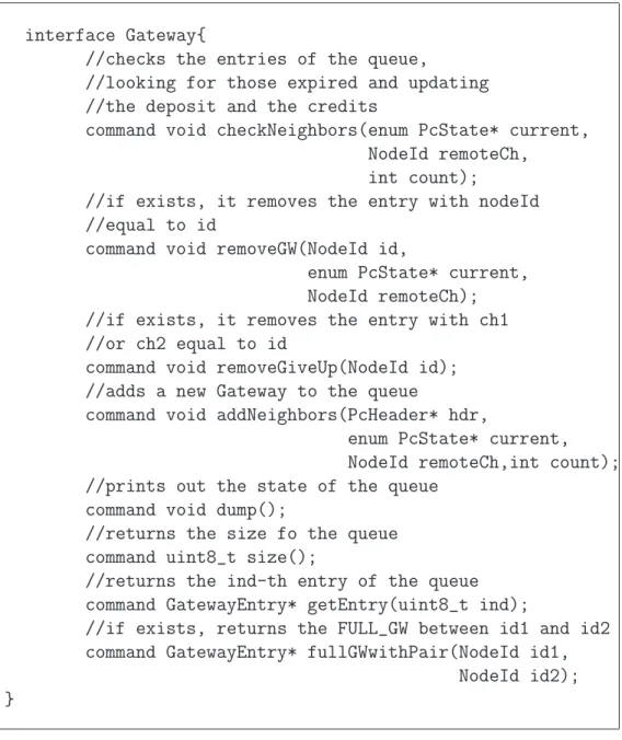
4.8 Gateway Interface . . . 40
4.9 Clusterhead Interface . . . 42
4.10 Transmission Packet Procedure (excerpt) . . . 43
4.11 Reception Packet Procedure (excerpt) . . . 44
6.1 Example of a Log File . . . 60
Ringrazio dunque tutti quelli che al TKN mi hanno consigliato e guidato, in particolare il Prof. Wolisz, Vlado, macedone avaro di sorrisi ma dall’inesau-ribile disponibilit´a, e il Prof. Avvenuti per avermi dato a Pisa l’opportunit´a e il sostegno necessario per partire.
Ben pi´u scivolosa e ripida sarebbe per´o stata la strada se al mio fianco non avessi avuto chi, anche nelle giornate pi´u buie, mi faceva sentire a casa. Gra-zie a Filip, Laia e a Luca per avermi distratto quando la tastiera diventava troppo grigia. Gracias a Alejandro y a sus sopas, a Bea (a.k.a. B.B.), a Gio-vanni, a Chiara, Alice & Milou, mes artistes pr´ef´er´es. Grazie a Rob, ultimo dei romantici, a Giulia e al suo passo sempre troppo in l´a. Grazie al compare Curi, ineguagliato maestro di Cucina e non solo.
Ma non ci sarebbe stata Berlino se non ci fosse stata prima Pisa. Grazie perci´o ai miei coinquilini Gabriele, Luca e Marco, per non avermi mai fatto mancare piatti e padelle con cui “rilassarmi” e soprattutto anni di ottima compagnia. Grazie a Veronica, ai suoi tormenti e ai suoi condizionamenti. Grazie a Elisqui, Francesca e Valeria per il loro insuperato crostino alle ca-rote e le innumerevoli serate. Grazie a Daniele, Elisa, Rox, Marta, Michela, Rocco (sempre sotto u’ palcu) e a Fedeh per i suoi “se beccamo” puntual-mente s´olati. Grazie a Simone, illuminante faro del Pacifico, e al Mao per la lontana visione di un ponte transoceanico. Grazie a Fede (a.k.a. Lido Peiani) che ad un sogno simile continua a credere, a Iggio, a Zon&Zibibbi (a.k.a. The Chess Brothers), a Saverioh (ovunque tu sia), a Tizi e a Giulia e a tutta la loro casa fiorentina. Grazie a Sara, insostituibile e instancabile tuttofare, al Ross, al Michi e al resto dei RainDay, al Guero, al Cetto, alla Dinetz, a Zedda, a Chiara, al Frizzo, a Letizia e a Laura, anche se mi sfianca ogni volta che si corre.
Grazie a tutti quelli che non ho qui lo spazio per ricordare ma che hanno contribuito a rendere questo periodo speciale.
Grazie alla maestra Riparbelli per le sue lezioni, ancora oggi le pi´u preziose. Grazie ai miei nonni, per le solide radici su cui sono cresciuto, a Floranna, ai miei zii e al mio cugino Andrea.
Un Grazie infinito a mia sorella, a mia madre e mio padre, per avermi strap-pato le pagine di Fisica quando era il momento e insegnato, tutti insieme, a trovare ovunque qualcosa per cui stupirsi.
Capitolo 1
Introduction
This chapter introduces to the main arguments of this thesis. First, we give an overview of Wireless Sensor Networks, commenting on their peculiar features and requirements. Later, the publish-subscribe interaction scheme is presented as a suitable communication model for this class of network. Last section points out the objectives and the motivations of this thesis.
1.1
Wireless Sensor Networks
In recent years research advances in highly integrated and low-power hard-ware permitted a new category of network to emerge. These are called wi-reless sensor networks (WSNs) and are composed from an high number of tiny devices, called motes, able to monitor or to control some physical pro-perties of their environment. They are provided with a small computation capabilities and with a wireless interface to perform basic communication. WSNs applications range from military scenarios[1], over environmental[3] and structural[2] monitoring to health monitoring[4].
The high number of devices should protect from link and node failures that frequently occur. A WSN has to exploit this redundancy to maintain its ef-fectiveness, so scalability and robustness become crucial issues. At the same time, motes power supply is generally provided by batteries which represent a limited energy resource. Then, it’s obvious that another important goal in application designing is power consumption optimization.
Also the communication scheme significantly changes in comparison with tra-ditional networks. In these, nodes are addressed individually through their
identities, therefore we refer that as an “ID-centric” model. In WSNs this ap-proach is neither feasible neither needed. It’s not feasible because of the high dynamism of the network: motes frequently die due to batteries exhaustion and new devices can be deployed as replacement. It’s not needed because a WSN application generally requests for environmental readings and it is inte-rested not in who actually does the monitoring but just in sensing and where these have been performed. For these reasons we speak of “data-centric” systems. In “ID-centric” communication model, as the client-server para-digm, a session for each interacting party has to be maintained. It’s clear that in networks composed from thousands of nodes such a scheme doesn’t scale at all. Instead, in “data-centric” networks, the set of interacting nodes is addressed defining the characteristics of requested data. This permits to abstract from single nodes giving a strong advantage when the sizes of the network grow. An example scenario where the “data-centric” model can be successfully employed is a temperature monitoring application for fires pre-vention in woods. Using a traditional approach, all the sensors spread in the wood have to be addressed separately. With a “data-centric” paradigm the application can just specify the threshold temperature over which the alarm should be released and then broadcast the request to the network.
The Publish-Subscribe interacting scheme represents an actual implementa-tion of “data-centric” communicaimplementa-tion model.
1.2
Publish-Subscribe
In literature various realization of “data-centric” communication model[5, 6] had been proposed. Among these, Publish-Subscribe (PS) communication paradigm emerges thanks to its loosely coupled form of interaction which make it so profitable to be used in WSNs.
The general structure of a PS system is showed in figure 1.1. Subscribers are nodes interested in some kind of information, they show their intention to receive data issuing a subscription message containing a description of what they are interested in, while, by issuing an unsubscription message, a subscriber declares he is no more interested in receiving notifications. At the other end of the scheme there are publishers, they “produce” and diffuse data (events) in form of notification messages. The interaction between publishers and subscribers is permitted by the Broker system which collects and correc-tly forwards, on the basis of subscriptions received from subscribers nodes,
1.2. PUBLISH-SUBSCRIBE Subscriber Subscriber Publisher Publisher Publisher Broker System Subscription Notification Subscription Notification Publish Publish Publish
Figura 1.1: General Architecture of a Publish-Subscribe System
the notifications sent by Publishers.
Recalling the example of fire alarm, the firemen station issues a subscription where it specifies to be interested in temperature events. Sensors spread on the area start to publish the readings of their surroundings in combination of location information. It’s up to the broker system to dispatch these surveys to the requiring stations on the basis of their subscriptions.
The properties making this paradigm particularly profitable regards identity, time and synchronization decoupling[10].
Identity Decoupling Interacting parties do not need to know each other. All the communications are based not on the identities of subjects but on the characteristics of data. In practice subscribers don’t have to know which are the publishers they should contact in order to obtain the requested information. Equally publishers have no idea about the identities and the number of subscribers they are providing.
Time Decoupling The parties do not need to be synchronized in their interaction. A subscriber can issue requests while there are no publi-shers active. Equally, publipubli-shers may start producing events without caring if there are subscribers interested in. Eventually, it’s a duty of the Broker system to cache messages and subsequently to deliver them.
Synchronization Decoupling Notification are published without blocking publishers and subscribers are asynchronously notified of a received event via a callback function.
These properties, in particular the decoupling on the identities, improve the scalability and the flexibility of the network by removing any coordination
and synchronization requirements. As the sender is unaware of its interac-ting parties, any limitation on the scalability coming from an identity-based addressing scheme is removed. At the same time that makes the communi-cation model highly versatile to nodes failures and new motes deployment. Various implementations have been proposed, section 2.1 explains which of these is more suitable to be used in a WSN and why. From those considera-tions it comes out that it’s a good idea to distribute the broker functionalities over all the WSN. In such a way, utilizing the computation capabilities of nodes, it’s possible to maintain the degree of scalability and to obtain consi-derable savings in radio transmissions.
Following this solution, the choice of the methods for the diffusion of sub-scriptions and for the collection of notifications becomes an essential design aspect.
1.3
Goals
The distributed approach to broker system implementation puts new design questions which have to be answered. As example, based on the composition of the network, it could be more attractive to distribute subscription or noti-fication. Reflecting on a common WSN, having a huge number of publishers (sensors) would suggest to diffuse subscriptions and to filter out notifications as closer as possible to events sources1.
A knowledge of the characteristics of the application scenario may lead to different choices in the system configuration. As example, the middleware can allow to separately select different protocols to collect events or to diffuse subscriptions. This flexibility, in addition to a knowledge of the application requirements characteristics, should help to obtain an effective and efficient solution for such processes. In example, one scenario may set specific con-straints which one protocol is not able to respect or, knowing the probability of motes failures, useful savings on the scarce resources available can be ob-tained by choosing a solution rather than another. So, how to understand which protocols is more suitable for our needs? Concentrating on the proto-cols for the distribution of subscription messages, this thesis tries to answer this question. It investigates two possible solutions for subscriptions diffusion and its objective is to supply some considerations, supported by simulation results, which would help an operator to select the best one for his scenario.
1.3. GOALS
This investigation has been carried out within the TinyOS[9] framework, which represents a standard implementation platform for WSN applications. It takes inspiration from a TinyOS implementation of a PS middleware, de-scribed in 2.2, which allows to independently select different protocols for subscription and notification diffusion processes.
The first configuration makes use of the Drain protocol for collecting no-tifications and the Drip protocol for the diffusion of subscriptions. Both of them are already implemented as TinyOS components. Instead in the second configuration, Drip is substituted by a simple broadcast protocol. But here a new component, based on the Passive Clustering (PC) protocol, organize the network in clusters. Then a first contribute of this thesis is the imple-mentation of Passive Clustering scheme as a TinyOS component.
The rest of the thesis is organized as follow: chapter 3 contains the description of these protocols while in chapter 4 the PC implementation is commented. As simulation tool, it came naturally to choose TOSSIM [7], the TinyOS si-mulator. Since it compiles directly from the TinyOS code, it doesn’t require to write a specific version for simulation purposes of protocol implementa-tion.
Once chosen the simulator, it has been defined the the plan and the metho-dologies of simulations, these are described in chapter 5.
Finally, the results from these simulations are presented and analyzed in chapter 6 .
Capitolo 2
The Publish-Subscribe in WSN
This chapter introduces in more detail the Publish-Subscribe scheme into a WSN context. First it is indicated which version of the model it’s more suitable for such networks. The second part gives a brief overview of the actual TinyOS implementation of a PS middleware, pointing out its main design features.2.1
Model definition
In the introduction the Publish-Subscribe scheme has been described as a sui-table communication model for WSN interactions. Several aspects remains to be defined.
It has already mentioned that, for the Broker system, a distributed imple-mentation is preferable. In fact, a centralized approach creates strong asy-mettries in traffic patterns since all the notifications and all the subscriptions are sent to an unique entity. Because of that, motes closer to the Broker will perform more radio transmissions than others and will consume faster their batteries. More, since the matching is executed by the Broker node, all the notifications have to be sent, even those which will not match any filter. It’s clear that this waste in transmissions is not allowed in a system where the energy consumption is a critical resource. Then it comes naturally to prefer a distributed approach where the filtering is pushed as close as possible to data sources and motes, so to perform locally the matching and to save unuseful transmissions.
a WSN, there is still something to clarify. What has been omitted it’s the description style of desired data. In literature these are traditionally resumed in three classes:
• Subject-Based description style
• Type-Based description style
• Content-Based description style
Among these, the one that better suits to a distributed PS model is the last. It cannot be explained why that one is preferable to the others without introducing its basic concepts.
Content-based The Content-Based style[11] is the most flexible among the data description styles. Here a subscriber describes the characteristics of interesting data through logical predicates. In detail, a subscription
s defines a filter F specifying a tuple composed from an attributes, an
operations and a values.
Attribute It defines the property a subscriber is interested to. The set of possible attributes is specified statically, according to the publishing capabilities of nodes. This choice strongly limits the expressiveness of the style but it permits to simplify the matching and forwarding operation and new attribute types can still be added at every time.
Operation Every attribute has a distinct set of operation can be ap-plied on. This set is firstly composed from the common equality and ordering operations but it can be arbitrarily enriched of mo-re complex operators. As only limitation, they have to mo-return a boolean result.
Value This element is used in the matching process together with the specified operation. It must belong to the valid domain defined by the couple attribute/operation.
On the other side, a notification n is constituted by the couple (attributen,valuen)
and it matches a given filter F, specified by (attributef,operationf,valuef),
if:
2.2. CONTENT-BASED PUBLISH-SUBSCRIBE: A TINYOS IMPLEMENTATION
The set of matching notifications is indicated by N(n,F(n)=T) and a filter F1 is said to cover a filter F2 if and only if N1 ⊇ N2.
It’s now evident the richness of this style. By forcing to describe desired data with this so fine grain level, it permits to filter out unwanted events and to save unuseful transmissions.
In addition to that, its grammar efficiently assists the aggreation of two
co-vering filters into a single one. In this way the matching is performed just
on the aggregated filter and possibly just one istance of notification is tran-smitted. Unlike a type-based description, the content-based style achieve these results without requiring any specific language support and maintai-ning a good level of scalability and flexibility. Concluding, a Content-Based Publish-Subscribe with a distributed architecture for event dispatching ap-pears as the best solution in a WSN context. The next section describes an actual implementation of such a system within the TinyOS framework.
2.2
Content-Based Publish-Subscribe: a
Ti-nyOS implementation
In this section it will be briefly presented the actual version of Publish-Subscribe middleware[12] we used for performing our protocols evaluation. While describing the key-points of this architecture, some design choices will be discussed and explained. As first, the implemented PS, for the reasons gi-ven in the previous section, belongs to the class of distributed content-based PS.
This implementation is realized within the TinyOS framework which impo-sed itself in last year as a standard de-facto for WSN applications. Section 4.1 is dedicated to TinyOS and its main features. By the moment, it would be sufficient to anticipate that, while traditional systems are composed from a stack of monolithic layers, a TinyOS application is built by small compo-nents wired through common interfaces according to the specific needs. This organization permits to optimize the usage of the scarce resources available on WSN hardware, excluding unuseful functions which otherwise would have been present using traditional layer scheme.
In such a framework, the three Publish-Subscribe actors are mapped almost one to one into these basic units. Figure 2.1 shows the architecture of the implemented middleware. There is a Broker component which is responsible:
• for subscriptions and notifications dispatching;
• for storing received subscriptions in sensor memory;
• for performing the filter matching.
One of the key feature of this implementation is the clear separation between PS middleware and the routing components used to diffuse notifications and subscriptions. An important design goal is to make PS component comple-tely independent from particular routing protocols. As in this thesis, this allows to test and to interchange different algorithms which would better suitable in a specific scenario. In practice, just a wrapper component for a particular routing protocol is added to the compiled application. This has to bridge the general Broker interface to the ones provided by different routing units.
Regarding the Broker component, it actually doesn’t perform filter matching but, through an AttributeContainer component, it just“orders” to execute the matching, which is realized by an attribute specific component. That is one of the most important design goal: making the Broker agnostic to attribute semantic. In such a way, if new sensors are added to the mote, giving the possibility of interrogating for a new physical property, the core of the middleware will remain untouched and just a new component for that attribute will have to be written.
Also Publisher and Subscriber are realized by single components. This orga-nization allows to exclude their functionalities from the compiled application if not needed (i.e. a sensor intended for just sensing light will not need to include the Subscriber unit).
Regarding exchanged messages, the content-based model provides that a sub-scription includes an attribute, an operation and a value while a notification is specified by a couple (attribute,value). The attribute name has to be globally unique, while operations and values are attribute-specific. This implementa-tion requires that all the possible attributes are described in a catalogue with their details (possible operation, range of admitted values). This catalogue is distributed in a form of an XML[13] file and at every moment just one version of this file can exist to preserve the uniqueness of afttribute IDs. In real application it would be useful to add also something more to better characterize the requested information. As example, a Subscriber could not be interested in receiving a survey every second, but it could consider suf-ficient a notification per minute. This extra-information doesn’t contribute
2.2. CONTENT-BASED PUBLISH-SUBSCRIBE: A TINYOS IMPLEMENTATION
to the matching process but represents a desired property of data collection process. Since in a WSN it is crucial to define as best as possible the cha-racteristics of desired data in order to limit any waste in transmissions and communications, therefore it makes sense to add these statements, called
commands, to subscription messages (see fig. 2.2). Regarding notification
symmetric observations can be made. As example, a publisher could want to inform he can’t sample the light at a rate faster than a certain value. This constraint can formally be seen as a filter on requests issued by subscribers and could prevent those from sending inapplicable commands (see fig. 2.3). Resuming in the exchanged messages could be distinguished two kind of information: data and metadata. Data, the couples attribute-value in no-tifications and the constraints in subscriptions, takes part in the matching process, while metadata, commands in subscriptions and constraints in no-tifications, contributes to characterize the data collection process.
In detail, subscriptions and notifications have a formally and semantically similar message format, both contain an header field and a payload. The header carries information exchanged by Broker components such subscrip-tionID or other flags. The payload is splitted in two parts, a first composed from an arbitrary number of couples (attribute, value) and a second com-posed from an arbitrary number of triple (attribute, operation, value). For subscriptions, a couple represents a command to be executed on the specified attribute while a triple contributes to define a filter for data matching. On the other side for notifications, a tuple represents the sampled data while a triple a constraint on a property of its data collection process.
Broker Subscriber Agent Application Publisher Agent Routing Component Attribute Container Attribute X Component Routing Wrapper
Figura 2.1: Component Scheme of the TinyOS PS Middleware. Yellow boxes represent middleware component, connecting lines represent interfaces and are represented external components. Just the main components are depicted
2.2. CONTENT-BASED PUBLISH-SUBSCRIBE: A TINYOS IMPLEMENTATION SubscriptionID Flags Length Value Operation Attribute Attribute Value Subscription
Header Subscription Command
Figura 2.2: Subscription Message Format
Value Value Operation Attribute Notification Header Notification Notification Metadata SubscriptionID Flags Length Attribute
Capitolo 3
Communication Protocols
In this chapter we present the protocols used in this study and their main im-plementative aspects. The first section introduces Drain, used for collecting notifications from motes to the base station. Second and third sections give a brief description of protocols employed to propagate subscriptions from the base station to motes. First we present the simple Broadcast protocol, then Drip protocol will be explained in details. On the last section Passive Clu-stering is presented in its main properties while its TinyOS implementation is described in the chapter 4.
3.1
Drain
Drain protocol is used to collect information from the network. Who is interested in collecting data, starts building collection routing trees. Every tree is identified by its root and an instance number, but at one time just one tree per root can exist.
3.1.1
Building a routing tree
The building of a tree starts from the root using beacon messages (their format is showed in fig. 3.1).
These are broadcasted in the network and among other information they contain the current cost of the route covdred at the moment. This cost is possibly estimated using information collected by lower layer protocols, as the LQI (Link Quality Indicator) provided in the message by CC2420 radio stack.
source 2 bytes 2 bytes parent cost 2 bytes ttl 1 byte beaconSeqno 1 byte beaconDelay 1 byte treeInstance 1 byte beaconOffset defaultRoute 2 bytes 1 byte
Figura 3.1: Beacon Message Format
A time to live field and a sequence number, relative to the particular instance of the tree, are also included to control the flooding process of beacons. On reception, the disseminated route is stored if:
• It’s a new tree (unknown destination or different tree instance);
• It’s an update of an existent tree coming from parent node (same instance tree but newer sequence number);
• It’s a lower-cost route coming not from any of my child nodes. Then, the beacon message is retransmitted just one time if:
• It’s a new tree (unknown destination or different tree instance);
• It’s an update (same tree instance but greater sequence number). It’s important to notice that routes stored in the routing table have no expi-ration, they can be only substituted but not deleted because considered stale. This fact has important consequences on the interaction between Drain and Passive Clustering organization as we will see more over.
3.1.2
Using the tree
Once the tree is up, on sending messages the routing table is asked for the right next hop to the desired destination. If a route is found, the stored information are used to fill up the packet header, otherwise the destination address is set to the broadcast one. An important feature, which can be also disabled if not requested, provides the using of acknowledgments to obtain a more reliable delivery service. In that case, messages are always enqueued and they wait in queue for the positive notification of reception. In case of losses or collisions, the retransmission is scheduled by a backoff timer whose value grows up exponentially with the number of failed transmissions. Of course the advantages coming from the use of such a mechanism are payed
3.2. BROADCAST C 10 10 B A 11 10 10 10 11 11 11 B A 11 11 11 11 C 11 11 11 11
Figura 3.2: Multiple Sources Problem in Broadcast Protocol
in terms of delays. These can be considerely greater, especially in networks with an high loss ratio due to the channel unreliability.
3.2
Broadcast
The simplest way to spread information among nodes is broadcasting: once messages are received, they are forwarded again in broadcast on the radio channel. Of course a mechanism is needed to prevent packets from being retransmitted endlessly. To avoid that, this protocol provides a short header shall be added to messages. This header just consists of a sequence number which should permits to infer whenever we are receiving a new information or an old one. On reception an easy check is performed between this number and an internal protocol counter. If the value of the counter is greater or equal to the one contained in the header, then the node has received mes-sages newer than this one which is discarded. Otherwise the counter value is updated to the sequence number just received and the packet, which is now considered the most recent message received, is forwarded both to up-per layers to complete the reception and to lower layers for retransmission. The previous mechanism introduces important restrictions in the protocol which have to be taken in consideration. Apparently no limit is set to the number of sources. But it’s easy to notice that concurrent transmissions or losses of packets cause several problems since a new flooding operation can be started only once the previous one has completed.
Figure 3.2 shows what can happen otherwise. In a first moment the net-work is in a stable state with all counter synchronized and node starts a flooding operation. Nodes one-hop away from B receive the message, cor-rectly update their counters and schedule themselves for retransmission. In
the meanwhile on its side node C starts broadcasting an its own message with sequence number 10. Node A will surely rejects this new message since marked by a sequence number it considers old. Also node C will discard the retransmission coming from A. In such situation, node C should wait for network being newly stable to begin its flooding operation. In presence of losses this last condition is no more sufficient, in fact the flooding can stop but without all nodes having received a copy of the message and updated their counters. Then, since we are working with a very unreliable channel, in order to obtain a correct behavior from the protocol, we are forced to permit just one source injecting such messages.
In the actual implementation of the Broadcast protocol in TinyOS two more aspects should be pointed out. First, in order to mitigate the effects of los-ses, we modified the original version and received messages are retransmitted up to MAX RTX times. In particular an internal timer fires, randomly wi-thin an interval RTX INTERVAL set as parameter in protocol configuration, triggering the broadcast of messages and giving second chances to nodes to receive messages.
The protocol provides also for a reserved sequence number, used for high priority packets. Whenever a header containing such a sequence number is received, the sequence counter is reset to 0, the message bypasses the coun-ter check and it is accepted as the newest one. As example we used this mechanism to permit an easy injection of unsubscription messages.
3.3
Drip
As Broadcast protocol, also Drip protocol[15] offers services to disseminate information among the nodes of a network but it tries to reduce possible collisions coming from the blind flooding of the former protocol. Drip is built on the Trickle algorithm[14] which has interesting properties in terms of scalability and flexibility. For scalability it is meant the ability to work well in different kinds of networks, without any a-priori knowledge on the number of nodes and on their density. The second feature deals with the adaptation of propagation speed, and consequently of the overhead, to the current needs of the network. The desired behavior is to have a rapid diffusion for new versions of data, even if this costs in terms of transmissions. But after this initial phase the network should approach a stable state, then protocol traffic should decrease in order to save transmissions and energy. Nevertheless a low
3.3. DRIP
rate traffic is maintained to assure all the nodes get the same version and are kept up to date.
3.3.1
Trickle algorithm
The Trickle algorithm is based on a “polite” gossiping scheme. Data to be diffused are classified in different increasing versions, identified by some meta-info added to transmitted packets. Every node partecipating to the flood schedules a broadcast operation randomly within a period. But if, be-fore this instant, it hears the same version for a certain number of time from other nodes, then the transmission is delayed. That asserts there is no need to transmit the same information more than X times, it would be just an unuseful repetition. This method permits to maintain a relative low broad-cast traffic even in networks with high density of motes. The second property previously described, the adaptation of transmission speed, is achieved dy-namically scaling the period of transmission.
In detail the protocol state is defined by these variables:
• a counter c;
• a period τ ;
• a threshold k ;
• a timer t with a random value within the range [0,τ ];
• the current version of data φx.
Whenever identical versions are heard, the counter c is incremented. When timer t fires, currently stored version of data φx is broadcasted only if c < k, otherwise the transmission is aborted. After the period τ , the counter c is reset to zero and a new random value for timer t is picked up.
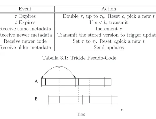
This is the standard running, but let’s see what happens if a newer or an older version is received. In both cases such a reception triggers an imme-diate event. If a node receives a summary with an old version φx-y of data, information needed to get the others node up to date are immediately broa-dcasted. In the other case, if it receives a summary resuming a newer version
φx+y, it broadcasts its own summary φx to stimulate the updates from the
Event Action
τ Expires Double τ , up to τh. Reset c, pick a new t
t Expires If c < k, transmit
Receive same metadata Increment c
Receive newer metadata Transmit the stored version to trigger updates Receive newer code Set τ to τl. Reset c,pick a new t
Receive older metadata Send updates Tabella 3.1: Trickle Pseudo-Code
Α Β
τ
Time
Figura 3.3: Short-Listen Problem in Drip Protocol
In the short introduction, we promised that this protocol provides a me-chanism to dynamically adjust the speed of data diffusion. It’s easy to see that with small values of τ , an high traffic but shorter propagation times are obtained, while with larger values the overhead is reduced together with diffusion speed.
The solution of the protocol is to dynamic scale τ between two boundaries
τl and τh. In particular whenever a newer version is received, τ is reset to τl,
while when τ expires without any update received, it is doubled up to τh.
Until this moment it has been silently supposed all the motes were synchroni-zed on the beginning of the interval but of course this condition doesn’t hold in a real scenario. There, the lack of synchronization and an unfortunate choice of timer value could lead to the so-called Short-Listen problem, whi-ch reduces the scalability of the protocol. Briefly, the Short-Listen problem happens when for timer t small values are picked up. As figure 3.3 shows, a node A selects a small t and transmits. Without synchronization on periods, other nodes can start to listen just after node A has transmitted. In this
si-3.3. DRIP channel ID 1 byte alignement 1 byte sequence number 2 byte payload
Figura 3.4: Drip Message Format
tuation everyone is ignoring each other and wasteful broadcasts are ordered. To remove this problem the value t is picked not from the interval [0,τ ] but from [τ
2,τ ] while the first half of the period is dedicated to listening. In this
case, in absence of losses, 2*k transmissions are sufficient to keep updated all the node at one hop of distance.
3.3.2
Drip as a Trickle implementation
As already said, the Drip protocol is built on the Trickle algorithm. It is implemented as a TinyOS component and it offers multiple channels for the reliable dissemination of information inside a network. Any user component interested in its data dissemination has to register an identifier which speci-fies the used channel.
Speaking of Drip, some details should be clarified. While describing Trickle algorithm it has been supposed that a summary of data would have been exchanged, in Drip what is actually spread instead are data itself.
As well, Drip needs a caching unit should be provided to satisfy periodic retransmission requests ordered by Trickle. Drip user components are re-sponsible for the storage of current version which they have to provide in response to rebroadcast requests.
In detail, metadata included in the Drip message (fig. 3.3.2) header and needed by the protocol consist of:
• a 1-byte channel id;
• a byte for the alignment;
• a 2-byte sequence number, used for version aging.
Clearly, the first field permits the identification of the channel used for dif-fusion of data while the sequence number is used to determine if the version
received is newer, older or identical to to the one currently stored. Here an half wraparound scheme is used but this doesn’t completely protect from very old version reception, in case of long-time partition of the network. Whe-never newer versions are received, the message payload is passed to upper layers for caching and other optional operations.
3.4
Passive Clustering
There is another approach to reduce the overhead coming from broadcast ope-rations: instead of using an explicit protocol to avoid unuseful transmissions, the network can be organized in subsets, called clusters, where just particular nodes are allowed to flood broadcast packets. Passive Clustering[16] belongs to this class of solutions and presents particular features which makes it sui-table to be used in a ad-hoc or WSN scenarios[17].
As in others clustering schemes, also in Passive Clustering network is parti-tioned in clusters where in each of them, nodes are elected to play particular roles, we have:
• Clusterhead nodes;
• Gateway nodes;
• Ordinary nodes.
Each cluster is identified with its clusterhead, which exerts local control and coordination, while different clusters communicate each other through ga-teway nodes. Flooding avoidance is performed allowing just clusterheads and gateways to propagate broadcast messages.
The assignment of these roles is the key aspect of every clustering scheme: an optimal mechanism would choose the minimal number of nodes to gua-rantee a complete connectivity of the network. Such a process introduces a significant overhead in terms of communication between nodes to get to the best solution. In some scenarios we would prefer building clusters more ra-pidly, saving on the number of messages exchanged, instead of waiting for the optimal organization. That is true especially in WSN and ad-hoc networks where energy consumption represents the critical aspect in system designing. Passive Clustering suits very well to these requirements since the main idea is: there is no need to keep up the cluster structure in absence of application traffic. Starting from this concept, any explicit control message is avoided
3.4. PASSIVE CLUSTERING
and all the information needed are piggybacked to application packets. This has the advantage of reducing any overhead coming from an explicit control protocol, saving a great number of transmissions. On the other side it forces the cluster organization to speed up, it’s not reasonable to wait that applica-tions exchange a great amount of traffic before having clusters formed. For this reason in Passive Clustering the selection process for clusterhead and gateways has to be approximated.
Clusterhead selection In order to achieve previous requirements the rule for clusterhead selection is the easiest, it says “Who first declares himself as
a clusterhead, then becomes as one”. In presence of ties, the node with the
lower node ID wins while the looser sends a give-up message in broadcast to inform its neighbors of its renouncing.
Gateway Heuristic selection Gateways are selected according to an Heuristic method. Here, a node which hears two or more clusterheads has a probability to become a gateway directly proportional to the number of clusterheads heard and inversely proportional to the number of gateways al-ready seen. Controlling these two coefficients of proportionality it’s possible to make trade-offs between the overhead given by more gateways and the redundancy and the connectivity of the network.
Passive Clustering provides also for the possibility of creating distributed gateways. A distributed gateway is composed from two gateways nodes logi-cally connected together to interface two of the clusters they are members of. The reason for that is avoiding the phenomenon of cluster rechaining which may happen when a “traditional” gateway fails.
The TinyOS implementation of PC had been one of the topic of this work and it is treated separately in chapter 4.
Capitolo 4
Passive-Clustering
Implementation
This chapter goes down in the details of component realization. The first section offers a brief and not exhaustive description of TinyOS framework and nesC language, involved in the implementation. In section 4.2 it’s given a general overview of how PC concepts and mechanism have been mapped into an actual TinyOS component. Later on,in sections 4.4 and 4.5 some excerpts of code are commented out, in the former referring to single components tasks and in the latter to main procedures.
4.1
TinyOS and nesC Language
This section gives a short overview on TinyOS[9] and nesC[8], respectively the operating system and the programming language involved in this imple-mentation.
TinyOS established itself as a standard operating system and as an imple-mentation platform for WSN applications. It is based on the abstractions of nesC programming language and as operating system it provides a scheduler and a set of library components.
A TinyOS application is a collection of components, coming from the ope-rating system library or on purpose written and coopeope-rating through well-known interfaces. TinyOS permits to include in the application just the components strictly needed and that makes it agile and suitable for WSNs. So far, components and interfaces have been just mentioned but let’s define
in detail what they mean in nesC semantic.
An interface is a collection of an arbitrary number of command and event handler declarations. Events and commands are conceptually similar to C functions, they are invoked respectively by signal and call statements. An interface can be provided or used by a component. In the first case, the providing component can signal the events specified in the declaration while it has to give an implementation of all the command handlers. On the other side, using an interface the component has to do the opposite: it has to im-plement all the event handlers while it can call its commands. An interface is said parameterized when it’s used or provided in multiple different instances, in other words what it is gives it’s an array of N identical interfaces. NesC syntax specifies that each component is divided in two sections. The first section is dedicated to interface declarations, specifying when they are
pro-vided or used, while the second part deals with component implementation.
At this point two kinds of component can be distinguished: configurations and modules. A module is the basic brick of nesC abstractions, it provi-des the implementation of its declared interfaces, while configurations create new components by wiring an arbitrary number of other components (both configurations and modules). With wiring it is meant the connection of a component which uses an interface with another component which provides the same interface.
The version 1.2 of nesC, used in this implementation, improves the expressive-ness of the language by the introduction of the concept of generic interfaces and generic components. Up to nesC version 1.1, an application could be composed only from single instance components. With these new features components can be easily parameterized by type and be instantiated in mul-tiple copies at compile time. For example, using generic components a Queue module can be parameterized by type of elements have to be stored in the queue and written just one time. Then at compile time multiple instances of this Queue can be created for different stored tuples with appropriate decla-rations.
As said before, TinyOS defines a concurrency model composed of two execu-tion contexts, one for synchronous code and one for asynchronous code. The synchronous context is dedicated to the execution of tasks, where tasks are deferred procedure calls. These are atomic with respect to other tasks (but not with respect to asynchronous code) and they wait for the execution in a queue scheduled with a FIFO policy. Asynchronous code is the one executed as response of hardware interrupts, such handlers do preemption on tasks
4.2. PROTOCOL FUNCTIONAL DESCRIPTION
1 bit 3 bit 1 bit 1 bit 3 bit 2 byte 2 byte 2 byte hello flag giveUp flag state PC
flag oldstate nodeId ch1 ch2 payload
Figura 4.1: Complete PC Message Format
and, if the specific platform allows it, can also interrupt the execution other lower-priority asynchronous code. When there is nothing to be scheduled, the microcontroller switches to sleep mode. This concurrency model is not safe from race conditions, but nesC provides also abstractions to access shared variables maintaining their atomicity.
As principle of good programming, to maintain a fast application responsi-veness in asynchronous handlers only the time-critical operation should be performed, whatever can be deferred, it has to be executed by tasks.
Concluding, TinyOS code can be compiled for many different hardware plat-forms and in particular, without any changes, an application version for the TOSSIM simulator, introduced in section 5.1, can be produced.
4.2
Protocol Functional Description
This section makes a general survey of Passive Clustering (PC) component, underlining and explaining its main design goals.
The principles of Passive Clustering organization scheme have been presen-ted in section 3.4, here they are restapresen-ted and mapped to their actual TinyOS implementation.
Clusters are built and maintained by exchanging of some information about the role of sending node. These PC headers are piggybacked to normal ap-plication traffic whenever sending node changes its state or after a certain time from the last sending of a PC header. Fig 4.1 shows the format of a message containing a PC header. The first flag is set if PC header informa-tion are piggybacked, its presence would trigger the examinainforma-tion of the rest of the header and the updating of component internal structure. The state and oldstate fields indicate the current state and the old state of sending node. The possible state are shown in table 4.2. Gateway and clusterhead selection processes need that each node is aware of the role played by other
Internal State External State
GW READY FULL GW
CH READY CLUSTER HEAD DIST GW INITIAL NODE ORDINARY NODE
Tabella 4.1: Passive Clustering Internal and External State
nodes in its radio range. These information are stored in four queues, one for each external state (FULL GW and DIST GW are joined in a single queue) and an expiration time is associated to every entry. That because in WSN scenarios the radio-channel is highly unreliable and motes can die, then this trick permits to refresh cluster states and remove stale entries. The details of queue management and updating are described in section 4.5.3. The oldstate field was not provided by the original IETF Draft[23] and had been added for optimizing the updating of component queues. If sending node had changed its state, its ID has to be removed from the queue where it was previously stored. The oldstate field permits to immediately choose that queue.
The giveUp flag indicates the message is informing the sending node is a clusterhead no more, in this case there is no payload. The hello flag is not currently implemented and the nodeId field is clearly the ID of the sending node. The two successive fields, ch1 and ch2 , are meaningful only if the received state is FULL GW or DIST GW, in these cases they represent re-spectively the primary and the secondary cluster IDs the announcing gateway is attached to.
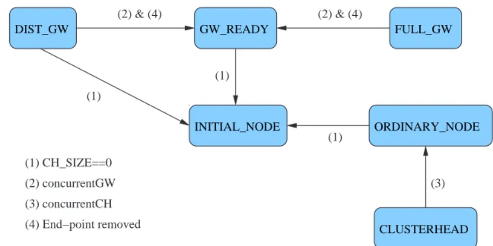
On reception the presence flag is checked: if packet contains a PC header, then as first operation the cluster structure seen by receiving node is updated. Expired entries,if there are, are removed from queues and the ID included in the PC header is put at the end of the proper queue.
Checking clusterhead and gateway queues may trigger an internal state up-date (fig.4.2). If clusterhead queue becomes empty and if the current node is not itself a clusterhead, it switches to INITIAL NODE state. Otherwise, if it’s a gateway and one of the clusterheads it was connecting have been removed, then its state changes to GW READY.
In second instance, the state of receiving node is recalculated on the basis of currently structure seen. A GW READY node may become an
ORDINA-4.2. PROTOCOL FUNCTIONAL DESCRIPTION FULL_GW GW_READY INITIAL_NODE DIST_GW ORDINARY_NODE CLUSTERHEAD (2) & (4) (1) (3) (1) (2) & (4) (1) (2) concurrentGW (1) CH_SIZE==0 (3) concurrentCH (4) End−point removed
Figura 4.2: State Transition Updating Queues
RY NODE if it sees enough gateway in its radio area and on the opposite, an ORDINARY NODE may switch to GW READY state if it sees a shortage of gateway nodes.
Separately it has to be considered the case of clusterheads and gateways con-flicts resolution. In that situation, the protocol specifies that the node with lower ID should prevail on the other. If a clusterhead hears about another clusterhead with lower ID, it looses the challenge and informs its neighbors immediately sending out a give-up message (with no application payload). If the challenge is between gateways, the IETF Draft states the one with higher ID should gives up but it doesn’t specify any explicit operation to be performed except the transition to GW READY.
After these tasks have been performed, the PC header is removed from the packet, the application payload is shifted to the head of packet payload and everything is passed up to higher layers. That is needed to keep transparent the insertion of PC component to the user components.
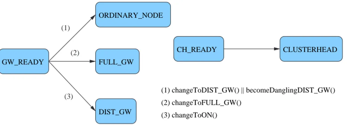
Operations executed on packet sending can be splitted in two main pha-ses: a first, resumed in fig. 4.3 , with node transition to an external valid state, and a second, concerning actual packet sending procedures.
In the first part, if the node is in one of internal states (GW READY or CH READY), it is determined to which output state should assume. In the case of CH READY there are no options, the node becomes a CLUSTE-RHEAD. Instead if it is in GW READY state it can become a FULL GW or
GW_READY FULL_GW ORDINARY_NODE DIST_GW (2) changeToFULL_GW() (1) changeToDIST_GW() || becomeDanglingDIST_GW() (3) changeToON() CH_READY CLUSTERHEAD (2) (3) (1)
Figura 4.3: State Transition on Packet Transmission
a DIST GW or a ORDINARY NODE. First, it tries to switch to FULL GW state. This attempt succeed if it finds two clusterheads for which it has not still heard a FULL GW connecting them. If this fails, the node may become a distributed gateway. A DIST GW connects a known clusterhead, named
primary (ch1 ), to a remote one (ch2 ) through another distributed gateway.
The aspiring DIST GW looks for a partner whose primary cluster is unkno-wn, once found it checks if other gateways (full or distributed) reach that cluster. If none has been found, than the node becomes a DIST GW and sets partner primary cluster as its remote one. If this also one fails, two options are left, the node may become an ordinary node or a dangling gateway. The former state it’s chosen if the node sees two or more clusterhead or if its clu-ster already has a distributed gateway. If no distributed gateways have been heard, then it becomes a dangling gateway setting its state to DIST GW and its remote cluster as unknown.
Once the node is in a valid external state, the type of sending determines whetever to apply flooding restrictions and header to the packet or not. If a unicast transmission has been ordered, no PC header is added and pac-ket is normally passed down to lower layer. In case of broadcast operations, the transmission is aborted if the node is a ORDINARY NODE or an INI-TIAL NODE. Otherwise if the node is a gateway or a clusterhead the broa-dcast is allowed and a PC header is added to packet if node changed its state or if more than a certain interval has passed from last PC header sent. Adding the header requires to right shift the application payload since the user component is not aware of PC layer.
4.3. IMPLEMENTATION OVERVIEW
4.3
Implementation Overview
The objective was to realize a new component, implementing Passive-Clustering functions, to be added to TinyOS library. Therefore it has to be perfectly integrable within TinyOS framework, without requiring any changes to exi-stent components.
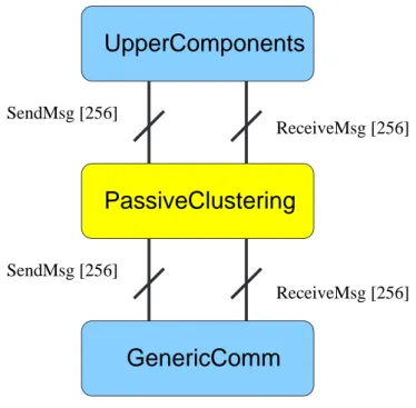
Before proceeding, it has to be introduced the Active Message (AM) model followed by TinyOS for network communication. The GenericComm is the component, included in the TinyOS library, which lays at the basis of this AM model, providing two parameterized interfaces, SendMsg and
ReceiveM-sg . Each packet on the network specifies in its header an handler ID which
permits to invoke the handler of the right interface on the receiving node. It can be seen as multiple ports (up to 256) were supplied for communications and this handler ID identifies to which port the packet is destined. In such view, the sending and receiving components have to share the ID of the in-terfaces they are wired to.
In this view, the Passive Clustering component should be placed just above the GenericComm , but it should look transparent both to this and to the upper components. To achieve that, it has to export exactly the same para-meterized interfaces of GenericComm as it is shown in figure 4.4.
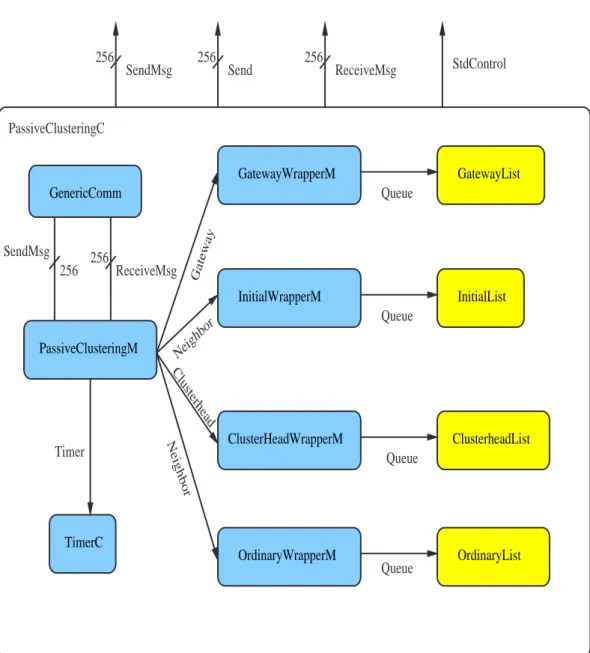
Let’s now open the box and describe the architecture of the Passive Cluste-ring component, represented in figure 4.5.
The core functions are performed by the module PassiveClusteringM whi-ch exports interfaces SendMsg , Send and ReceiveMsg and implements the gateway and clusterhead selection processes. To keep trace of the clusters state four queues are needed, one for each possible external state (DIST GW and FULL GW are grouped together). Queue components (in yellow in the figure 4.5) are instantiated at compile time from the generic component
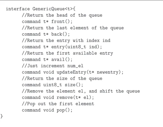
Ge-nericQueueM, which is parameterized on the type of stored elements. The GenericQueue interface offers the main functions of adding, deleting,
sear-ching elements in the queue, but different type may require more specific operations to be performed. From that it raises the need of wrapper classes, type-specific, which, using the basic services offered by GenericQueue inter-face, implement the appropriate type operations. In the following sections, first it is given a short description of the most meaningful components (sec-tion 4.4) and in a second instance the three main task are detailed explained in a inter-component view (section 4.5).
ReceiveMsg [256] ReceiveMsg [256] SendMsg [256] SendMsg [256]
UpperComponents
PassiveClustering
GenericComm
Figura 4.4: The AM Stack Modified
4.4
Component Detailed Description
In this section the most meaningful components are examined one by one. Their general functions will be described and some extracts of code will be commented.
4.4.1
GenericQueueM
This generic component had been written to parameterize a queue on the type of stored elements and it is usefully employed in the Passive Clustering architecture (see fig. 4.5). It exports the GenericQueue interface which offers the basic queue operations.
The queue is realized as a circular array of MAX EL NUMBER elements, the head is pointed by first index and the tail by last index. Insertion and ex-traction operations are managed with a FIFO policy and they are extremely simple. Extracting an intermediate element is the most complex operation since, once found the element to be removed, it requires to properly shift all the following entries.
4.4. COMPONENT DETAILED DESCRIPTION GenericComm PassiveClusteringM GatewayWrapperM InitialWrapperM GatewayList OrdinaryWrapperM InitialList OrdinaryList TimerC ClusterHeadWrapperM ClusterheadList PassiveClusteringC Queue Queue Queue Timer Queue 256 256 SendMsg ReceiveMsg Neighbor Clusterhead 256 256 256 StdControl
SendMsg Send ReceiveMsg
Gateway
Neighbor
interface GenericQueue<t>{
//Return the head of the queue command t* front();
//Return the last element of the queue command t* back();
//Return the entry with index ind command t* entry(uint8_t ind); //Return the first available entry command t* avail();
//Just increment num_el
command void updateEntry(t* newentry); //Return the size of the queue
command uint8_t size();
//Remove the element el, and shift the queue command void remove(t* el);
//Pop out the first element command void pop();
}
4.4. COMPONENT DETAILED DESCRIPTION
typedef struct NeighborEntry{ NodeId id;
long long int credit; }NeighborEntry;
typedef struct GatewayEntry{ NodeId id;
long long int credit; enum PcState state; NodeId ch1;
NodeId ch2; }GatewayEntry;
Tabella 4.3: GatewayEntry and NeighborEntry Type Definition
In PC implementation four instances of queues are created, three of
Neighbo-rEntry type and one of GatewayEntry for the Gateway queue. In comparison
with NeighborEntry, which includes the neighbor id and the left credit of the entry (see sect. 4.5.3), the GatewayEntry type permits to store the specific state (DIST GW or FULL GW) and also the cluster IDs a gateway is con-nected to. As already said the instances of this component are accessible through the appropriate wrapper components.
4.4.2
PassiveClusteringM
The core functions of protocols, such clusterheads and gateways selection processes, are implemented by PassiveClusteringM component. To be trans-parent to the communication stack, it provides the same interfaces of
Ge-nericComm while on the other side it uses those offered by that
compo-nent. It accesses to queues through the interfaces offered by wrapper classes. Operations performed on packets receiving and sending are described in sec-tions 4.5.2 and 4.5.1 respectively. Here methods related to gateway selection are commented. Regarding clusterhead selection, there is no much to say, since the transition to CH READY state, and then from that to CLUSTE-RHEAD, is constrained by nothing except the presence of other clusterheads. Different observations can be made for gateways, for them two are the main
module PassiveClusteringM{ provides{
interface StdControl;
interface ReceiveMsg[uint8_t id]; interface SendMsg[uint8_t id]; interface Send[uint8_t id]; }
uses{
interface StdControl as SubControl;
interface ReceiveMsg as GenReceiveMsg[uint8_t id]; interface SendMsg as GenSendMsg[uint8_t id];
interface Neighbor as Ordinary; interface Neighbor as Initial; interface Clusterhead;
interface Gateway;
interface Timer as Clock; }
}
4.4. COMPONENT DETAILED DESCRIPTION
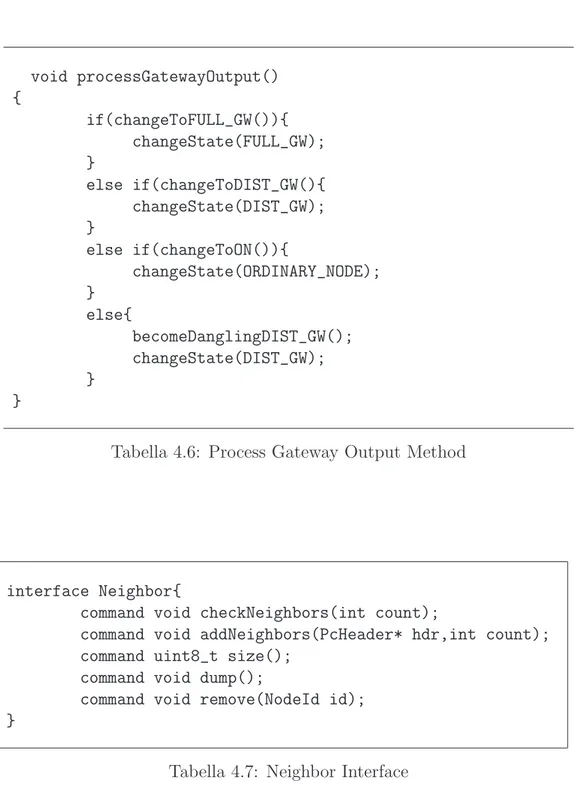
moments which compose the selection process. On packet reception the no-de sounds out the possibility of becoming a gateway, eventually switching to GW READY state: that is performed by processGatewayOutput method, shown in table 4.5. First, the changeToFULL GW and the
changeToDI-ST GW test if the node may become a gateway connecting two clusterhead
directly or via another distributed gateway. The second section of the method assures that in every moment cluster gets a minimum number of gateway. On packet sending, a candidate gateway checks if it can be definitely elec-ted as a gateway: that is done by processGatewayOutput(tab.4.6) method. Here again the changeToDIST GW and changeToFULL GW, together wi-th changeToON, check wi-the number and wi-the characteristics of gateways and clusterheads currently seen, implementing the heuristic selection process spe-cified by the protocol.
4.4.3
OrdinaryWrapperM and InitialWrapperM
These components deal with ordinary and initial nodes storing. They are treated together since they have almost identical implementations. In parti-cular they export the same Neighbor interface which adds to storing functions the method checkNeighbors to update counters and eventually remove stale entries.
4.4.4
GatewayWrapperM
The GatewayWrapperM exports the Gateway interface. It includes some specific methods for gateway search and extraction. Method fullGWwithPair returns, if present, the first FULL GW connecting two given clusters. A gateway can be removed fromthe queue in three cases, if its entry has expired (checkNeighbors), if the node previously registered as gateway changed its state (removeGW ) or in response of clusterhead give-up (removeGiveUp).
4.4.5
ClusterHeadWrapperM
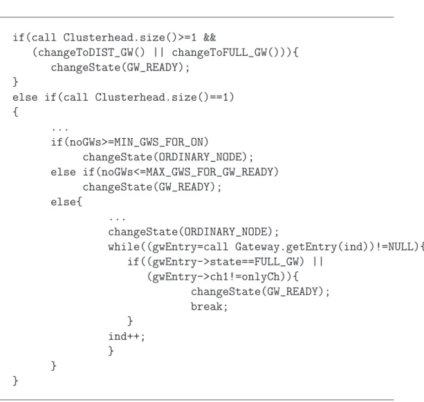
This component provides a wrapper for accessing to clusterhead queue. Among the standard services for queue management, it should be underlined the
re-moveAndApply method which has consequences on the state of the node. In
if(call Clusterhead.size()>=1 &&
(changeToDIST_GW() || changeToFULL_GW())){ changeState(GW_READY);
}
else if(call Clusterhead.size()==1) { ... if(noGWs>=MIN_GWS_FOR_ON) changeState(ORDINARY_NODE); else if(noGWs<=MAX_GWS_FOR_GW_READY) changeState(GW_READY); else{ ... changeState(ORDINARY_NODE); while((gwEntry=call Gateway.getEntry(ind))!=NULL){ if((gwEntry->state==FULL_GW) || (gwEntry->ch1!=onlyCh)){ changeState(GW_READY); break; } ind++; } } }
4.4. COMPONENT DETAILED DESCRIPTION void processGatewayOutput() { if(changeToFULL_GW()){ changeState(FULL_GW); } else if(changeToDIST_GW(){ changeState(DIST_GW); } else if(changeToON()){ changeState(ORDINARY_NODE); } else{ becomeDanglingDIST_GW(); changeState(DIST_GW); } }
Tabella 4.6: Process Gateway Output Method
interface Neighbor{
command void checkNeighbors(int count);
command void addNeighbors(PcHeader* hdr,int count); command uint8_t size();
command void dump();
command void remove(NodeId id); }
interface Gateway{
//checks the entries of the queue,
//looking for those expired and updating //the deposit and the credits
command void checkNeighbors(enum PcState* current, NodeId remoteCh,
int count);
//if exists, it removes the entry with nodeId //equal to id
command void removeGW(NodeId id,
enum PcState* current, NodeId remoteCh); //if exists, it removes the entry with ch1 //or ch2 equal to id
command void removeGiveUp(NodeId id); //adds a new Gateway to the queue
command void addNeighbors(PcHeader* hdr,
enum PcState* current, NodeId remoteCh,int count); //prints out the state of the queue
command void dump();
//returns the size fo the queue command uint8_t size();
//returns the ind-th entry of the queue command GatewayEntry* getEntry(uint8_t ind);
//if exists, returns the FULL_GW between id1 and id2 command GatewayEntry* fullGWwithPair(NodeId id1,
NodeId id2); }
4.5. DETAILED PROCEDURES DESCRIPTION
a clusterhead for which the node was a gateway, then this last switches to GW READY state.
4.5
Detailed Procedures Description
In this section three important procedures are described in detail. As first the reception and transmission procedures are taken up in a more organic view. Later on, it is explained the credits system which allows to keep queues up to date with a minimum overhead.
4.5.1
Sending a packet
The function responsible to manage the transmission process is
postProces-sFilter. As said in 4.4.2, it can be splitted in two parts: first it realizes the
transition from an internal state to a valid external one, later, on the basis of its state and packet address, it may deny the transmission.
Whenever the ordered transmission is allowed, the packet, provided by calling component, has to be manipulated. In particular, if the specified destination address is TOS BCAST ADDRESS, the TinyOS broadcast address, and one of the following condition stands:
• more than a certain amount of time passed from last PC header an-nounced;
• mote changed its state from last PC header announced.
then a PC header structure is put ahead of packet payload. But giving a look at the code, shown in tab. 4.10, the previous conditions seem missing. Here again a credit system, similar to the one of queue management, has been implemented. Variable credit is initialized after every transmitted header with a maximum value, NEW HEADER TIME LIMIT, and decremented up to 0 at every firing of the component timer, the same used for queue updates. In alternative credit is reset to 0 also if a transition between two different external state takes place. Therefore testing if its value is equal to 0, it’s equivalent to test both the previous conditions.
In both cases, if a PC header has been created or not, payload specified by the user component has to be right shifted, at least to take the flag field. The shifting is suitably realized through the efflength variable.
interface Clusterhead{
//removes the old entries and checks if //we were gateways for those entries, //in that case state switches to GW_READY
command enum PcState removeAndApply(enum PcState state, NodeId primaryCh, NodeId remoteCh, int cont);
//add a Clusterhead to the queue
command void addClusterhead(PcHeader* hdr,
enum PcState* state, NodeId primaryCh,
NodeId remoteCh,int cont); //return the queue size
command uint8_t size();
//return the front of the queue command NeighborEntry* front(); //return the back of the queue command NeighborEntry* back();
//return the ind-th entry of the queue
command NeighborEntry* getEntry(uint8_t ind); //checks if there is an entry with nodeId //equal to id
command NeighborEntry* IdEquals(NodeId id); //removes, if it exists, the entry with nodeId //equals to id
//no check if we are gateways or not for that entry command void removeCH(NodeId id);
//prints out the state of the queue command void dump();
}