Additive Manufacturing
of metal alloys
for aerospace application:
design, production,
repair and optimization
Studi di Salerno
FONDO SOCIALE EUROPEO
Programma Operativo Nazionale 2000/2006
“Ricerca Scientifica, Sviluppo Tecnologico, Alta Formazione” Regioni dell’Obiettivo 1 – Misura III.4
“Formazione superiore ed universitaria”
Department of Industrial Engineering
Ph.D. Course in Industrial Engineering
(XVI Cycle - New Series, XXX Cycle)
Additive Manufacturing
of metal alloys for aerospace application:
design, production, repair and optimization
Supervisor
Ph.D. student
Prof. Vincenzo Sergi Ing. Paolo Argenio
Prof. Fabrizia Caiazzo
Ph.D. Course Coordinator
Publication list
a) Journal articles
• “Laser beam welding of a Ti-6Al-4V support flange for buy-to-fly reduction”
F. Caiazzo, V. Alfieri, G. Corrado, P. Argenio, G. Barbieri, F. Acerra, V. Innaro,
Metals 7, 183 (2017) 10.3390/met7050183
• “Disk-laser welding of Ti-6Al-4V titanium alloy plates in T-joint configuration”
F. Caiazzo, F. Cardaropoli, V. Alfieri, V. Sergi, P. Argenio, G. Barbieri Procedia Engineering 183, pp. 219-226 (2017)
10.1016/j.proeng.2017.04.024
• “Reduction of surface roughness by means of laser processing over additive manufacturing metal parts”
V. Alfieri, P. Argenio, F. Caiazzo, V. Sergi Materials 10, 30 (2017)
10.3390/ma10010030
• “Redesign and manufacturing of a metal towing hook via laser
AM with powder bed”
D. Usera, V. Alfieri, F. Caiazzo, P. Argenio, G. Corrado, E. Ares Procedia Manufacturing 13, 825-832 (2017)
• “Laser Powder-Bed Fusion of Inconel 718 to manufacture turbine blades”
Fabrizia Caiazzo, Vittorio Alfieri, Gaetano Corrado, Paolo Argenio The International Journal of Advanced Manufacturing Technology (2017) 10.1007/s00170-017-0839-3
• “Study on the Factors Affecting the Mechanical Behavior of Electron Beam Melted Ti6Al4V”
Carmine Pirozzi, Stefania Franchitti, Rosario Borrelli, Fabrizia Caiazzo, Vittorio Alfieri, Paolo Argenio
Journal of Materials Engineering and Performance (2017) 10.1007/s11665-017-2894-1
• “Additive manufacturing by means of laser-aided Directed Metal
Deposition of 2024 aluminum powder: investigation and optimization”
V. Alfieri, P. Argenio, F. Caiazzo, V. Sergi
The International Journal of Advanced Manufacturing Technology 9(8), 1-12 (2017)
10.1177/1687814017714982
b) Conference Proceedings
“Mechanical properties of Inconel 718 in Additive Manufacturing via Selective Laser Melting – An investigation on possible anisotropy of tensile strength”
F. Caiazzo, V. Alfieri, G. Corrado, P. Argenio
3rd International Forum IEEE “Research and Technologies for Society and Industry, RTSI 2017”, Modena, ISBN 978-1-5386-3906-1
TABLE OF CONTENTS
Abstract
I
Preface on the Additive Manufacturing
III
1
Chapter_I Investment casting process of turbine blade:
redesign and manufacturing of mould by means of
Direct Selective Laser Melting of metals
1
1.1 Principles of Direct Selective Laser Melting
2
1.2 Investment casting process
4
1.2.1 The process
5
1.3 Experimental setup
8
1.3.1 AM powder features
9
1.4 Design and manufacturing of mould
14
1.4.1 First case study
15
1.4.2 AM production
16
1.4.3 Pattern preparation
21
1.4.4 Second case study
23
1.4.5 Pattern analysis
28
1.5 Cost and time analysis for mould AM construction
30
1.6 Conclusions
32
References chapter I
33
2
Chapter_II Additive Manufacturing via Selective Laser
Melting of turbine blades
35
2.1 Experimental setup: inconel 718 powder
36
2.2 Experimental procedure
38
2.2.1 Job preparation
39
2.3 Results and discussion
41
2.3.1 Tensile testing
41
2.3.2 Micro-hardness analysis
45
2.4 AM of the turbine blade
49
2.4.1 X-ray inspections
52
2.4.2 Am turbine blade dimensional analisys
53
2.5 Conclusions
56
3
Chapter_III Laser cladding as repair technology for
complex component in aerospace industry
61
3.1 Introduction to powder injection Laser Cladding
62
3.2 Powder laser cladding equipment
65
3.2.1 Laser source
65
3.2.2 Powder feeder
67
3.2.3 Manipulating sistem
70
3.2.4 Laser Cladding head
71
3.2.5 Beam nozzle
72
3.3 Experimental setup
73
3.3.1 Process tuning
74
3.3.2 Powder mass flow setting
75
3.3.3 Laser spot diameter setting
77
3.4 Experimental procedure
79
3.4.1 Composition
81
3.4.2 Single-trace deposition
82
3.5 Depositions for repairing of damages
87
3.6 Repair of a superalloy CM247LC guide nozzle vane
93
3.7 Conclusions
97
References chapter III
98
4
Chapter_IV Reduction of surface roughness by means
of laser processing over additive manufacturing metal
parts
101
4.1 Sourface roughness of additive manufacturing metal parts 101
4.2 Post processing treating for surface modification
103
4.2.1 Laser surface modification
103
4.2.2 Laser surface modification by means of scanning optics 104
4.3 Experimental setup
106
4.3.1 Materials and methods
106
4.4 Results and discussion
110
4.4.1 Starting roughness for as-built samples
110
4.4.2 Roughness and geometry of the fusion zone upon LSM 111
4.4.3 Microstructure and microhardness
115
4.5 Conclusions
118
References chapter IV
119
Abstract
Since its introduction, Additive Manufacturing (AM) has been used in aerospace applications. Rapid prototyping for saving capital and time during the product development period can be accomplished; moreover, significant influences on product design, direct part fabrication, assembly, and repair are benefited. Thanks to recent developments, AM has rapidly become a strategic technology generating revenues throughout the aerospace supply chain.
In this Ph.D. thesis, some applications of AM to the purpose of part fabrication and part repairing in aerospace are addressed; advantages and crucial features are discussed.
In chapter 1, the technology of Direct Selective Laser Melting of Metals, in the family of Additive Manufacturing processes, is considered to improve the process of investment casting of turbine blade. Design, manufacturing cost and time of a mould is investigated.
In chapter 2, Direct Selective Laser Melting is considered as an advanced industrial prototyping tool to manufacture Inconel 718 turbine blades at a pre-design stage before flow production. Expediting of the evaluation of any upgrades of both the part itself and tooling for assembly is aimed. To this purpose, possible anisotropy of manufacturing is preliminarily investigated via tensile testing at room and elevated temperature as a function of the sloping angle with the building plate; the normalized strength is given and compared with similar studies in the literature. Positioning and proper supporting in manufacturing are discussed; the parts are further investigated to assess their compliance with the intended nominal geometry.
In chapter 3, laser cladding is used to repair a nozzle guide vane, one of the main structural parts of gas turbines. With respect to traditional methods, this process allows to achieve reduced changes of the metal microstructure around the repaired zone, thanks to a more accurate deposition of a small volume of the filler material. Many parameters as laser spot diameter, powder feed rate, scanning velocity and laser power have been changed as main parameters in the experimental plan. An optimal overlapping rate has been set to generate a proper track size to address the actual damage.
In chapter 4, the issue of improving, by means of post processing, the surface quality resulting from AM is analysed. Laser surface modification as an alternative to conventional technologies has been investigated; also, laser beam wobbling has been considered in comparison with linear scanning aiming to reduce the affection of the parent metal and widen the scanning trace so to reduce the overall processing time. The results are widely discussed in terms of visual inspections, reduction of roughness, geometry of the
cross-section, microstructure and microhardness. Full experimental details are provided so that the results can be reproduced.
Preface on the Additive Manufacturing
In the industrial field the employment of innovative fabrication technologies is emerging to the purpose of cost reduction and flexibility. In particular, great interest is addressed to additive manufacturing (AM) techniques, which allow to obtain complex parts based on CAD models. AM enables the fabrication of parts with complex geometry that are impractical to be manufactured using conventional subtractive manufacturing methods. In addition, AM can be used to extend the life of in-service parts through innovative repairing.
Basically, all of the AM techniques employ the same basic principle: the final component is fabricated by means of layer by layer addition of the material.
Today, in addition to plastic material, several metallic materials including steel, aluminium, nickel-based superalloys, cobalt-base alloys and titanium alloys may be processed to full dense parts with properties complying with the requirements of industrial applications. Special interest has been devoted to AM in aerospace and biomedical industries thanks to the possibility of manufacturing high performance parts with reduced overall cost. Namely, in the aerospace this could lead to a reduction of required raw materials for in-service components, which is known as the “buy-to-fly” ratio. AM could also lead to innovative lightweight structures for several applications.
In the medical industry, AM is already leading to a revolution in customized medicine where dental implants, orthopedics, and hearing aids are manufactured to fit an individual’s unique physiology.
AM processes can be classified by the nature and the aggregate state of the raw materials as well as by the energy source. In AM of metals, powder raw materials or wire are fully melted by the energy input of a laser beam or an electron beam and transformed layer by layer into a solid part of nearly any geometry (classification: Powder-based or Wire-based AM).
In the following scheme a classification of the most important AM technologies is shown.
Fig. 1. AM technologies: Powder-based and Wire-based deposition AM
Powder-bed AM
In powder-bed AM systems, to prevent oxidation and possible fire due to fine particles, the process is performed in enclosed chamber which operated in vacuum or filled with an inert gas. The part and its supporting structures are manufactured in the same job, with the same material. In the center of the chamber, the metal powder is provided and layered by means of a leveling system. The chamber is then pre-heated to a pre-determined temperature depending on the process, around 100°C for laser-based processes and up to 700°C for electron beam. The laser or electron beam is then scanned over the surface of the metal powder along the pattern of the part, building up a single layer, usually between 20 and 200 μm thick. The building plate is then lowered by a single layer thickness, a leveling system provides fresh powder on top of the part, and the process is repeated until the final build is finished.
Electron Beam Melting (EBM)
In the EBM process an electron beam gun is employed as heat source. A focused beam of electrons is delivered to the powder bed, the kinetic energy is transformed into local heating to high temperatures and the powder particles melt, as a consequence.
As the process is conducted in vacuum to preserve the beam energy, gas shielding is not required. The advantage of the EBM process is that it has a faster build rate compared to laser-based powder bed systems. However, the surface roughness for EBM parts is higher and post machining is necessary depending on the applications.
Direct Metal Laser Melting process was developed by EOS GmbH of Munich and has been available commercially with the EOSINT M 250 laser melting machine since 1995.
During the DMLS process a laser beam scans the surface of the metal powder layer. The laser radiation is absorbed by the powder particles and heat is generated instantaneously in the powder layer, thus producing melting and thermal stresses.
The system operates in a protective atmosphere of inert gas such as nitrogen or argon. A wide range of materials are available to be processed, including but not limited to Al-Si-10Mg, CoCr superalloys, stainless steel, Ti-6Al-4V, Nickel-based alloys 625 and 718.
The resulting surface finish is higher with respect to the EBM process. However, the building rate is slower.
Heat treatment is required to decrease the thermal residual stresses or optimize the microstructure of the produced parts. In order to improve accuracy and surface finisching depending on the application, a post-processing (usually machining) is required.
Directed energy deposition AM
Directed Metal Deposition by means of laser beam is receiving increasing interest in the frame of AM to the purpose of maintenance, repair and overhaul of condemned products when severe conditions hindering the working order have been experienced. Minimal distortion, reduced heat-affected zones and better surface quality are benefited in comparison with conventional techniques.
Laser Powder Injection (Laser cladding)
In the technology of Laser cladding a powder is injected to provide the material to be deposited. A powder nozzle in combination with a laser beam is used to build o repair components consisting of single weld tracks. Side overlapping of the individual laser traces is required to process wider surfaces on 3D complex geometries.
The laser beam creates a melting pool on the surface part and the filler material is injected by a nozzle and melts as well. The solidification results in a metallurgical bonding to the base material.
Minimal distortion of the work-piece, reduced heat-affected zones and better surface quality are benefited in laser-aided DMD in comparison with conventional coating and repairing techniques such as arc welding or plasma spraying.
The laser powder injection approach is valuable because it can be used to add material to existing high-value parts for repairing and the powder material injected can be varied to fabricate compositionally graded parts.
The powder injection approach is not constrained to a confined volume as the powder bed systems are. Therefore, these systems can be used to process large parts.
Laser Metal Wire Deposition (LMWD)
This technique is capable of producing near-net shaped components by means of a laser beam as heat source and raw material as wire. During the process, gas shielding is required.
These techniques are similar to a conventional welding process and are well suited for manufacturing parts of high deposition rate and large volumes; however, the final product is limited by the inadequate geometrical accuracy and the surface roughness, so post-processing machining of the built part is required.
In addition to the these AM techniques, a range of other approaches are available, based on different types of energy inputs or materials. Among these, energy inputs can be provided by means of plasma arc welding equipment.
In this process, a device is used to generate plasma, either by direct current, alternating current or radio-frequency.
The electric arc is formed between the electrodes, then an input carrier or working gas is turned into plasma. Both wire and powder filler materials can be considered to deposit metals.
A plasma torch and positioning stage are manipulated by a robot or multi-axis controller and the path is pre-programmed. Powder is introduced both through the shielding gas and the orifice gas, and the plasma arc welding system provides the energy for melting.
1
Chapter_I
Investment casting process of turbine
blade: redesign and manufacturing of
mould by means of Direct Selective
Laser Melting of metals
In the industrial field, significant progress has been achieved in the development and application of Additive Manufacturing (AM), offering advantages of design freedom of structure and a wide choice of materials compared with conventional manufacturing [1].
In the aerospace the manufacturing of turbine blade is challenging since these parts are crucial for an aero-engine. Due to the significant influence of the geometrical shape and dimension of the turbine blade on the performance of the engine, strict dimensional tolerances are given for the machining process of the turbine blade. An accurate and effective machining technology is essential for the fabrication of a turbine blade. Therefore, shell-mould investment casting is widely used [2].
At present, moulds are manufactured by means of machining via CAD/CAM technologies.
Traditional investment casting suffers from high tooling costs for producing wax patterns. As such, investment casting is prohibitively expensive for low volume production like prototyping, customized or specialized component productions. The lead-time may range between several weeks to months depending on scheduling and capabilities of the factory. Therefore a toolmaker has to evaluate different mould designs before committing to manufacturing, since design errors or iterations are usually expensive and time-consuming to be amended or accommodated. Both the shape and the dimensions of tools for moulds are usually extremely accurate and, consequently, very expensive.
In this frame, in contrast to conventional, subtractive manufacturing methods, AM is increasingly investigated. Based on an incremental layer-by layer manufacturing, any part could be theoretically made [3]. Hence the development of AM provides new possibilities to integrate materials design, structure design, and functional design, to finally achieve a new strategy of design and fabrication. Direct Selective Laser Melting is one of the main methods for AM of metals: in this section, the importance of AM techniques
integrated with the investment casting process for various applications are highlighted.
1.1 Principles of Direct Selective Laser Melting
Direct Selective Laser Melting (DSLM) is a laser powder based technology to build objects layer by layer using metallic powder and laser. This process is structured in the following phases:
• The idea is translated into a CAD model;
• The CAD file is generally converted into STL, being it a faceted version of the model surface;
• The part is sliced, each slice having a typical thickness of 20÷40 µm; • Supporting structures may be required, therefore a proper position of
the workpiece with respect to the building plate and the scanning path for each layer must be set;
• The object is created by selectively fusing layers of powder with a scanning laser beam.
During this process, the laser radiation is absorbed by the metal powder and heat is generated instantaneously in the powder layer, thus producing melting. Stresses are produced as a consecquence of heating and melting; partial release is achieved when sintering the layers.
Figure 1.1: Powder bed AM process
To prevent oxidation and possible fire due to fine particles, the process is performed in closed inert chamber where inert gas atmosphere is continuously maintained so that the residual oxygen content is taken below 0.1%. Nitrogen or argon is fed into the chamber to prevent interactions of the metal powder with its environment and to protect the melt. The part and its possible supporting structures are manufactured in the same job, hence with the same material.
The powder is provided layer by layer by the recoater and a scanning head is used to deflect the laser beam.
Generally, at the end of the job, heat treatment is required to the purpose of reducing the thermal residual stresses or optimizing the microstructure of the produced parts. In order to achieve the high accuracy required for some parts or high quality surface finishing, a post-processing (usually machining) might be necessary.
The theoretical advantages of this technology are remarkable: • tools are not required, so the issue of tool wear is prevented;
• the process is capable of manufacturing parts of complex geometry based on 3D CAD;
• delivery time is reduced at pre-design stage; • good mechanical properties of the final part.
A number of applications of DSLM are currently considered: fabrication of inserts, injection and die casting moulds for series production and direct manufacturing of metal prototypes. This technique also offers great potential for mass customization, e.g., the fabrication of prostheses and implants for the biomedical industry.
1.2 Investment casting process
Investment casting (also known as ‘lost wax casting’ or ‘precision casting’) has been a widely used process for centuries. It is known for its ability to produce components of excellent surface finish, dimensional accuracy and complex shapes. It is especially useful for making castings of complex and near-net shape geometry, where machining may not be possible or too wasteful. It is also considered to be the most ancient process of making art castings. Technological advances have also made it to be the most modern and versatile one among all the metal casting processes.
In the field of aerospace technology, turbine blade is one of the critical components of aero-engine. Due to the significant influence of the geometrical shape and dimension of the turbine blade on the performance of engine, close dimensional tolerances are specified for the machining process of the turbine blade. The accurate and effective machining technology is essential for the machining of turbine blade. To do this, the shell-mould investment casting is widely used [2]. An appropriate die profile, which takes into account of the various shrinkages involved in casting process, is important for enhancing the quality of net-shaped products. Due to the shrinkages of the wax and solidifying alloy material, the geometrical size of the part produced by the investment casting process is smaller than that by the die cavity. In order to ensure the dimension accuracy, the position accuracy and the surface roughness, the wax pattern die profile design for turbine blade needs to consider the compensation of shrinkages brought by the solidification process. Due to the complex, time-consuming and expensive process of investment casting, traditional methods for designing die profile assume constant shrinkage rate.
Properties and considerations of manufacturing by investment casting: • Investment casting is a manufacturing process that allows the casting
of extremely complex parts, with good surface finish;
• Very thin sections can be produced by this process. Metal castings with sections as narrow as .015 in (.4 mm) have been manufactured using investment casting;
• Investment casting also allows for high dimensional accuracy. Tolerances as low as .003 in (.076 mm) have been claimed;
• Practically any metal can be investment cast. Parts manufactured by this process are generally small, but parts weighing up to 75 lbs (34 kg) have been found suitable for this technique;
• Parts of the investment process may be automated;
• Investment casting is a complicated process and is relatively expensive.
Consequently the investment casting process has increasingly been used to produce components for the aerospace industry and it has been particularly successful for the production of single crystal turbine blades.
1.2.1 The process
The first step in investment casting is to manufacture the wax pattern for the process. The pattern for this process may also be made from plastic; however it is often made of wax since it will melt out easily and wax can be reused.
Since the pattern is destroyed in the process, one will be needed for each casting to be made. When a lot of parts are produced, a mould for manufacturing patterns is needed.
The mould to create wax patterns may be cast or machined. The size of this master die must be carefully calculated. It must take into consideration shrinkage of wax, shrinkage of the ceramic material invested over the wax pattern and shrinkage of the metal casting. It may take some trial and error to get just the right size, therefore these moulds can be expensive.
Figure 1.2: Basic steps involved in ceramic shell investment casting
Often many wax patterns may be connected and poured together producing many castings in a single process. This is done by attaching the wax patterns to a wax bar, the bar serves as a central sprue. This arrangement is called a tree, denoting the similarity of casting patterns on the central runner beam to branches on a tree.
The metal casting pattern is then dipped in a refractory slurry whose composition includes extremely fine grained silica, water and binders. A ceramic layer is obtained over the surface of the pattern. The pattern is then repeatedly dipped into the slurry to increase the thickness of the ceramic coat. In some cases the pattern may be placed in a flask and the ceramic slurry poured over it.
Once the refractory coat over the pattern is thick enough, it is allowed to dry in air in order to harden.
The next step in this manufacturing process is the key to investment casting. The hardened ceramic mould is turned upside down and heated to a temperature of around 200F - 375F (90°C - 175 °C). This causes the wax to
Basic steps involved in ceramic shell investment casting:
(a) pattern production, (b) pattern assembly, (c) investment, (d) dewaxing, (e) casting, (f) knock-out, (g) cutoff,
(h) finishing and inspection (Kalpakjian and Schmid, 2008).
flow out of the mould, leaving the cavity for the metal casting. The ceramic mould is then heated to around 1000F-2000F (550°C -1100°C). This will further strengthen the mould, eliminate any leftover wax or contaminants and drive out water from the mould material. The metal casting is then poured while the mould is still hot. Pouring the casting while the mould is hot allows the liquid metal to flow easily through the mould cavity, filling detailed and thin sections. Pouring the metal casting in a hot mould also gives better dimensional accuracy, since the mould and casting will shrink together as they cool. After pouring of the molten metal into the mould, the casting is allowed to set as the solidification process takes place. The final step in this manufacturing process involves breaking the ceramic mould from the investment casting and cutting the parts from the tree.
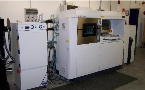
1.3 Experimental setup
The machine used for the experimental plan is an EOSINT M270 dual mode, including a laser unit, a control computer, a building chamber, a powder dispenser and a wiper blade. An ytterbium-fibre laser of 200 W, with a wavelength of 1.08 µm is used (implying high absorption of the laser radiation in the metal and good melting efficiency). The laser system uses a “dual focus” technology as a compromise to achieve resolution of details, reliable part density and high mechanical properties. Indeed, the spot size can be changed between 0.1÷0.5 mm. Namely:
• A shorter spot size is used to generate high definition “skin”, thus offering higher density, better surface quality and hardness;
• A larger spot size is used for “core” areas in order to reduce the building time and residual inner stresses, so to obtain uniform mechanical properties.
Laser is guided throught the optical fibre and focuses onto the powder bed. To prevent oxidation during melting and explosions because of thin powders, the process is performed in a chamber filled with nitrogen o argon gas which reduces the initial oxygen to 0.8%. In order to foster the junction between parts and buiding platform, which are usually made of the same or similar metal to be processed, and to reduce distortions the second one is heated and melting process starts when plate reaches 80 °C.
CAD data are downloaded, and then slicing is done on the workstation through EOS RP-Tools software. Multiple parts can be build in a single run on the steel base plate.
Table 1.1: Technical data EOS M270 (source: EOS)
Effective buiding volume (including building platform)
250 mm x 250 mm x 215 mm
Building speed (material-dependent) 2 – 20 mm3/s
Layer thickness (material-dependent) 20 – 100 m
Laser type Yb – fibre laser, 200 W
Precision optics F–theta – lens, high – speed scanner
Scan speed up to 7.0 m/s
Variable focus diameter 100 – 500 m
Current supply 32 A
Maximum power consumption 5.5 kW
Nitrogen generator standard
Compressed air supply 7000 hPa; 20 m3/h
Dimensions (B x D x H)
System 2000 mm x 1050 mm x 1940 mm
Recommended installation space approx.. 3.5 m x 3.6 m x 2.5 m
Weight approx.. 1130 kg
Higher precision is benefited with respect to additive manufacturing via electron beam; engineering tolerances are in the order of tenths of millimeters, that is with maximum deviation in the order of 0.2% when processing parts whose dimensions are comparable to the building chamber; deviation is lower for smaller parts.
1.3.1 AM powder features
Pre-alloyed, argon gas atomized virgin commercial EOS GP1 stainless steel powder, 20 µm mean grain size, corresponding to standard UNSS17400 chromium-copper precipitation hardening steel in terms of nominal chemical composition (Table 1.2) has been considered.
This kind of steel is characterized by having good corrosion resistance and mechanical properties, especially excellent ductility in laser processed state, and is widely used in a variety of engineering applications.
This material is ideal for many part-building applications (DirectPart) such as functional metal prototypes, small series products, individualised products or spare parts. Standard processing parameters use full melting of the entire geometry with 20 μm layer thickness, but it is also possible to use Skin & Core building style to increase the build speed. Using standard parameters the mechanical properties are fairly uniform in all directions.
Parts made from EOS StainlessSteel GP1 can be machined, spark-eroded, welded, micro shot-peened, polished and coated if required. Unexposed powder can be reused.
Typical applications are:
- engineering applications including functional prototypes, small series products, individualized products or spare parts;
- parts requiring high corrosion resistance, sterilisability, etc; - parts requiring particularly high toughness and ductility.
Table 1.2: Nominal composition (wt. %) of the powder; single values to be intended as
maximum
Cr Ni Cu Mn Si Mo Nb C Fe
15.0÷17.5 3÷5 3÷5 1 1 0.5 0.15÷0.45 0.07 balanced
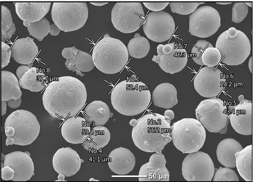
The powders have been produced by argon gas atomization. Compared with the process of atomization in water, regoular spherical shape is achieved. Electron microscopy has been performed to check the shape (Figure 1.4) and size distribution (Figure 1.5) of the virgin powder.
Figure 1.4: EOS GP1 electron microscopy powder particles morphology
Namely, the shape is found to be spherical and regoular; as regarding the size, dimensions are consistent with the expected range.
Figure 1.5: EOS GP1 powder particles size.
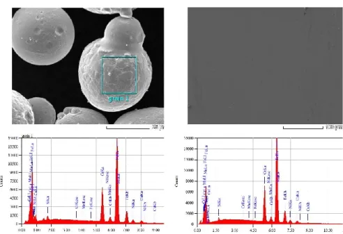
Furthermore, the virgin powder and some test samples have been investigated via aeral and punctual EDS inspections. The acquired spectra and the chemical compositions have been compared (Figure 1.6, Table 1.3). An average overall fitting coefficient of the quantitative analysis (i.e., the residual between the acquired and the synthetic spectra) of 0.89% and 0.78% resulted for the powder and the samples, respectively. At first, the EOS GP1 data sheet is matched in terms of nominal chemical composition; certain elements below 1% wt. have not been detected. Random transverse and longitudinal cross-sections of the samples have been considered; based on these, one may infer the referred nominal chemical composition has been taken during processing.
Figure 1.6: Examples of acquired EDS spectra for powder and samples, respectively
Table 1.3: EDS inspections, average chemical composition (wt.%) of powder and samples
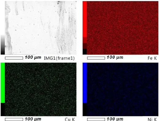
Uniform fusion has been experienced in the samples (Figure 1.7), as proven by EDS mapping of the main alloying elements.
Fe Cr Ni Cu Mn Si Mo Nb C Powder 72.70 16.75 4.46 4.87 0.33 0.90 - - -
Std. dev. 0.14 0.06 0.06 0.07 0.03 0.02 - - -
Samples 73.61 16.32 4.42 4.43 0.61 0.62 - - -
Std. dev. 0.13 0.06 0.05 0.07 0.03 0.02 - - -
1.4 Design and manufacturing of mould
The investment casting process has been increasingly used to produce components for the aerospace industry and it has been particularly successful for the production of single crystal turbine blades. When producing parts in any quantity, a mould from which to manufacture patterns is required. Today the mould to create wax patterns is usually made by means of machining.
Conventional manufacturing methods, such as turning and milling, may limit possible geometries of the final assembly. These limitations often result in structures that are inefficient, as many areas of a component have specific allowance that cannot be removed physically or via economically viable operations; indeed, conventional methods such as electrical discharge machining are empoyed.
The use of Additive Manufacturing process in the production of mould, improves current casting quality (optimize the cooling system), reduces manufacturing costs and explores new markets in order to remain competitive [4, 5]. In addition new features can be accomplished reducing the total number of parts of the assembly.
The aim of the present study is the development of a framework for redesigning existing components in order to exploit the benefits of AM [6,7]. This has been tested and validated through the redesign of an actual component, currently designed to be manufactured using conventional techniques. The objectives were to present a reduction of lead time and to preserve the overall mechanical and thermal features of the parts, so to bear with the shock loads.
1.4.1 First case study
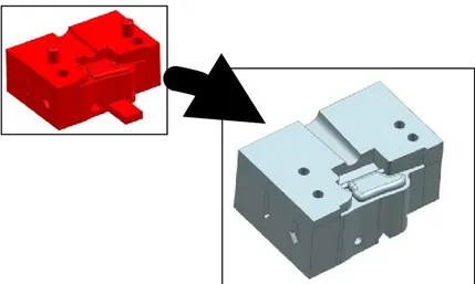
Two different steel moulds have been evaluated. The first model is composed of two parts and three tool insert. The latter are required to be machined to achieve complex geometry.
Figure 1.8: first model of mould
First of all a redesign of the mould has been implemented. The kind of redesign has been made taking into account the major feature of additive manufacturing that is the possibility to manufacture regardless the complexity of component geometry to be fabricated.
The redesign consist of the following stages:
• The part is build directly on the construction platform; • Tool inserts are integrated in the mould;
Figure 1.9:redesign of mould
1.4.2 AM production
An EOSINT M270 commercial laser melting system (EOS, Krailling, Germany) has been used to manufacture a job.
Processing power, speed, layer thickness, and hatching strategies are based on preliminary trials aimed to optimize the process and full dense structure (Table 1.4); a nitrogen inert atmosphere has been arranged.
Table 1.4: Main features and processing parameters in
selective laser melting of stainless steel powder
Gain medium Fibre, Yb:YAG
Operating laser power [W] 195 Linear processing speed [mm∙s-1] 1
Hatch spacing [mm] 0.10
Layer thickness [μm] 20
Focused spot diameter [μm] 90
Before performing the building job, proper corrective factors must be evaluated by means of a test-job to measure the effective processing diameter and take into account possible dimensional shrinkage.
Figure 1.10:test job for calibration machine
Moreover, a proper scanning strategy has been arranged. Namely, each layer is scanned in stripes and sectors: the section is subdivided into areas, each of them is scanned by the laser with side-to-side stripes.
Figure 1.11:scanning strategy
Based on the test-job and the scanning strategy, the dimensional accuracy of the components is expected to result in the order of tenths of a millimeter. The AM process has been performed, improper surface roughness resulted, therefore post-processing steps has been required.
1) stripes width 2) stripes overlapping 3) laser center trajectory
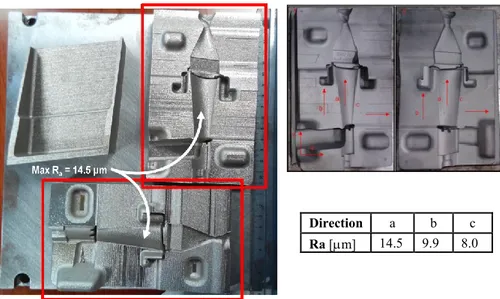
Figure 1.12: mould after production and measure of roughness
The first step is a post-process stress-relieving at 650 ºC for 1 hour. After stress-relieving, a dimensional analysis with the optical scanner ATOS 3D scanner GOM has been performed. The resulting deviation is in the order of tenths of millimeter, as a consequence of buckling of the building plate.
Figure 1.13:dimensional analysis with the optical scanner
The second step is shot-peening process of the surface to improve the surface quality. Therefore, in order to prepare the mould for wax injections, the surface roughness has been reduced. Shot-peening has been performed using the following parameters.
Direction a b c
Ra [m] 14.5 9.9 8.0
The treatment of shot peening reduced the roughness to an average value of 5.6 μm with a standard deviation of 1.75 μm.
The third step has been wire cutting via Electrical Discharge Machining (EDM) to cut the parts from the building plate.
Figure 1.15: final configuration mould
Subsequently a series of non-destructive test have been carried out, such as 3D measurements by means of a laser scanner and x-ray inspection.
First of all scanning by means of laser metrology has been performed to assess the geometry; the mismatch with respect to the intended original CAD file has been measured. Deviations in the order of hundredths of millimeter
Figure 1.14: job after sand blasting
Table 1.5: Shot peening parameters
Pressure 80 psi
Sand Washington mills
Composition Aluminum oxide Granulometry 120/220 Mesh
Time 4 min
have been found for the surface reproducing the airfoil of the turbine blade. The results are shown in Figure 1.16.
Based on X-ray inspections using a General Electric CRx flex CR scanner, all of the moulds have been found to be defect-free, as no indications have been shown in Figure 1.17.
Figure 1.16: dimensional analysis with the optical scanner
1.4.3 Pattern preparation
The pattern in investment casting has the exact geometry of the required final cast part but with dimensional allowances to compensate its own volumetric shrinkage as well as the solidification shrinkage of the cast metal in the ceramic mould. Wax, plastic or polystyrene are the common pattern materials among which wax is most widely used.
For the mould in question a pattern wax has been used. The wax have the following characteristics:
• It should have the lowest possible thermal expansion so that it can form a shape with highest dimensional accuracy;
• Its melting point should not be higher than the ambient temperature so that distortion of thick sections and surface cavitations can be prevented;
• It should be resistant to breakage, i.e. it is of sufficient strength and hard enough at room temperature so that it can be handled without damage;
• It should have a smooth and wettable surface so that a finished cast part with a smooth surface can be obtained;
• It should have a low viscosity when melted to fill the thinnest sections of the die;
• It should be released from the die easily after formation;
• It should have very low ash content so that it does not leave any ash inside the ceramic shell;
• It should be environmentally safe, i.e. does not lead to the formation of environmentally hazardous or carcinogenic materials upon combustion.
Costs, availability, easy of recycling, toxicity, etc., are the other important factors while selecting a pattern wax. The working efficiency of investment casting can be increased by improving one or more characteristics of the wax, by mixing additives, blending with different waxes and varying the process parameters.
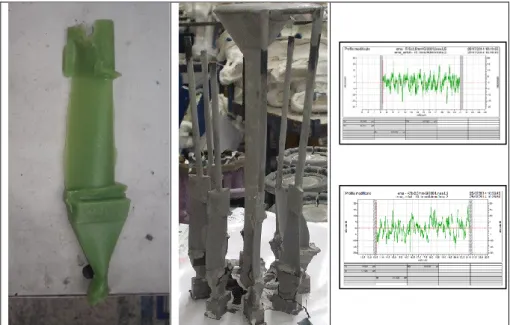
Finally a pattern of desired shape, has been produced by injecting molten wax into the AM-made mould. Then wax has been assembled to form a cluster to be casted to form the blades.
The result is shown in Figure 1.18. It is worth noting that the first injected pattern (first from left) is incomplete since the mould was improperly polished.
Figure 1.18:wax blades built to test the mould
After casting, the ceramic shell is removed thought mechanical methods to obtain the alloy blades. Roughness measures have been carried out on cast alloy blades in the longitudinal and transverse directions. The roughness is found to be higher with respect to the allowed standard.
Figure 1.19: turbine blade casting with AM mould (longitudinal and transverse profile,
1.4.4 Second case study
As second case study, a more complex mould consisting of 5 components has been considered. In this model the mould is decomposable to allow removal of the wax blade. The overall external dimensions are 250 mm × 60 mm × 65 mm.
Figure 1.20: second model of mould
Redesign for manufacturing is required to allow the fabrication via AM. Therefore, the following changes have been made to the original model:
• Reduction of the diameter of the plug holes from 6.5 mm to 4 mm; since an optimal surface roughness is not possible in AM, machining is required, hence the nominal dimensions are restored afterwards; • Replacement of the centering pins by holes for subsequent plug
insertion;
• Reduction from 2 mm to 0.1 mm of the depth of the component mark, so as not to apply internal supporting structures;
• Addition of 1 mm thickness allowance at the bottom of the part so to allow detaching of the component from the buildingn plate via wire EDM;
• Replacement of the centering block by a suitable geometric groove of proper shape and angle to prevent supporting during building. The application of the re-engineering criteria on the five components determines the variations shown in the Figure 1.22 obtained overlapping the original configurations and redesigned configurations.
Figure 1.22: overlapping the original configurations and redesigned
Mould elements are made in three separate job, using the same methodology and material as the previous mould. The components were arranged as shown in the Figure 1.23 to reduce deformations of buiding plate caused by material retraction.
Figure 1.23: moulds fabricated with AM on the construction plate
After fabrication, post processing must be performed, consisting in the following steps:
1. Heat treatment for stress relieving (650 ° C for one hour, in argon inert chamber)
2. Wire cutting by EDM to remove components from the building plate 3. Sandblasting
4. Mechanical machining to allow mechanical coupling of the moulds.
As mentioned above the main problem is the surface roughness of the component built. The first step was to perform roughness measurements on the aerofoil. The following table shows the values measured in orthogonal directions, i.e., horizontal (H) and vertical (V).
Figure 1.25:roughness measurements on the aerofoil
After AM fabrication, without additional machining, the average roughness is around 12 µm, which is still high for the application of the investment casting. Therefore, sandblasting has been conducted as for the first case study, thus improving the overall surface finish, with resulting reduced roughness in a measure of 50%, approximately.
Subsequently, in order to clean the mould from residuals of sandblasting, the moulds have been treated by ultrasonic washing. The cycle has been performed for a period of 10 minutes into water with proper cleaning agent. The surface of the mould after the treatments appeared under the following conditions with improved roughness.
Ra [μm] Rz [μm] 1 H 12.2 75.7 1 V 10.4 54.6 2 H 14.1 84.4 2 V 8.2 46.7 3 H 13.9 81.3 3 V 13.3 72.3 Ra [μm] Rz [μm] 1 H 11.6 74.3 1 V 10.6 54.2 2 H 11.8 76.0 2 V 13.2 66.5 3 H 13.5 86.8 3 V 9.3 49.7
Figure 1.26: mould after sandblasting and ultrasonic washing
Based on the test-job and the processing strategy, tolerances are expected again to match the tenths of a millimeter. A DEA Global Image Clima Coordinate Measuring Machine (CMM) has been employed to check these.
Figure 1.27: measurements detected by a CMM machine
Based on X-ray inspections, all of the mould have been found to be sound and defect-free, as no indications have been shown in Figure 1.28.
Max R
Figure 1.28: X-ray inspections
1.4.5 Pattern analysis
Castings with wax have been made to test the mould. After sand blasting the mould, an improvement in the injections has been noticed, both in terms of surface quality and in terms of extraction of the wax blades from the mould (i.e., the blades were intact).
Figure 1.29: wax blades casting with AM mould
Roughness analysis has been conducted on wax blades. Roughness values higher than the standard (1.6 µm) have been found.
Two measurements of roughness have been made on each sample as shown in the following table.
Table 1.6: roughness performed on wax blades
Sample
Ra(µm)
1 4.72 4.96 2 6.04 5.59 3 6.62 4.401.5 Cost and time analysis for mould AM construction
In the field of AM of metals, the purchase of the machine is the main cost. Indeed, the energy cost only contributes to minor level. Also simultaneous building of parts in the working chamber, rather than building a single part at a time, resulted in massive cost reduction. So it has become evident that in order to minimize the overall cost of the part, significant care must be taken to reduce the building time. It has been even proved that simultaneous building of an optimum number of parts is crucial to reduce time consumption.
In this case study, mould components have been produced in three jobs because the manufacturing of many parts in the same job would result in severe deformation during building. In the following table, the times and costs of each job are given.
Job 1 Job 2 Job 3
Time scheme [hours] Job 1 Job 2 Job 3
Redesign 3 3 1.5
Additive manufacture 75 78 30
Preparation job and
cleaning machine 3 3 2.5
Heat treatment 16 16 16
97 100 50
Cost scheme [€] Job 1 Job 2 Job 3
Material 300 300 120
Machine 2150 2250 850
Labour 405 405 250
Heat treatment 220 220 220
3075 3175 1440
It is worth noting that the longest time is the time for manufacturing; the higher cost is the cost of the machine. In detail, the cost of the manufacturing are given in Table 1.8.
Table 1.8: Detail of cost items
The partial cost of the whole mould is 7690,00 €. The cost of the mechanical machining to obtain the required tolerances must be considered as well.
Table 1.9: Times and costs for post-process mechanical machining Time scheme [hours] Job 1, 2, 3
Component removal with
wire EDM 63
Sandblasting 2
Hole finishing 7
Plate grinding 3
75 Cost scheme [€] Job 1, 2, 3 Component removal with
wire EDM 3200 Sandblasting 150 Hole finishing 360 Plate grinding 100 3810 Material Powder 70 €/kg Construction plate 5 €/job
Machine Energy 0.8 €/hour Inert gas 1.2 €/ hour Filter Depreciation
Labour Redesign Job design
Preparation and cleaning machine Heat treatment Energy Inert gas 0.8 €/ hour
Wire EDM to remove the parts from the buiding parts results in a significant effect of the overall price of the finishing.
As a consequence of this the total cost of the mould made by additive manufacturing is 11.500 €.
1.6 Conclusions
Fabrication of moulds by means of AM tecnique is possible, but the related costs are still high [5, 8]. However, it should be noted that the costs are evaluated in the assumption of prototyping activity, in fact similar moulds made with traditional techniques would present a comparable or even lower cost. With the development of these technologies and with the reduction in the cost of machinery and raw materials, great benefits in terms of time and cost of production would result.
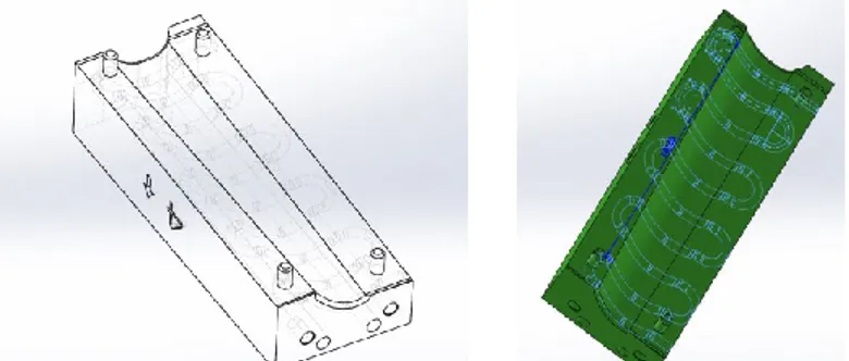
In addition, conformal cooling channels could be considered [9, 10], as shown in the Figure 1.30, to increase mould productivity with the control of mould temperature and part dimensions.
Figure 1.30: design of cooling channels conformal for thermal control of
References chapter I
1) Dirk Herzog, Vanessa Seyda, Eric Wycisk, Claus Emmelmann, « Additive manufacturing of metals, 2016 Acta Materialia Inc. Published by Elsevier Ltd.».
2) S. Jones, C. Yuan, «Advances in shell moulding for investment casting, Journal of Materials Processing Technology 135 (2003) 258– 265».
3) Sunpreet Singha, Seeram Ramakrishnab, Rupinder Singhc, « Material issues in additive manufacturing: A review, Journal of Manufacturing Processes,2016».
4) Konstantinos Salonitis, Saeed Al Zarban, « Redesign Optimization for Manufacturing Using Additive Layer Techniques, Procedia CIRP 36 ( 2015 ) 193 – 198»
5) Heidi Piili, Ari Happonenb, Tapio Väistöc, Vijaikrishnan Venkataramanana, Jouni Partanend, Antti Salminena, « Cost Estimation of Laser Additive Manufacturing of Stainless Steel, Physics Procedia 78 ( 2015) 388 – 396».
6) Mary Kathryn Thompson, Giovanni Moroni, Tom Vaneker, Georges Fadel,R. Ian Campbell, Ian Gibson, Alain Bernard, Joachim Schulz, Patricia Graf, Bhrigu Ahuja, Filomeno Martina, Vijaikrishnan Venkataramanana, Jouni Partanend, Antti Salminena, « Design for Additive Manufacturing: Trends, opportunities, considerations, and constraints, CIRP Annals - Manufacturing Technology 65 (2016) 737–760».
7) Sebastian Hällgrena, Lars Pejrydb, Jens Ekengrenb, « (Re)Design for Additive Manufacturing, Procedia CIRP 50 ( 2016 ) 246 – 251» 8) Wei Gaoa, Yunbo Zhanga, Devarajan Ramanujana, Karthik Ramania,
Yong Chenc,Christopher B. Williams, Charlie C.L. Wange, Yung C. Shin, Song Zhanga, Pablo D. Zavattieri, « The status, challenges, and future of additive manufacturing in engineering, Computer-Aided Design 69 (2015) 65–89»
9) Vegard Brøtana, Olav Åsebø Bergb, Knut Sørbya, « Additive manufacturing for enhanced performance of moulds, Procedia CIRP 54 ( 2016 ) 186 – 190»
10) Suchana A. Jahan and Hazim El-Mounayri , « Optimal Conformal Cooling Channels in 3D Printed Dies for Plastic Injection Moulding, Procedia Manufacturing Volume 5, 2016, Pages 888–900»
2
Chapter_II
Additive Manufacturing via Selective
Laser Melting of turbine blades
In the frame of Additive Manufacturing of metals, the aerospace industry has become increasingly interested in the use of Additive Manufacturing (AM) methods for the production of Ni-based high-temperature components. Selective Laser Melting is investigated in this chapter as an advanced industrial prototyping tool to manufacture Inconel 718 turbine blade at a pre-design stage before flow production.
As mentioned in the previous sections, new possibilities in lightweight design and direct fabrication of functional end-use parts are offered by Additive Manufacturing where the base material is provided layer-by-layer, unlike conventional turning and milling relying on removal from the bulk. Namely, Selective Laser Sintering (SLS) and Melting (SLM) are solid freeform fabrication techniques based on laser irradiation of metal powder. Assemblies are turned into single parts, hence streamlining of manufacturing and potential elimination of tooling are benefited. Moreover, customization is allowed and the mechanical strength of the bulk is achieved upon proper set-up, although the resulting surface quality may limit the application if compared with conventional metal manufacturing. Post processing treating is required indeed to the purpose of surface modification.
Among a wide range of possible applications of AM, interest is currently devoted to processing superalloys for aerospace and automotive where outstanding combination of superior mechanical properties and wear resistance are required in demanding environments.
Typically, the Inconel 718 superalloy has been developed and applied in wrought, cast, and powder metallurgy forms, and the parts manufactured using these methods have demonstrated superior mechanical properties and performances [1] [2]. However, it is difficult to control the performance of this material when casting or forging. Furthermore, rapid development of modern industry and advanced engine designs, which require complex structures, high dimension precision, and further elevated mechanical properties, puts more pressure on Ni-based super alloys and their production. Therefore, an application of novel processing methods is necessary for the net shape production of Inconel 718 parts with complex configurations and high performance requirements.
2.1 Experimental setup: inconel 718 powder
Inconel 718 (IN718), a solid-solution or precipitation strengthened Ni-based austenite superalloy [3], has been used for produce prototype turbine blade. This superalloy receiving increasing interest, as being widely used to produce exhaust pipes, parts for rocket motors, gas turbines and nuclear reactors.
Two main reasons are driving both scientific and industrial investigation about IN718 AM - made parts. At first, challenges are faced when addressing fabrication of IN718 parts at room temperature with conventional machining due to high shear strength and low material removal rate [4]; in addition, complex parts with specific internal geometries and tight dimensional accuracy are usually required in aerospace and nuclear industries, hence conventional machining would be unfeasible [5]. Since IN718 is well known for good weldability, thanks to slow precipitation strengthening kinetics resulting in reduced cracking occurrence, SLM is enabled [6].
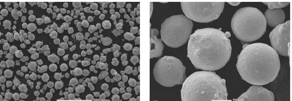
Pre-alloyed, 20 μm mean grain size, virgin EOS IN718 powder resulting from argon gas-atomization has been considered.
The powder has been preliminarily inspected in terms of size and geometry, since specific requirements of shape must be matched to the purpose of proper manufacturing. Spherical and near-spherical grains have been found (Figure 2.1), thus efficient flowing and layer packaging are expected to result in uniform melting [7].
Figure 2.1: Pre-alloyed, argon gas-atomized, virgin IN718 powder; electron microscopy
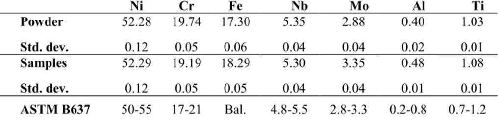
Furthermore, the virgin powder and the samples have been investigated via aeral and punctual EDS inspections using a JEOL Neoscope.
EDS inspections have been conducted both on virgin powder and random cross-sections of the samples, to assess possible variation in the nominal composition upon AM; 15 kV accelerating voltage, 1 nA probe current and 3 min probing live time have been set.
The acquired spectra and the chemical compositions have been compared (Figure 2.2, Table 2.1). An average overall fitting coefficient of the quantitative analysis (i.e., the residual between the acquired and the synthetic
spectra) of 1.9% and 2.9% resulted for the powder and the samples, respectively.
At first, the ASTM B637 standard is matched in terms of nominal chemical composition; certain elements below 1% wt. have not been detected. Random transverse and longitudinal cross-sections of the samples have been considered; based on these, one may infer the referred nominal chemical composition has been taken during processing.
Figure 2.2: – Examples of acquired EDS spectra for powder and samples
Table 2.1: EDS inspections, average chemical composition (wt.%) of powder and samples
Ni Cr Fe Nb Mo Al Ti Powder 52.28 19.74 17.30 5.35 2.88 0.40 1.03 Std. dev. 0.12 0.05 0.06 0.04 0.04 0.02 0.01 Samples 52.29 19.19 18.29 5.30 3.35 0.48 1.08 Std. dev. 0.12 0.05 0.05 0.04 0.04 0.01 0.01 ASTM B637 50-55 17-21 Bal. 4.8-5.5 2.8-3.3 0.2-0.8 0.7-1.2
2.2 Experimental procedure
As for any other metal alloy, the resulting mechanical properties upon AM are expected to depend on the final density, as a function of heat and mass transfer in turn [8], based on the main processing parameters such as the size of the laser beam, the laser power, the scanning speed, the layer thickness and the hatch spacing [9] [10]. Therefore, extensive research has been conducted to draw a correlation between densification and microstructure of IN178 AM-made parts; it has been shown that optimum processing strategies result in 0.3% residual porosity, with elongated grains along the building direction [5]. Wear and high-temperature oxidation tests have been also implemented [11] [12], since poor resistance would lead to severe degradation of service life in the operating environment.
Anisotropy in the mechanical behavior is expected upon layering, depending on the direction of building, due to columnar grain growth as a consequence of directional thermal conduction. As regarding SLM, anisotropy has been discussed in the literature for stainless steel [13] [14], titanium [15] and Ni-based alloys [16]; anisotropy has also been reported when AM is conducted by means of electron beam [17]. This issue is expected to be crucial for Ni-based super alloys which are highly anisotropic and are conveniently processed to the purpose of producing functionally graded components [18], indeed.
An approach to measure the degree of AM-induced anisotropy as a function of the direction of building has been proposed in the literature [14]: the normalized yield or ultimate tensile strengths are evaluated with respect to their counterpart as resulting from an in-plane (i.e., flat-built) specimen. Depending on the base metal [13] [14] [16], normalized strength in SLM is found to range from 0.8 to 1.1. The position of building in the working area has even been suggested as possible additional reason of anisotropy [14], although this effect is thought to be negligible when focusing and deflecting are driven by means of an F-theta lenses providing uniform irradiance and approaching speed over the working surface [19].
It is worth noting that depending on the manufacturer and the powder size, arithmetic as-built roughness in SLM usually ranges from 8 to 20 μm [20]: since rough and rippled surfaces are reported to have larger stress concentrations, the rate of crack growth when testing as-built samples is affected [17]. In addition, residual stresses resulting from thermal cycles during laser AM, may exceed the yield strength, thus involving delamination during processing, as well as affecting corrosion resistance, fracture toughness, crack growth behavior and fatigue performance of the part. With respect to this issue, IN718 parts have been found to be very susceptible to warping and buckling because of their higher residual stress to yield strength ratio [21]. Given this, neutron diffraction has been presented as a valid method to validate thermo-mechanical models so to predict the residual stresses on
Ni-based AM-made parts [22]. Heat treatment is usually suggested to the concurrent purposes of stress relieving and precipitation of parent strengthening phase [6].
To provide further understanding of the mechanical properties of IN718 AM-made parts, possible anisotropy is investigated in this study as a function of the direction of growth. Flat-, 45°- and upright-built samples have been produced. The tensile response at room and elevated temperature is discussed. Eventually, a batch of turbine blade, which are currently made via casting, has been manufactured and inspected by means of X-rays and 3D laser scanning metrology.
Three possible direction of growing are considered; corresponding supporting structures are designed, accordingly. Although AM is not deemed to be a current viable option to casting, the process is intended to offer a valuable technical test model in the frame of advanced industrial prototyping to evaluate any possible upgrade at a pre-design stage before flow production; furthermore, a preliminary evaluation of clamping and tooling for assembly is aimed. Therefore, proper mechanical features must be achieved and the same base metal must be used.
2.2.1 Job preparation
An EOSINT M270 commercial laser melting system with Yb:YAG fibre-laser source has been used to manufacture a convenient number of cylinders (12 mm diameter, 90 mm height); an F-theta lens is used to focus and deflect the laser beam over the working area. Flat-, 45°- and upright-built samples have been produced (Figure 2.3) in 99.4% pure argon inert atmosphere; supporting structures have been required on downward facing surfaces, depending on the sloping angle with the building direction, hence for flat- and 45°-built samples.
Operating laser power, speed and hatching strategies are based on preliminary trials aimed to optimize SLM and full dense structure (Table 2.2).
A number of quality jobs have been performed to assess and fine-tune the beam offset and the scaling factor to address possible dimensional shrinkage. Namely, a checkerboard scanning pattern with 67° rotation of the scanning direction between consecutive 20 μm thick layers has been set. To the concurrent purpose of stress relieving and ductility improvement [3], heat treatment as per AMS 5664 standard (i.e., solution annealing at 1065 °C for 1 hour, ageing at 760 °C for 10 hours, cooling to 650 °C and holding for 8 hours in argon inert atmosphere) has been eventually conducted before removal of the parts from the building plate, as suggested by the powder manufacturer [23].
Table 2.2: Main features and processing parameters in SLM of IN718 powder Gain medium Fibre, Ytterbium-doped YAG (Yb:YAG)
Operating laser power 195 W
Linear processing speed 1.2 m∙s-1
Hatch spacing 90 μm
Layer thickness 20 μm
2.3 Results and discussion
Uniform fusion is experienced. Overlapping lenticular-shaped melting pools result as a consequence of building and layer development [24] when investigating the samples (Figure 2.4); it is worth noting that although a scanning beam of theoretical 90 μm diameter is used, a wider scanning trace of approximately 120 μm width is found due to thermal conduction. Moreover, the typical 67° scanning angle between exposures over consecutive layers is measured if a cross-section is made orthogonal to the direction of growing (Figure 2.5).
Figure 2.4: Layer development, longitudinal cross-section in the upright-built sample
Figure 2.5: Exposures over consecutive layers; transverse cross-section in the
upright-built sample
2.3.1 Tensile testing
Subsize specimens with round cross-section, as allowed by ASTM standards [25] [26], have been produced via turning of the cylinders, in agreement with similar research in the literature [16]. The same standards have been referred for testing at room and elevated temperature; namely, tensile testing at 650 °C has been conducted, being this the maximum operating temperature for IN718 AM-made parts under load, as per material data sheet [23]. Investigation on near-net-shape AM-made tensile specimens, with no