DIPARTIMENTO
DI
INGEGNERIA
INDUSTRIALE
Dottorato di Ricerca in Ingegneria Meccanica
XIV Ciclo N.S. (2012-2015)
“Additive Manufacturing of metal alloy for
aerospace by means of Powder Laser Cladding:
station tuning and clad characterization”
Ing. Ilaria Fierro
Tutor: Coordinatore:
I
TABLE OF CONTENTS
Preface on the Additive Manufacturing ... 1
Abstract ... 7
-Chapter I
Introduction to Laser Cladding ... 9-1.1 Process fundamentals ... - 9 -
1.2 Why Laser Cladding? ... - 10 -
1.3 Applications ... - 13 -
1.3.1 Coating ... - 14 -
1.3.2 Parts Repair and Refurbishment ... - 17 -
1.3.3 Rapid Prototyping and Tooling ... - 19 -
1.4 The state of the art ... - 21 -
Chapter II
Laser Cladding process ... 27-2.1 Laser Cladding Technique ... - 27 -
2.1.1 Two-step process: pre-placed laser cladding ... - 28 -
2.1.2 One-step process ... - 30 -
2.1.2.1 Laser cladding by powder injection ... - 31 -
2.1.2.2 Laser Cladding by wire feeding ... - 32 -
2.1.2.3 Laser Cladding by Paste ... - 34 -
2.2 A scheme of the process ... - 34 -
2.2.1 Physical process ... - 35 -
2.2.1.1 Laser-powder interactions ... - 37 -
2.2.1.2 Heat transfer, fusion, fluid flow, and solidification. ... - 40 -
2.2.2 Particles powder ... - 43 -
II
2.2.4 Process results ... - 46 -
2.2.4.1 Porosity ... - 46 -
2.2.4.2 Powder catchment efficiency ... - 47 -
2.2.4.3 Surface finish ... - 47 -
2.2.4.4 Surface hardness ... - 48 -
2.2.4.5 Tensile and yield strengths ... - 49 -
2.2.4.6 Residual stresses ... - 49 -
2.2.4.7 Clad Dimensional Characteristics ... - 50 -
2.3 Physical models ... - 53 -
Chapter III
Laser Cladding Equipment ... 55-3.1 Laser source ... - 56 -
3.1.1 Construction of a laser ... - 57 -
3.1.2 Lasers their types and characteristics ... - 58 -
3.1.3 Characteristics of laser beam ... - 63 -
3.1.4 High power disk lasers ... - 68 -
3.2 Powder feeder ... - 71 -
3.3 Laser deposition line ... - 73 -
3.3.1 Off-axis powder injection ... - 77 -
3.3.2 Continuous coaxial powder injection ... - 78 -
3.3.3 Discontinuous coaxial powder injection ... - 80 -
Chapter IV
Laser cladding station and process tuning ... 81-4.1 Laser deposition line ... - 81 -
4.1.1 Laser source ... - 82 -
III
4.1.3 Manipulate system ... - 85 -
4.1.4 Powder delivery and monitoring system ... - 85 -
4.2 Process tuning ... - 89 -
4.2.1 Powder mass flow setting ... - 89 -
4.2.2 Laser spot diameter setting ... - 91 -
4.3 Trials execution ... - 94 -
Chapter V
Experimental test ... 95-5.1 Single clad deposition on AA2024 plates ... - 96 -
5.1.1 Test sample and powder features ... - 96 -
5.1.2 Experimental procedure ... - 99 -
5.1.2.1 Laser deposition line ... - 99 -
5.1.2.2 Design of Experiments ... - 99 -
5.1.3 Results and discussion... - 102 -
5.1.3.1 Defects and geometric analysis ... - 102 -
5.1.3.2 Microstructure and micro-hardness ... - 105 -
5.1.4 Adjustment of the process conditions ... - 108 -
5.1.4.1 Experimental conditions ... - 108 -
5.1.4.2 Results and discussion ... - 109 -
5.2 Laser cladding into a pre-machined V-groove of AA2024 aluminium alloy ... - 112 -
5.2.1 Preliminary test ... - 114 -
5.2.2 Analysis strategy layer by layer: process parameters . - 116 - 5.2.3 Buckling, deformation and dilution analyzes ... - 119 -
5.2.4 Results and discussion... - 121 -
5.2.4.1 Defects analysis ... - 122 -
IV
5.2.4.3 SEM examination ... - 128 -
5.2.4.4 Vickers micro-hardness ... - 131 -
5.2.4.5 Tensile tests ... - 138 -
5.2.4.6 Fatigue tests ... - 139 -
5.3 Laser cladding into a pre-machined V-groove of A357 aluminium alloy ... - 141 -
5.3.1 Test sample and powder feauters ... - 141 -
5.3.2 Experimental procedure ... - 144 -
5.3.3 Results and discussion... - 146 -
5.3.3.1 Buckling and deformation analysis ... - 147 -
5.3.3.2 Defects analysis and X-ray inspections ... - 148 -
5.3.3.3 The effect of artificial aging: metallurgical an mechanical analysis ... - 151 -
5.3.3.4 Tensile tests ... - 170 -
5.4 The cost of Laser Cladding process ... - 171 -
Conclusions ... 175
-- 1 --
Preface on the Additive Manufacturing
The reduction of lead time and cost is very important for the development of new industrial products for the manufacturing industry. Time to market and increased competition are two of the important issues for the 21st century
businesses to achieve succeed. 21st century manufacturers have to not only
produce high quality, low cost and much more functional products, but also respond their customer demands more responsively and quickly speeding up the tooling lead times to put on a product to the market quickly because today’s market wants rapid product availability. Global competition requires manufacturers to fabricate their products in reduced cycle times besides high quality with low costs [1].
The Additive manufacturing (AM) technologies have been recognized as a unique technologic method to achieve this aim [2].
According to their first standard, ASTM F2792-10, AM is defined as:
“The process of joining materials to make objects from 3D model data, usually layer upon layer, as opposed to subtractive manufacturing technologies.”
Over the past 20 years, additive manufacturing (AM) has evolved from 3D printers used for rapid prototyping to sophisticated rapid manufacturing that can create parts directly without the use of tooling. AM technologies are the direct descendents of the work in 3D printing and could revolutionize many sectors of manufacturing by reducing component lead time, cost, material waste, energy usage, and carbon footprint. Furthermore, AM has the potential to enable novel product designs that could not be fabricated using conventional subtractive processes and extend the life of in-service parts through innovative repair methodologies.
Although a majority of the current global activity in AM is using polymer-based systems, there has been a good deal of activity and interest in metallic part fabrication. Metallic part fabrication has been of interest due to the possibility for
- 2 -
direct fabrication of net or near-net shape components without the need for tooling or machining. There has been particular interest in aerospace and biomedical industries owing to the possibility for high performance parts with reduced overall cost for manufacturing.
For the aerospace industry this could lead to a reduction of required raw materials used to fabricate an in-service component, which is known as the “buy-to-fly” ratio. AM could also lead to new innovations for lightweight structures that could see application in unmanned aerial vehicles. For the medical industry, AM is already leading to a revolution in customized medicine where dental implants, orthopedics, and hearing aids are manufactured to fit an individual’s unique physiology [3].
These processes are known also as Solid Freeform Fabrication (SFF) to indicate a method of manufacturing solid mechanical parts without part-specific tooling or human intervention.
In the following scheme a classification of the most important AM technologies is shown.
Fig. 1.AM technologies: Powder bed AM and Directed energy deposition AM.
AM Technologies Powder bed AM Electron Beam Melting Direct Metal Laser Sintering Directed energy deposition AM Laser Powder Injection Hot Wire – GTAW Shaped Metal Deposition Plasma Transferred Arc
- 3 - Powder Bed AM
In powder bed AM systems, the build envelope is an enclosed chamber that can be operated in vacuum or filled with an inert gas to prevent oxidation of reactive metal powders like titanium and aluminum. In the center of the chamber, a reservoir of metal powder is smoothed using a leveling system. The chamber is then pre-heated to a pre-determined temperature depending on the process, around 100°C for laser based and 700°C for electron beam. The laser or electron beam is then scanned over the surface of the metal powder in the pattern of the part, building up a single layer, usually between 20 and 200 μm thick. The build reservoir is then lowered a single layer thickness, a leveling system provides fresh powder on top of the part, and the process is repeated until the final build is finished. It has more advantageous for construction of 3D structures with over-hanging parts – since the powder bed acts as a supporting structure.
Electron Beam Melting
The technology uses a heated powder bed of metal in a vacuum that is then melted and formed layer by layer using an electron beam energy source similar to that of an electron microscope. This EBM technology is one of the most widely used AM technologies. Avio, an Italian aerospace company, has been working with ARCAM to develop capability to manufacture γ –TiAl intermetallic components for applications like turbine blades or other high-temperature areas of engines. This is an important advance because TiAl is a useful high-temperature material. However, due to its intermetallic structure, it is brittle and difficult to machine. These intermetallic components are excellent examples of how near-net shape processing using AM is enabling new engineering advances. A primary advantage of using the EBM technology is that the build chamber is kept relatively hot, typically between 700 and 1000°C. This leads to lower induced stresses in the parts because of smaller amounts of cooling during the build cycle. It has been shown that Ti-6Al-4V processed using the EBM process can have comparable ultimate tensile strength and elongation properties as wrought material. Another advantage of the EBM process is that it has a faster build rate compared to laser-based powder bed systems. However, the surface roughness for EBM parts is higher and post machining is necessary for many applications.
- 4 -
Direct Metal Laser Sintering
The DMLS process works by melting fine powders of metal in a powder bed, layer by layer. A laser supplies the necessary energy and the system operates in a protective atmosphere of nitrogen or argon. The materials currently available include Al-Si-10Mg, a CoCr superalloy, tool steel, stainless steel, Ti-6Al-4V Grade 5, Ti 6Al-4V Grade 23, and CP-Ti. Nickel alloys 625 and 718 are currently under development. EOS continually works with designated centers of excellence to develop new powders for the process.
The surface finish produced is superior to the EBM process with a surface finish of around 8.75 Ra. However, the build rate is slower than using EBM. Since the powder bed is held at a relatively low temperature, stresses can be induced in parts so innovative supports are required to prevent distortion of certain types of builds. Anisotropy can also develop in the build section due to heating and/or cooling cycles. Post-fabrication heat treatments can be required to normalize the properties in the x-y and z build directions depending on application requirements. Upon the completion of a single layer, the powder bed is lowered by the height of the deposited layer, a new bed of powder is deposited with a roller, and the process is repeated. This repetitious process results in excess metal powder which can help in supporting the part during the build and can also result in powder remaining in the part ifit consists of passages/channels in the design.
Directed energy deposition AM
The additive manufacturing processes in which material is fused as it is deposited, by the means of focused thermal energy.
Laser Powder Injection (Laser cladding):
Another approach to metals AM uses powder injection to provide the material to be deposited. Instead of a bed of powder that is reacted with an energy beam, powder is injected through a nozzle that is then melted to deposit material. The powder may be injected through an inert carrier gas or by gravity feed. With either powder injection methods, a separate supply of shielding gas is used to protect the molten weld pool from oxidation. The part is typically attached to a table that is restored in the x and y directions. The table is fixed and the laser head is raised or repositioned for each layer to be deposited.
The laser powder injection approach is valuable because it can be used to add material to existing high-value parts for repair and the powder material
- 5 -
injected can be varied to fabricate compositionally graded parts. The powder injection approach is not constrained to a confined volume as the powder bed systems are. Therefore, these systems can be used to deposit features on large parts such as forgings. In general, this technology is not able to deposit the same volume of material as the powder bed techniques but it is more useful for repair and cladding.
It is based on a powder injection system that is coupled with a fiber laser on a robotic arm. It is well-suited for repair of existing tooling, adding features to large parts, or for the manufacture of new parts. To the combined material/energy delivery method, it can be readily utilized for creating functional graded/composed parts with varying material/alloy concentrations. Finally, preform mixing can be accomplished with it – such as coaxial powder delivery and lateral wire feeding.
Other techniques
In addition to the powder injection techniques, there are a range of other approaches that use other types of energy inputs or materials. The energy inputs are electron beam welders, arc welding equipment, or ultrasonic energy.
Plasma Transferred Arc Selective Free Form Fabrication
Plasma Transferred Arc – Selective Free Form Fabrication (PTA-SFFF) uses wire and powder filler materials to deposit metals. A PTA torch and positioning stage are manipulated by a robot or multi-axis controller and the path is preprogrammed. Powder is introduced both through the shielding gas and the orifice gas, and the plasma arc welding system provides the energy for melting.
Shaped Metal Deposition (SMD)
The current SMD setup uses a computer controlled synergic gas tungsten arc welding (GTAW) power source that is integrated with a robot.
Hot Wire – GTAW
Along with plasma arc welding (PAW) and cold wire GTAW (SMD), HW-GTAW is used to produce free form fabrication parts in a range of alloys from steels, to stainless steels, nickel alloys, and titanium alloys. By using HW-GTAW in contrast to the other arc-based free form fabrication approaches the
- 6 -
deposition rate can be increased by roughly an order of magnitude. This improved deposition rate opens up many opportunities including in aerospace and oil and gas manufacturing.
- 7 -
Abstract
This thesis investigates the application of continuous coaxial laser cladding by powder injection as repair and cover process. The investigation aimed to check the possibility of repairing a V-groove geometry on a substrate of AA2024 and A357 aluminum alloy.
Chapter one is an introduction to the laser cladding. This presents a general overview of the laser cladding methods and some applications for the processes.
In the second chapter, the laser cladding process is analysed in terms of process parameters and responses. First of all a basic description of the process is presented with a classification of the technology: laser cladding technology could be carried out in one step and two steps. The feeding deposited material could be powders, wire or paste.
Chapter three provides a comprehensive comparison of available lasers, powder feeders, and nozzles to demonstrate their potential and suitability for use in laser cladding technology. It is very important to know the field of application of the different configurations, which depend on the particular condition and use. In chapter four details of the laser cladding station and of the experimental setup used in this research are presented. The last section of this chapter describes the process tuning.
In chapter five, the experimental tests and the final analyzes for each experimentation are discussed.
The first one is a test of single deposition on a AA2024 aluminum alloy plate carried out in order to understand the alloy characteristics for this process and to analyze the most important responses of the laser cladding process. The effect of the most significant parameters is analysed in terms of main effect and interaction plots by Minitab statistic software.
The second one is a about a filling milled grooves through laser cladding for repair applications. In particular a pre-machined V-grooves on AA 2024 aluminum plates has been repaired by the laser cladding process with AA 2024 aluminum powders alloy.
- 8 -
In order to analyse the process for another aluminum alloy, the same groove has been milled and filled on A357 aluminum alloy plates. This alloy exhibits a relatively high flowability, which is preferred for Additive Manufacturing processes. It is a precipitation-hardenable A357 alloy, so an analysis pre and post heat treatment is carried out.
- 9 -
Chapter I
Introduction to Laser Cladding
The rapid growth of laser technology and the reduced cost of laser systems, have increased the interest for this technology in a variety of industries in the past few decades. Aerospace, automotive, navy, defense, and many other sectors are already used laser technology for welding, cutting, and hardening. In recent years laser cladding has received significant attention for material processing such as metallic coating, high-value components repair, prototyping, becoming one of the most significant additive manufacturing technology. Its rapid growth is due to a change of the production processing philosophy that favors the repair of the components instead of replacing.
1.1 Process fundamentals
Laser cladding is an interdisciplinary technology utilizing laser technology, computer-aided design and manufacturing, robotics, sensors and control, and powder metallurgy [4] .
The aim of the laser cladding is to fuse one or more layers of a desired metal onto a solid substrate using a continuous wave or pulsed laser power source. The deposited material can be transferred to the substrate by several methods: powder injection, pre-placed powder on the substrate, or by wire feeding [5]. Among the different alternatives to perform this process, powder injection has been proved to be the most flexible, robust and effective way to supply the precursor material for the laser cladding process [6].
In this process, the laser beam melts the powder particles and a thin layer of the moving substrate to deposit a layer of the powder particles on the substrate as shown in the figure 1.
A great variety of materials can be deposited on a substrate using laser cladding by powder injection to form a layer with thicknesses ranging from 0.05 to 2 mm and widths as narrow as 0.4 mm.
- 10 -
Fig. 1.1: Laser cladding process
In addition to metallic coating applications, the laser cladding process offers a revolutionary layered manufacturing and prototyping technique. Integration of the laser cladding technology with a three-dimensional CAD solid model, which is sliced into many layers, provides the ability to fabricate complex components without intermediate steps.
The development of the laser cladding technology depends on enhancement of the technologies involved. Understanding the interconnections between the involved technologies and the process quality is a major step for the development of laser cladding. However, numerous interactions between the technologies involved in laser cladding not only increase the complexity of the process but also increase the number of process parameters [4].
1.2 Why Laser Cladding?
Nowadays, one of the major aeronautic industry interests is to reduce cost during the different manufacturing stages of a component, starting from the conceptual design and prototyping, manufacturing and finally repair and maintenance works. More flexible and efficient manufacturing processes are necessary for reducing production time and improving performance and service life of different components.
Unlike conventional methods, laser cladding can be considered precise and, because of this, with a small heat-affected zone (HAZ). The quality of the deposit is also high which means that laser clads can be made with low porosity
- 11 -
and few imperfections. However, high cooling rates increase the sensibility of the clad and HAZ to cracking, and precautions such as preheating might be necessary. This process offers many advantages over conventional coating processes such as arc welding and plasma spraying. The laser cladding technique can produce a much better coating, with minimal dilution, minimal distortion, and better surface quality.
The general aim is to produce a clad with appropriate service properties, a strong bond to the substrate, with the highest coverage rate, the minimum use of alloy addition and minimum distortion.
The material deposited also has good grain structure, and has properties similar to, or even better than the intrinsic materials. Both pre-placed and powder injection laser cladding offer these features; however, laser cladding by powder injection has fewer material limitations than pre-placed in which it does not require secondary placing powder laminating operations and it can be used to repair parts as well as to fabricate them.
Due to its additive nature, laser cladding can be applied in a variety of ways to parts, tools and advanced manufacturing to overcome the limitations of existing metal fabrication technologies. This results in a number of benefits as follows:
1. Reduction of production time: The length of time required to build a prototype is a problem for new product development. In many cases, both prototype and production tooling are needed; therefore, the length of time to produce a prototype and the necessary tooling can be several months. The laser cladding process can reduce this time by fabricating tools and main prototypes directly from the CAD solid model .
2. Enhancement of thermal control: The laser cladding process offers a well-controlled heat-treated zone due to the nature of the laser beam. A high-power laser beam is well confined and tense and, as a result, the rapid heating and cooling that occur in the process have little effect of heat on the base material. Therefore, the original properties of the base material are affected to a limited extent only. In addition, this thermal zone can be monitored and optimized during the process, which can significantly improve the quality of the tools produced. Laser cladding also offers a controllable energy over the surface of the desired tool to
- 12 -
control the rate of solidification, which is the main parameter in the formation of microstructure and mechanical properties.
3. Parts repair: Current tool repair technology relies on destructive, high-temperature welding processes. In addition, machining errors or last-minute engineering changes can affect on-time delivery of tooling, and potentially impact the introduction date of a new product. Laser cladding can be applied as a safe technology to repair tooling, especially on critical contacting surfaces. Laser cladding increases tool life and in many cases can save a high-value tool that would otherwise need to be replaced. 4. Production of a functionally graded part: In conventional metallic
fabrication, it is difficult to produce a part from different materials layers. Laser cladding offers a method to produce functionally graded parts by injecting different materials during the fabrication of the parts. It is also possible to produce desired alloys by injection of different powders through various nozzles around the process zone.
5. Production of smart structure: In conventional metallic fabrication methods, embedding objects into the tools is impossible due to the nature of manufacturing. Laser cladding, with its additive nature, offers the ability to create “smart structure” by embedding objects such as sensors and magnets during fabrication. Encapsulating these objects reduces the potential for damage or failure from temperature and environmental conditions.
6. Reduction of material: the laser metal deposition technique can reduce the quantity of material employed in the manufacturing or repairing of a component: when the part is manufactured by machining, the starting point is a large forged pre-form, being necessary to remove a sizable quantity of material until the final geometry is reached [7].
Despite its obvious benefits, laser cladding is not yet widely utilized. While laser cladding clearly offers a number of advantages over conventional fabrication technologies, the process can also have some drawbacks. Due to disturbances in the process, the clad quality may vary significantly. Variations of the quality may even be observed between processing cycles performed using the same operating conditions. This poor reproducibility arises from the high sensitivity of laser cladding to small changes in the operating parameters such as laser power, beam velocity and powder feed rate, as well as to process
- 13 -
disturbances such as variations in absorptivity. Finding an optimal set of parameters experimentally and using them in an open-loop laser cladding process may not result in a good quality clad due to random or periodic disturbances in the system.
Therefore, development of an intelligent closed-loop control system is essential for overcoming the effects of disturbances in the process.
However the principal disadvantages of laser cladding to industrial application is related to cost and unfamiliarity with the process. The capital cost of the equipment is much higher than for many conventional techniques. Applications are required to be of sufficient volume, or add sufficient value to the part, to be economically feasible.
A simplified comparison of the various techniques of surface coating is given in Table 1 where SMA, shielded metal arc; MIG, metal inert gas; SA, submerged arc; TIG, tungsten inert gas and HVOF, high velocity oxy-fuel are compared.
Tab. 1-1: Comparison of the various techniques of surface coating
Laser cladding
SMA MIG SA TIG Plasma
spraying
Flame HVOF Plasma
arc Thickness [mm] 0.2-2.0 1.6-10 1-6 2-10 0.5-3.0 0.1-0.2 0.8-2 0.3-1.5 1-5 Deposition rate [kg h -1] 0.2-7 0.5-2.5 2.3-11 5-25 0.5-3.5 0.5-7 0.4-2.7 1-5 2.5-6.5
Distortion Low Med. Med. High High Low High Low Med.
Precision High Low Low Low Med. Med. Low Low Med.
Dilution
[%] 1-5 15-25 15-20 10-50 10-20 5-30 1-10 Low Med.
Integrity High High High High Med. Low Med. Med. Med.
1.3 Applications
Laser cladding is an extremely flexible technique with application in multiple areas from large scale component repair to medical implant manufacture. As mentioned earlier, it has several different applications. In the following sections, a lot of case studies to adapt the process to different applications are explained.
- 14 - 1.3.1 Coating
Coating is an overlay deposition process, where the coating material, a powder or wire, is applied on the surface of the base material through a melting process [8].
Laser cladding has the potential to produce coatings with low substrate dilution, minimal distortion and strong metallurgical bonding with the substrate. Coating results in deposition of a thin layer of material (e.g., metals and ceramics) onto the surface of a selected material. This changes the surface properties of the substrate to those of the deposited material. The substrate becomes a composite material exhibiting properties generally not achievable through the use of the substrate material alone. The coating provides a durable, corrosion-resistant layer, and the core material provides the load bearing capability. There are many coating deposition techniques available. However, selecting the best depends on many parameters such as size, metallurgy of the substrate, adaptability of the coating material to the technique intended, level of adhesion required, and availability and cost of the equipment.
Although laser cladding has the potential for utilization in different industrial divisions for metallic coating, its application to metallic coating is limited due to the high cost and the low process speed. However, with improvement of laser effciency, reduction in the cost of lasers, and the development of new generation of lasers such as high-power diode and fiber lasers, there is a strong potential for laser cladding to be widely used for coating applications in several major industries. Another indication of the potential of laser cladding for coating of a variety of materials is the increase in the number of published papers and reports concerning the technology in the recent years.
Laser coating of new components gives them surfaces with high resistance against waer, corrosion and high temperatures. It can be prepared on several types of base material. Most commonly the base materials used are unalloyed steels, alloy steels, hardenable steels, stainless steels, nickel or cobalt based alloys. Also various cast irons can be coated successfully by laser process. Laser coating offers a wide range of possible coating materials. Most commonly used laser coatings are various cobalt base hard alloys, e.g. Stellite 6 and 21, nickel based superalloys, e.g. Inconel 625, self-fluxing alloys, e.g. NiCrBSi, and stainless steels [8].
- 15 -
Fig. 1.2: Laser cladding coating
Ni-base superalloys are widely used in several industrial sectors, like petrochemical and power generation, due to their high performance in aggressive environment. Because of the high cost of Ni-base superalloy compared to stainless steel, they are reserved for these particular cases where the stainless steels are not suitable or when purity or safety are critically important. D.Verdi et al. [9] deposited a Ni-base superalloy Inconel 625 onto a medium alloy steel by laser cladding using a high-power diode laser.
Surface modification of engineering components for protection against corrosioni is a critical field of researh in the oil and gas industry. Inconel 625 exhibits high corrosion resistance and high ductility which make it a material of choice for surface modification of oil and gas components, especially those with stainless steel [10]. Laser coating can be regarded as real corrosion barriers, which can protect non-corrosion resistant base materials from corrosion.
The improvement of energy efficiency and power in turbomachines, used in aeronautical industry as well as in power generation industry, is related to the increase of their maximum work temperature, requiring the development of materials with high temperature resistance. A way to achieve high temperature resistance is the development of coatings with good high temperature performance suitable to work as thermal barrier coatings. B. Carcel et al. in order to improve Ti6Al4V high-temperature and its tribological properties, the deposition of TiAl
- 16 -
intermetallic coating on a Ti6Al4V substrate by coaxial laser cladding investigated [11].
Aluminum alloy is the most widely used nonferrous alloy in industrial and engineering fields because of its excellent properties such as high strength-to-weight ratio, high thermal conductivity and easy to shape. Nevertheless, the low hardness and low wear resistance limit the application of aluminum alloy in certain fields where stress and friction are severe. Surface modification technology can enhance the surface properties of metallic materials while retaining the original propertie of the bulks and thus has been used extensively in engineering materials processing. Y.S. Tian and R.Ge et.al fabricated coatings containing nickel aluminide on Al alloy 2024 by laser alloying with pure Ni powder [12].
Sp.G. Pantelakis et. Al deposited a coating of Al-clad onto AA2024 fot protecting the aircraft aluminum alloy 2024 against corrosion. The effectiveness of Al-cladding for protecting 2024 aircraft aluminum alloy against corrosion has been investigated experimentally by accounting for two different corrosion exposure enviroments [13].
Recently, the biocermics coating on titanium alloys was also performed by laser cladding; the coated parts are then used in orthopedic implants with a calcium phosphate layer in order to promote the growth of the bone when the implant is inserted in the body. Laser cladding along with other laser surface treatment methods has also been examined for the production of glassy metallic layers, which provide superior resistance against wear and corrosion.
Laser coating applications include new production, spare part manufacture and as well as maintenance and repair of worn components and equipment. Laser coatinga are used to produce surfaces resistant against abrasive, erosive and adhesive wear, wet corrosion, high temperature oxidation and corrosion [8]. Typical applications of laser coatings are:
Shafts, rods and seals;
Valve parts, sliding valves and discs;
Exhaust valves in engines;
Cylinders and rolls;
Pump components;
Turbine components;
- 17 -
Tools, blades;
Moulds.
1.3.2 Parts Repair and Refurbishment
The service lifetime of components such as high strength steel crankshafts can be increased significantly by laser cladding reconditioning.
Laser cladding has been applied predominantly to repair of higher value components, including tools worn engine parts such as cylinder heads and torsion shafts, injection moulds and extruder parts, cutting dies and nozzles. In particular the parts of the gas turbine engine need periodical replacement to avoid loss of power, efficiency and eventual breakdown. Among turbine components, the blades suffer from several damages during operation, which limit the overall life of the component: creep, life cycle fatigue and hot corrosion. Therefore, in terms of maintenance requirements, manufacturing difficulties and costs, the blades are the most critical item of today’s gas turbines. As a result, blade manufacturing and maintenance companies are looking for repair technologies that not only repair the defected blades superiorly, but also maintain the original mechanical and metallurgical features of the repaired components. Infact, in most cases, repair is a more feasible solution than replacement, as replacement will be very costly.
Fig. 1.3: Laser cladding repair
A three-dimensional build-up can be achieved by deposition layer by layer.
- 18 -
This technology has been accepted by leading engine manufactures such as General Electric, Pratt & Whitney, Allied Signal, Rolls-Royce, Allison, Pratt & Whitney Canada, Solar and MTU.
Laser cladding can be used in different repair applications with specific requirements regarding weld bed geometry. In order to repair worn surfaces or to produce a hard facing layer, weld beads with a flat and wide geometry are advantageous. They can be deposited next to each other in order to cover a large surface. The repair of damaged volumes, e.g. tip repair for compressor blades, requires high and narrow weld beads. In order to adjust the laser cladding process for a specific repair task, knowledge about process parameters and their influence on clad bead geometry is necessary.
Conventional methods use welding to retrieve these damaged components; however, these methods are usually destructive due to the highly distributed temperature over the area of repair. This techniques, such as tungsten inert gas, metal inert gas, plasma and electron beam welding, usually cause a large amount of heat during weld metal deposition which results in large temperature increases in the body of the component. The temperature increases above certain limits cause the base alloy to be weakened. This weakening along with component distortion can cause irreversible damage to the part. In contrast to conventional weld repair, the laser cladding process transfers heat only to localized areas, typically using a 0.5 mm diameter laser beam. As a result, heat inputs are at least one order of magnitude lower than the heat input incurred during conventional welding, which results in reduced residual stresses and distortion and a substantially smaller heat-affected zone. Laser cladding can provide a permanent structural repair and refurbishment on many alloys (e.g., aluminum alloys) that are generally considered unweldable by conventional methods. The success of the laser cladding technology in this area is due to the small heat zone, rapid solidification, increased cleanness, lower dilution, and increased controllability over the depth of heat-affected zone.
As already written, one of the most relevant laser-cladding applications focuses on turbine components for aircraft industry. These parts are usually manufactured from thermally resistant superalloys, mainly nickel and titanium-based alloys [14].
B. Graf et al. used a full factorial design to determine the effect of process parameters on the geometric dimensions of the weld bead [15].
- 19 -
G.Bi et al. investigated a restoration of nickel-base turbine blade knife-edges with controlled Laser Aided Additive Manufacturing (LAAM) [16].
The size of the repair and refurbishment market is immense. The global market of the repair of aircraft engine turbines and compressor blades, used in civil and military applications, has been estimated to be about 1.2 billion dollars per annum [4].
1.3.3 Rapid Prototyping and Tooling
Concerning the manufacturing of aeronautic parts by means of the laser cladding technique, it is possible to begin from scratch or from a smaller pre-form, and start adding layers of material up to the final geometry. As no material is eliminated, the amount of necessary raw material is minimized, so the technique results in an environmental impact reduction as well as a moderation in costs, as opposed to competing techniques. Clad overlapping generates layers of added material that build up 3D complex geometries using the so called “layer by layer” method. Therefore, laser cladding can also used as an additive manufacturing technology, achieving all the advantages of these methods as complete freedom of design, adaptation of the geometry to very complex shapes and very close to the final design, machining volume reduction.
In the figure 1-4 a turbine blade made through laser cladding process is presented.
Fig. 1.4: Free form parts
Clad overlapping generates layers of added material that build up 3D complex geometries using the so called “layer by layer” method. Therefore, laser
- 20 -
cladding can also used as an additive manufacturing technology, achieving all the advantages of these methods as complete freedom of design, adaptation of the geometry to very complex shapes and very close to the final design, machining volume reduction.
A new and major application of laser cladding is in rapid prototyping (RP) and rapid tooling (RT) markets for rapid fabrication of complex components and tools. Rapid prototyping traditionally creates pre-production, three-dimensional parts in materials that are different to the intended production material or with different physical properties. This allows early visualization and evaluation of a part or structure.
Production of tools such as cutting tools, dies and molds, which have traditionally been fabricated by highly-skilled tool and mold makers using CNC and electrical discharge machining, has always suffered from cost problems and slow turnaround times for manufacturers. If tools are fabricated late, market opportunities will be missed, which is often the death knell for a new product. As a result, rapid tooling has received significant attentions in recent years from manufacturers looking for technologies that are able to produce high-value tools and components with high integrity, high density, and good surface quality, at low manufacturing costs with a short manufacturing time. Rapid tooling techniques can be divided into two categories: indirect and direct. Indirect approaches use master patterns produced by additive manufacturing to produce a mould or die. There are many processes available, of which the most common are the “soft tooling” techniques, utilizing silicone moulds for plastic parts and as sacrificial models for investment casting of metal parts. Direct approaches produce the actual core and cavity mould inserts. The strength of the process is its ability to fabricate tools with otherwise unrealizable geometries.
The market for RP and RT is significantly large with a significant annual growth. The worldwide tooling market is estimated in the tens of billions of dollars per annum. The market size for RP was approximately $800 million in 2002, when 4.5 million parts were produced by the available units in the market [4]. The applications of RP in North America are categorized within the following sectors: 25 percent consumer products, 24 percent automotive, 11 percent business machines, 11 percent medical, 8 percent academic, 8 percent aerospace, 5 percent government and 8 percent other. However, many of the customers for RP units are looking for a reliable metallic prototyping machine that will not only be intelligent enough to prototype the components without the need for highly
- 21 -
qualified personnel, but that will also be robust enough to produce the components with high quality [4].
Laser cladding technology has the potential to address the current gap for metallic rapid prototyping. Laser cladding has demonstrated promising capabilities for tools and components fabrication. A recent survey by the National Center for Manufacturing Science (NCMS) revealed that laser cladding could reduce the time of die production by 40 percent, if the process is controllable over the dimensions of the product. It has been reported that for the production of surgical tools, the technology can reduce 62 steps into 7 steps.
1.4 The state of the art
Laser material processing has been a really important impact for modern manufacturing enginnering and a strong influence in the 21st century. Among all
the laser material processing technologies, laser cladding has attracted a lot of studies over the past 30 years.
The invention of the first working laser by Maiman in the 1960’s was a breakthrough in science [4]. Immediately after this invention, scientists claimed that the laser was the answer to a multitude of scientific problems. The first studies on laser cladding is generally considered to have been performed by Gnanamuthu at Rockwell International Corporation in Thousand Oaks of California in the 1970 when commercial multi-kW high-power industrial CO2 lasers became available.
A pre-placed laser cladding method was used to investigate the feasibility of the process in applying dense ceramic cladding to metallic workpieces [17].
At about the same time, several research groups around the world began projects to develop apparatus and systems for development and improvement of the process.
Among these groups, the real impact and precursory research work on laser cladding was performed by William M Steen and his colleagues first at the Imperial Colleague, University of London, and then at Liverpool University, UK, in the 1980. He and his collegue invented the blown powder laser cladding technique [18] (the laser cladding and additive manufacturing method widely used nowadays for research and applications) and developed some fundamental methodologies such as sensors for in-process monitoring [19] , calculation of powder catchment efficiency [20], the computer simulation model [21], the triple hopper powder feeder system for variable composition laser cladding [22],
- 22 -
cladding of aluminium alloys [23], surface coating for intergranular corrosion resistance [24], and the principle of layer-by-layer additive cladding for 3D manufacturing.
The other research group, led by Jyoti Mazumder, at the University of Illinois at Urbana-Champaign, Urbana, USA developed models for this process [25] and studied the mechanism of the process [26]. They also applied the technology to many metals and ceramics to investigate their potential for cladability, and also wear and corrosion resistance [27]. Mazumder and his group studied also the laser aided DMD to manufacture 3D component [28] and a closed loop system to control the process [29].
A review of the literature shows that the number of papers and patents related to this technology increased significantly in the 1980’s. These papers disclosed the devices for enhancement of the technology, such as development of powder feeders, cooling systems, hemispherical reflecting device for re-absorbing the reflected light, etc. The applications of the technology for wear and corrosion resistant alloys were also reported by many research groups in the 1980’s.
The features of this technology received attention from industry in the 1980’s as well. Laser cladding was identified as a process with a significant edge over the conventional processes for wear and corrosion resistant coating.
The research projects being conducted by different industries were even ahead of academic projects. The first reported use of the laser cladding by industry was the hard-facing of Nimonic turbine blade interlock shrouds for the RB- 211 jet engine at Rolls Royce in 1981. In 1983, at Pratt and Whitney, the nickel-base alloy turbines of JT8 and JT9 engines were hard-faced using preplaced laser cladding. Hard-facing of turbine blade shroud tips and znotches by laser cladding continued to gain acceptance by different companies.
The technology was being accepted by leading engine manufacturers such as General Electric, Pratt & Whitney, Allied Signal, Rolls-Royce, Allison, Solar and MTU. From a commercialization point of view, several companies, such as Avco Everett Metalworking Lasers Inc. and United Technologies Industrial Lasers Inc. were established in the 1980’s to address the needs of industry for metallic coating and repair in North America and Europe. In the automotive industry, laser cladding technology was transferred to the market for the engine valve seat coating by some European and Asian automotive companies, such as Fiat, Toyota, and Mercedes Benz [4].
- 23 -
In the component repair market, laser cladding brought a huge amount of consideration in the 1980’s. Laser cladding was successfully utilized for rebuilding and coating of the H-dimension (airfoil section thickness) of worn turbine vanes, the tip of the turbine blades, and turbine bolts. A number of different companies and research groups around the world have utilized laser cladding technology for turbine blade repair, including Huffman Corporation and Gorham Technologies in the USA, Starrag in Switzerland, Sultzer in the Netherlands, SIFCO Turbine Components in Ireland, and many others [4].
The annual number of papers in scientific publications shows an exponential growth from several papers a year in the early 1980’s to over 100 a year in recent years.
In a lot of papers laser cladding process is modelled to analyze the influence of the main cladding parameters process, such as laser power, laser speed, powder feeding rate, beam diameter, on the cladding geometric features, defects such as cracks and porosity, and microstructure.
About stellite 6L on SUH600-N base material, it was demonstrated that a short interaction time produces fine microstructures with low dilution, hence, higher hardness compared to a longer interaction time with coarse structure, relatively higher dilution and a lower hardness value. It was also shown that laser-induced thermal effects influence the microstructural evolution, deposition rate and dilution of the clad surface [30].
The solidification behavior and phase transformations occurring during the
laser cladding a Ti45Nb coating on mild steel is also been studied. A premixed powder of 55 wt.% Ti and 45 wt.% Nb was used and the processing parameters were set to ensure a laser power density of ∼970 W/mm2 and an interaction time
range of 0.022–0.080 s between the laser beam and the substrate. It was shown that at a constant power density, the interaction time controls the solidification behaviour during the process. For extremely short interaction (ESI) time range, 0.024≤τ≤0.027 s, crack and pore-free coatings of excellent hardness (up to ∼1000 HV0.05) containing β and α″ Ti–Nb based solid solutions and a β+Fe–Ti solid solution eutectic matrix can be made. However, processing at higher interaction times, i.e. at short interaction (SI) time range 0.030≤τ≤0.048 s, results in the formation of additional brittle intermetallics, including an FeNb μ compound and an Fe2(Nb,Ti) ε compound, while only ε forms at the highest interaction times, i.e. long interaction (LI) time range 0.060≤τ≤0.080 s [31].
- 24 -
The geometry of the powder flow is also been analysed. The manner with which the composite powder particles injected into the laser formed molten pool decides the deposition quality in a typical laser-based powder deposition of composite material. Since, the morphology and physical properties of nickel (Ni) and tungsten carbide (WC) are different their powder flow characteristics such as the powder particles stream structure, maximum concentration at the converging spot, and the powder particles velocity are noticeably different. In the current study, a computational fluid dynamics (CFD) based powder flow model is established to characterize the coaxial powder flow behavior of Ni–WC composite powders. The key powder flow characteristics such as the stand-off distance, the diameter of the powder stream at the stand-off distance, and the velocity of the powder particles are measured using three different vision based techniques. Both the numerical and experimental results reveal the exact stand-off distance where the substrate needs to be placed, the diameter of the concentration spot of powder at the stand-off distance, and a combination of suitable nozzle angle, diameter, and carrier gas flow rate to obtain a maximum powder concentration at the stand-off distance with a stable composite powder flow [32].
Another group’s research developed a model to estimate the clad width, depth and height, having taken into account the process speed and the powder feed rate. For estimation of the clad characteristics the approach was based on the phenomenon of the surface tension, assumed to be dominant in the clad formation. The theoretical approach showed a maximum deviation of 13% for the clad width, 25% for the clad depth and 30% for the clad height for low and medium process speeds. Thus, the analytical model had better accuracy in the estimation of the clad
depth and width. However, the clad height was the least important dimension since it was usually the subject of subsequent conventional machining [33].
To understand the influence of process parameters, deposited layer thickness, micro-hardness, and porosity were analyzed using statistical techniques. The results show that the process window to produce sound samples with dimensional stability and microstructure integrity is very narrow. Micro-hardness data shows that the deposited region generally has uniform distribution of hardness with minimal variation. It was found that with the feedback control of laser power, layer thickness and pore/void are strongly affected by powder mass flow rate. While higher powder feed rate leads higher possibility of pore formation, the analysis result also predicts higher probability of producing actual
- 25 -
layer thickness. The predicted model by the statistical techniques concludes that the interacting effect between layer thickness setting and powder mass flow rate is significant. Dilution, porosity, microstructure, and composition were investigated for the material characteristics of deposited H13 steel. Dilution depth to the substrate is minimal and has few effects on the composition of the final products. The pore interval is very close to the overlap percentage of the process. Optimization of overlap percentage as well as proper control of powder flow rate is essential to reduce the possibility of pore formation. Microstructure shows the difference of dendrite growth between upper and lower zone of sample due to the cyclic heat dissipation. Quantitative chemical composition of deposited steel is almost the same as that of utilized steel powder [34].
An inappropriate combination of laser power, scanning velocity or pre-placed powder height can result in the formation of incomplete fusion interface between the cladding layer and substrate, or reheat cracking along the coarse grain boundary in the heat-affected zone (HAZ) after ageing treatment. The laser–clad layer with required sizes, metallurgical bonding and defect-free can be obtained by optimizing laser power, scanning velocity and pre-placed powder thickness [35].
In order to decrease experimental effort, a design of experiment is used to determine the effect of process parameters on the geometric dimensions of the weld bead. With Nickel based superalloy it is noticeable that a low velocity leads to a larger effect for powder mass flow, therefore a higher increase of bead height when increasing powder mass flow [36].
A large surface can be coated by the overlap of the single clad. A recursive model has been developed for the calculation of the geometry of the coatings formed by the overlap of cladding tracks. Input parameters for the model are geometrical characteristics obtained from the single track experiment. It is a simple model leading to realistic results in practice. The model is based on a couple of physically sound assumptions taking into acount the most important characteristics of the cladding process. The model gives an excellent agreement with experimental results for a wide range of parameters and initial conditions of laser cladding. In general the parabolic function shape leads to the most accurate predictions of coating thickness, waviness and cladding angle, although in some cases different functions are also suitable. The model can be easily modified for cladding processes with a changing efficiency of addition of new material in each
- 26 -
step, as well as for 3D manufacturing processes, where the bulk objects are built layer by layer [37].
The importance of laser cladding process is recognized by many industries and research groups. Infact, maintenance, repair and overhaul are required as an alternative to part replacement, to the purpose of cost reduction [15]. In this terms, the potential of this technology is really significant, therefore nowdays a lot of research groups continue to contribute to its growth through research programs and training of students in laser cladding techniques technology.
- 27 -
Chapter II
Laser Cladding process
In this chapter, the laser cladding process is analysed in terms of process parameters and responses. First of all a basic description of the process is presented with a classification of the technology: laser cladding technology could be carried out in one step and two steps. The feeding deposited material could be powders, wire or paste.
2.1 Laser Cladding Technique
Laser cladding is one of the most important types of laser material processing, in which a laser beam irradiates the cladding materials added and the surface of the substrate moved by a positioning device. As a result of additive material, a thin layer called a “clad” is produced on the substrate. Therefore, for this investigation, the laser cladding process can be defined as a surface treatment process in which a suitable coating material, with the desired properties, is fused onto the surface of a substrate material through the interaction with a laser beam in order to improve the surface properties of the substrate material or to repair a component.
The two main laser cladding tecniques are: 1. Two-step process (pre-placed laser cladding) 2. One-step process
In the one-step process, an additive material is fed into the melt pool created by the laser beam. The one step process is more often used in industry due to the higher flexibility of this process. The cladding material is transported by a carrier gas.
The additive cladding material could be feeding in the following different forms:
- 28 -
Powder
Wire
Paste
Among this additive material, powder is the most frequently used. Powder is blown directly into a laser generated melt-pool as it scans across the surface of the substrate. The powder melts and a clad track is built up. Complete coverage is achieved by overlapping the tracks.
In the two-step process the addited cladding material is generally in the form of powder. Powder is pre-placed on the substrate until it is melted by the laser beam. Therefore, the first stage consists of a layer of coating material being placed before laser irradiating. It is then melted with the substrate material by the laser beam in the second stage of the process.
The whole process is normally shrouded in an inert gas such as argon. Powder injection cladding is a more robust method than wire and paste cladding, because there is no direct contact with the melt pool, and the laser beam can pass through the stream of powder particles instead of being obstructed by the wire or paste.
In the following, we analyse the different laser cladding methods with the several issues involved; then we concentrate on laser cladding by powder injection for the rest of this chapter and of the thesis.
2.1.1 Two-step process: pre-placed laser cladding
Pre-placed laser cladding is a simple method used for coating and prototyping. Laser cladding with preplaced powder is the most common two stage cladding method. Several issues are involved in this process. The pre-placed powder particles on the substrate must have not only enough bonding to the substrate, but also enough cohesion to each other. It is necessary to prevent the powder particles on the substrate from removing due to the gas flow during the melting in the second step of the process. To overcome this problem, the powder is usually mixed with a chemical binder to ensure its cohesion with the substrate during the process. The chemical binder evaporates during the process. This can result in some porosity in the clad layer [4].
However, the pre-placed layer method is widely applied in current studies of the following advantages [38]:
- 29 -
Lower powder loss rate;
Higher laser absorption rate on the rough surface of the pre-placed layer;
Less hazardous process.
The bonding method is commonly used to prepare the pre-placed layer using a binder in laboratory investigations because of its simplicity, flexibility and no requirement for equipments.
Xiang et al. [39] produced the pre-placed layer by using the following process: NiCr/Cr3C2 powders and 20% (mass fraction) CaF2 powder were mixed with acetyl cellulose alcohol, which were then pasted onto the substrate surface to form a pre-placed layer with approximate 1.0 mm thickness. Zhang et al. [40] placed the mixed powders onto the specimen surface homogeneously to form the pre-placed layer (around 1.0 mm thick) by using the sodium silicate binder. Wang et al. [41] mixed powders with a small amount of organic binder and prepared an approximately 1.2 mm thick layer on the steel substrate. Wu et al. [42] prepared the pre-placed layer using the following method: the powder was dry-mixed for 2 h in a ball mill, and then applied on a Ni layer of steel substrate surface with the help of a specific quantity of organic binder. Shang et al. [43] mixed a NiCrBSi-type alloy powder (Ni60B, Stellite, Shanghai, China) with a bonding agent (NicroBraz Cement 510) and applied the mixture to the Cr5 steel substrate surface to form a pre-placed layer (approximately 1.0 mm thick). However, a large amount of binder used in the method may decompose into gas, which will deteriorate microstructure and reduce mechanical properties of the coating [44].
- 30 -
In the second stage of the process the following phenomena occur: 1. Formation of a melt pool in the top surface of the coating material due to the radiation of laser beam;
2. Expansion of melt pool to the interface with the substrate due to the heat conduction
3. Continued heating ensures that the melt pool is extended to the substrate and that a strong fusion bond is achieved.
The heat input must be well controlled to prevent deep melting of the substrate and the resulting severe dilution on the one hand, and to achieve a strong fusion bond on the other hand.
The two stage methods are particularly useful for parts that can be treated in one single track. It is of course possible to apply several adjacent tracks, but this will result in an increased dilution. Before the first clad track is produced, the entire area is covered by the preplaced material anymore. When the next track is made, the non covered part of the substrate is directly irradiated by the laser beam. Deeper melting of the substrate will occur in this area [45]. The pre-placed layer thickness has a significant effect on the quality of the laser-clad coating. The pre-placed layer thickness has a significant effect on the quality of the laser-clad coating. It determines directly the final thickness of the coating, which affects its service life when applied as an engineering tribological component. Moreover, the pre-placed layer thickness can affect the chemical compositions of the molten pool because of the change in dilution rate. As a result, microstructure and mechanical properties of the coating exhibit the corresponding changes [46].
2.1.2 One-step process
The one-step process starts with the formation of a melt pool in the substrate. Simultaneously added cladding material is fed into this pool and melts; a strong fusion bond between coating material and substrate is achieved immediately.
- 31 -
Fig.2.2 One-step proces.
The one-step process has several other advantages over the two step process [45]:
Larger area which require the application of several adjacent tracks can be produced with less dilution. Contraction of the clad layers on cooling down still occurs, but, because material is fed to the substrate next to the previous track, no part of the substrate is irradiated unnecessarily;
The coating thickness can be varied on-line by controlling the material feed rate;
Products with a complex geometry can be treated, because material is fed continuously to the interaction zone. Therefore, flowing out of the molten material by gravitation is not problematic anymore.
One-step laser cladding process can be categorized into three methods: 1. powder injection;
2. wire feeding; 3. paste laser cladding.
The common feature of all three methods is the feeding of deposited material in the presence of the laser.
2.1.2.1 Laser cladding by powder injection
The injection of powder into a laser generated melt pool is a much more common method compared to other. In laser cladding by powder injection,
- 32 -
powder particles are fed into the heat zone to produce a layer of clad. The method is more flexible: it allows the on-line variation of clad dimensions and clad composition and, many more elements and alloys are available as powder than as wire.
Fig. 2.3 Laser cladding by powder injection.
Powder injection cladding is a more robust method than wire cladding, because there is no direct contact with the melt pool and, the laser beam can pass through the stream of powder particles instead of being obstructed by the wire.
Three different concepts of powder injection are possible:
Off-axis powder injection (a single powder stream is fed lateral into the laser beam);
Continuous coaxial powder injection (a powder stream cone is produced which encloses the laser beam);
Discontinuous coaxial powder injection (three or more powder streams are fed coaxial to the laser beam).
This three different powder injection are analysed in the next chapter through a description of the different nuzzles available.
We will address the laser cladding by powder injection process in depth throughout this thesis, in particular in the experimental section.
2.1.2.2 Laser Cladding by wire feeding
In laser cladding by wire feeding the wire is used instead of powder. The wire is usually fed through a ceramic drum containing the desired material wire. Due to the nature of feeding mechanisms, it is essential to use a wire that has been straightened and stored without plastic deformation to ensure stable transport without vibration.
- 33 -
Fig.2.4 Laser Cladding by wire feeding.
Wire feeding can be useful for the cladding of rotationally symmetric products that can be clad in one continuous track. The positioning of the wire to the substrate is a critical aspect of the process for two resons:
The wire is usually in direct contact with the melt pool in the substrate. In order to not disturb that melt pool the process requires the use of an accurate wire positioning system and an accurate control of the wire feeding rate;
The substrate is partly shielded from the laser beam by the solid wire. To allow a good quality clad layer, i.e. one with a good bonding to the substrate, flown out and a smooth surface, a ratio between beam diameter and wire diameter of at least a factor three must be used. The wire must be well aligned to the centre of the laser spot to ensure the formation of a symmetrical clad layer. The use of a rotating wire feeding heads allow cladding with a constant angle between wire and substrate as well as a constant angle between the injection direction and the relative movement of the substrate [18].
However, compared with powder fed methods, laser cladding with wire has the potential to give cleaner process environment, higher material deposition efficiency, improved surface quality and reduced material wastage which serve to improve process economy. The tendency for pore formation as a result of entrapment of air bubbles in the feed powder particles is significantly reduced in wire feeding system. Also, dilution control by increasing material deposition rate can be easily achieved in wire feeding system with negligible material wastage [10].
- 34 -
Moreover, metal wires are cheaper than metal powders, and also wire feeding wastes less material than powder feeding.
In conclusion, we can say that a successful process strongly depends on the process parameters.
2.1.2.3 Laser Cladding by Paste
In laser cladding by paste, a stream of paste-bound material is deposited on a point of the substrate that is usually a little bit ahead of the laser beam. The paste consists of the hardfacing powder with a suitable binder. However, the binder must be dried in a short period of time while the hardfacing material in a compact form is still kept; otherwise powder particles are blown away by the shielding gas.
For this process, a special paste feeding system should be designed. Some researches designed and implemented a paste feeding system along with a cooling system to protect the paste from thermal emissions from the process zone. The shape of paste on the substrate is controlled by paste feed rate and substrate speed. To have a good clad quality, it is essential to optimize these parameters. A poor paste supply or too high process speed causes high dilution and low track height if the laser energy is kept constant. An oversupply of paste on the substrate increases pores formation since evaporation of the binder is inhibited, and it increases the loss of hardfacing material.
High porosity, extreme sensitivity of the process to disturbances, and culties in paste feeding mechanism are troublesome conditions of paste laser cladding.
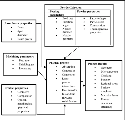
2.2 A scheme of the process
Laser cladding process is influenzed by a lot of processing parameters which are also correlated to each other. Therefore, the process results to be really complex so that the relationship between the variables and the effect of the parametric processing on the process results must be analysed and modeled. In the figure the physical and process variables that affect the clad results are shown.