Unione Europea UNIVERSITÀ DEGLI STUDI DI SALERNO
FONDO SOCIALE EUROPEO
Programma Operativo Nazionale 2000/2006
“Ricerca Scientifica, Sviluppo Tecnologico, Alta Formazione” Regioni dell’Obiettivo 1 – Misura III.4
“Formazione superiore ed universitaria”
Department of Industrial Engineering
Ph.D. Course in Industrial Engineering
Curriculum of Mechanical Engineering
(XVI Cycle-New Series, XXX Cycle)
Tesi di Dottorato in:
ANALYSIS AND ENHANCEMENT OF RESIN
FLOW IN LIQUID COMPOSITE MOLDING
PROCESS
Supervisor
Ph.D. student
Prof. Pierpaolo Carlone
Felice Rubino
Ph.D. Course Coordinator
Prof. Ernesto Reverchon
List of Pubblications
F. Rubino, V. Paradiso, P. Carlone. Flow monitoring of Microwave pre-heated resin in LCM processes. Proceedings of the 20th International ESAFORM2017 Conference on Material Forming, Dublin, Ireland, 26-28th April 2017
Pierpaolo Carlone, Felice Rubino, Valentino Paradiso, Fausto Tucci. Multi-scale modelling and on-line monitoring of resin flow through dual scale textiles in liquid composite molding processes. The International Journal of Advanced Manufacturing Technology (2018).
https://doi.org/10.1007/s00170-018-1703-9. ISSN: 1433-3015
V. Paradiso, F. Rubino, P. Carlone, G. S. Palazzo. Resin flow analysis in a microwave assisted liquid composite molding process. XIII Convegno dell’Associazione Italiana di Tecnologia Meccanica AITEM 2017 Pisa, 11-13 Settembre 2017.
Dragan Aleksendrić, Costanzo Bellini, Pierpaolo Carlone, Velimir Ćirović, Felice Rubino, Luca Sorrentino. Neural-Fuzzy Optimization of Thick Composites Curing Process. Materials and Manufacturing Processes. Under review.
I
Summary
List of Pubblications ... 3 Summary ... I List of Figures... V List of Tables ... XI Abstract ... XII Introduction ... XIII Chapter 1: LIQUID COMPOSITES MOLDING PROCESSES ... 11. Introduction to the Liquid Composites Molding processes ... 1
1.1 Vacuum Assisted Resin Infusion. ... 2
1.2 Resin Transfer Molding (RTM) ... 3
2. Challenging Issues of LCM Processes ... 3
2.1 The Effect of Process Variables on LCM manufactured laminates ... 4
2.1.1 Void Content ... 4
2.1.2 Fibre Reinforcement ... 5
2.1.3 Resin Formulation ... 5
2.2 Strategies to improve the LCM processes ... 5
2.2.1 Injection Strategies for LCM... 5
2.2.2 Cycle Time Reduction Techniques for LCM ... 6
2.2.3 Injection Gate Location... 7
2.2.4 Injection Pressure ... 8 2.2.5 Preform Permeability ... 8 2.2.6 Resin Viscosity ... 8 2.2.6.1 Mould Temperature ... 8 2.2.6.2 Preform Preheating ... 9 2.2.6.3 Resin Preheating ... 9
II
2.2.7 Microwave Processing of Polymers ... 9
2.2.7.1 Microwave Cure ... 10
2.2.7.2 Microwave Preheating ... 11
2.2.7.3 In-Line Microwave Processing ... 11
Chapter 2: MICROWAVE HEATING ... 13
1. Microwave and heating mechanisms ... 14
1.1. Electrical Volumetric Heating ... 15
1.3. Ohmic heating ... 16
1.4. Radio frequency heating ... 16
1.5. Microwave heating ... 17
2. Mechanisms of Microwave Heating ... 18
3. Dielectric properties of materials ... 23
4. Microwave Hardware ... 24
4.1. Microwave Ovens ... 24
4.2. Magnetron ... 25
4.3. Multimode Microwave Ovens ... 27
4.3.1. Single Mode Microwave Ovens... 28
4.3.2. Nomenclature for Single Mode ... 28
4.4. Wave Guides ... 30
4.5. Rectangular Applicators ... 30
4.6. Cylindrical Applicators ... 31
5. The microwave system. ... 31
5.1. Microwave generator ... 32
5.2. Security monitoring device ... 33
5.3. Wave guides and resonance cavity. ... 34
5.4. Using of the microwave generator ... 37
6. Preliminary tests of the in-line microwave heating system ... 39
6.1. Results of the preliminary tests on the first configuration ... 39
6.2. Results of the preliminary tests on the second configuration ... 41
6.3. Results of the preliminary tests on the third configuration ... 45
1. Monitoring of the resin flow front and the resin curing in the LCM
processes. ... 47
1.1 Resistive sensors ... 48
1.1.2. resin flow monitoring... 48
1.1.2. resin cure. ... 51
1.2. SMART-weave sensors ... 52
1.2.1Principle of working ... 55
1.3. Ultrasonic sensors ... 57
1.4. Fiber optic sensors ... 60
1.5. Temperature sensors ... 64
1.4. Pressure sensors ... 66
1.6. Electric time-domain reflectometry (E-TDR) ... 66
1.7. Dielectrical analysis (DEA) ... 71
2. Experimental set-up for monitoring of the resin flow ... 76
2.1 The LCM Mold ... 76
2.2. Dielectric Sensors ... 78
2.3 Pressure Sensors and data acquisition devices ... 80
2.4. Data acquisition devices ... 81
2.5. Materials ... 81
2.5.1 Glass fiber reinforcement ... 81
2.5.2 Resin liquid system ... 82
Chapter 4: EXPERIMENTAL RESULTS ... 83
1. Infusion test of un-heating resin ... 83
1.1. Materials and Experimental procedure ... 83
1.2 Result of the Test 1... 84
1.2. Result of the Test 2 ... 86
2. In-line preheating infusion test: Resonance cavity 1... 90
2.1. Materials and Experimental procedure ... 90
2.1 Experimental results ... 91
3. In-line preheating infusion test: Resonance cavity 2... 95
3.1. Materials and Experimental procedure ... 95
IV
4. In-line preheating infusion test: Resonance cavity 3 ... 100
4.1. Materials and Experimental procedure ... 100
4.2. Experimental results ... 100
BIBLIOGRAPHY ... 105
Appendix A: NUMERICAL SIMULATION OF THE RESIN FLOW ... 113
1. Modelling of the resin flow in the liquid composite molding processes. 113 2. The developed model of the micro-scale resin flow ... 115
List of Figures
Figure I.1: LCM manufacturing processes. Figure I.2. LCM process chain.
Figure I.2. LCM process chain.
Figure I.3. a) Single stream injection system; b) Twin stream injection system.
Figure II.1. Schematic representation of the in-line microwave resin pre-heating system integrated with the LCM process.
Figure II.1. The electromagnetic spectrum.
Figure II.3. Random dipole orientation in uncharged, equilibrium state. Figure II.4. Reorientation of dipoles by an applied electric field. Figure II.5. Dipole vibration due to an alternating electric field.
Figure II.6. Microwave absorption characteristics for conductor, insulator and absorber.
Figure II.7. Schematic of components comprising a domestic microwave oven.
Figure II.8. Typical magnetron for common domestic microwave oven. Figure II.9. Scheme of the conventional magnetron.
Figure II.10. Working fundamentals of a magnetron: a) schematic representation of electric and magnetic fields; b) action of the magnetics forces on the electrons and behavior of the charges.
Figure II.11. Schematic of components comprising a single mode microwave oven.
VI
Figure II.12. Electric field pattern within a TE102 mode rectangular
applicator.
Figure II.13. Electric field pattern within a TM020 mode cylindrical
applicator.
Figure II.15. TE101 mode rectangular applicator.
Figure II.16. TE020 mode cylindrical applicator.
Figure II.17. Microwave generator. Figure II.18. Detector MARTEK 500.
Figure II.19. a) Sketch of the tuner with the location of the three micro-screws; b) wave guide and tuner coupled.
Figure II.20. a) Resonance cavity; b) dimensions of the cavity. Figure II.21. a) Front view b) rear view of the second cavity. Figure II.22. Front view of the third cavity.
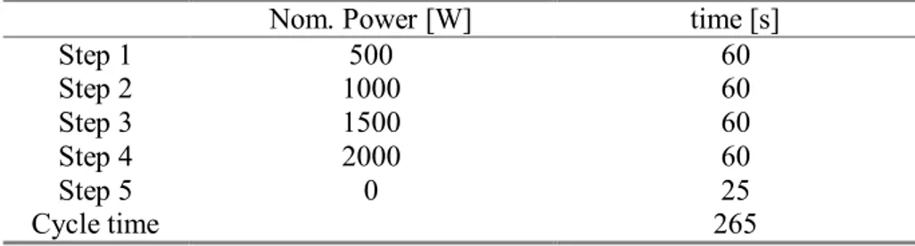
Figure II.23. Example of the measurement of power of the recipe listed in table II.2.
Figure II.24. Set up of the cavity 1 during the preliminary tests.
Figure II.25. Initial, final temperatures and temperature gradients achieved with the first cavity: the showed data are the average values obtained by the several tests performed with the same.
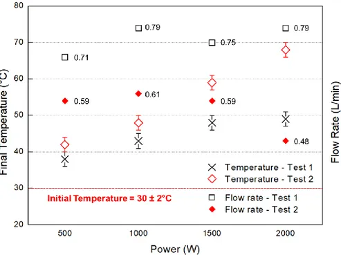
Figure II.26. Cavity 2: experimental set-up of the preliminary testing. Figure II.27. Final temperatures and flow rates measured for Test 1 and Test 2 at different values of nominal power.
Figure II.28. Final temperatures and flow rates for Test 3 at different values of nominal power.
Figure II.29. Parameterized temperature gradients obtained with cavity 3at different values of power and flow rate.
Figure III.1. Circuit for measuring the sensor voltage Vs (scheme of lineal sensor.
Figure III.2. Typical response of lineal-voltage sensor for tow resin system. Figure III.3. Response of a single point-voltage sensor when resin covers the poles.
Figure III.4. Variation of measured voltage during the curing process. Figure III.5. Scheme of a SMARTweave sensor: the resistance network is formed by an excitation-sense pair (referred as sensor plane), with 3 excitation wires and 3 sense wires.
Figure III.6. Representation of the grid-like sensor system: the sensing threads are on a difference plane, so that they are perpendicular but not intersecting each other. A gap is formed between the wires that is the path with minimum resistance. At sensing gaps the resistance is measured. Figure III.7. a) Electrically conductive threads are woven into the
reinforcement fabric; b) the end of each threads can be easily displaced into the fabric in order to allow the clamping and the connection with the measuring device.
Figure III.8. Output voltage profile in a SMARTweave sensor: Resin IN and OUT refer to the voltage monitored at two distinct nodes, the inlet port and the vacuum point of the VARTM apparatus. Points a - c and points b - d refer to the peak values and zero voltage at inlet and vacuum point respectively.
Figure III.9. Representation of the 3D flow of the resin in a VARTM process with center inlet port.
Figure III.10. Response of an ultrasonic sensor: longitudinal sound velocity and relative attenuation versus of processing time trends.
Figure III.11. Ultrasonic measurement of preform impregnation and resin curing stage.
Figure III.12. Set-up of the optical fiber for measuring of the resin flow prior placing within the fiber preform.
Figure III.13a. Behavior of transmitted light in an optical fiber before the resin reaches the sensing point.
Figure III.13b. Behavior of transmitted light in an optical fiber after the resin reaches the bare spot.
VIII
Figure III.14. Typical signal from the optical fiber sensor.
Figure III.15. The optical fibers can be placed on different planes along the thickness of the laminate between the stacked fibers layers. The arrival of the resin on each sensing point is detected and the 3-D path can be
reconstructed.
Figure III.16. Temperature profiles during the resin infusion in a RTM process in two different location of the heated mold: resin inlet point and mold periphery.
Figure III.17. Scheme of the E-TDR technique for flow monitoring: Ei and Er
are the voltage of emitted and reflected waves at a specific location
respectively; Z0 is the characteristic impedance of the line; Zd is the load or
discontinuity impedance.
Figure III.18a. Example of planar E-TDR sensor response: voltage changes versus time trends.
Figure III.18b. Example of planar E-TDR sensor response: resin level measurement.
Figure III.19a. Scheme of E-TDR planar sensor. Figure III.19b. Cross section of two wires sensor.
Figure III.20a. Scheme of the experimental setup for VARTM process. Figure III.20b. Response of the TDR-F sensor to the arrival of resin flow at the sensing locations.
Figure III.21. Schematic representation of a parallel plate dielectric sensor integrated in a RTM tool.
Figure III.22. Dielectric monitoring of the resin fill front: capacitance as function of time.
Figure III.23. Dielectric measurement: a) correlation of dielectric property with the viscosity of the resin; b) correlation between the gelation and the ionic conductivity ; c) vitrification/full cure estimate by means of the dielectric data.
Figure IIII.24. Experimental setup: sensed die and acquisition system used in the flow tests.
Figure III.25. 3D sketch of the sensing mold.
Figure III.26. Drawings of the mold: a) bottom view of upper die; b) top view of lower die; c) Section A-A.
Figure III.27. a) 3D scheme of the designed shielding sensor; b) operating principles of a parallel plate dielectric sensors.
Figure III.28. Pressure sensor: Honeywell SSDRNT100PAAA3. Figure III.29. HM8118 LCR Bridge/Meter.
Figure IIII.1.Experimetnal and numerical results of the Test 1:a ) pressure profiles; b) normalized capacitance and (extra-tow, intra-tow, and total) resin volume fractions; resin volume fraction when the resin arrive at the sensing locations c) S1, d) S2, and e) S3.
Figure IIII.2. Visual and experimental comparison of measure fill-front position.
Figure IIII.3. a) Normalized capacitance profiles, b) microstructure of a sample extracted in the region of the sensor S1, with evidence of the full saturation; c) microstructure of a sample extracted in the region of the sensor S3, with evidence of voids and unsaturated zones.
Figure IIII.4. a) Capacitance (Cs) and dissipation factor (D) during the curing stage at the sensor S1; b) resin degree of cure profiles evaluated in the sensing locations S1, S2 and S3 within the mold.
Figure IIII.5. Experimental set-up for the microwave in-line preheating tests with cavity 1.
Figure IIII.6. Pressure profiles at locations P2 and P3: comparison between the no-heating and preheating infusion tests.
Figure IIII.7. Normalized Capacitance measure by sensor S3: comparison between preheating and un-heating resin infusion test.
Figure IIII.8. Un-heated and preheated resin flow front advancement. Figure IIII.9. Experimental set-up of the microwave in-line preheating tests with cavity 2.
Figure IIII.10. Result of the Test A: resin flow front progression for un-heating and preun-heating trials.
X
Figure IIII.11. Result of the Test B: a) resin flow front progression for un-heating and preun-heating trials; b) image of the composite laminate
manufactured; micrographies of the laminate cross section in different location c) S1 and d) S3.
Figure IIII.12. Experimental set-up of the microwave in-line preheating tests with cavity 3.
Figure IIII.13. Microwave heating strategy.
Figure IIII.14. Resin flow front progression for un-heating and preheating trials.
Figure A.1. Microscopy observation of the manufactured laminates and 3D solid model of the representative volume element.
Figure A.2. Schematic of the domain and the applied boundary conditions. Figure A.3 Streamlines of the inter-to flow in the representative volume element.
Figure A.4. Sink term variation as a function of the saturation. Figure A.5. Sink term as a function of the inter-tow liquid pressure. Figure A.6. Results of the regression analysis for the angular coefficient m(s): a) third order polynomial model, b) fifth order polynomial model, c) seventh order polynomial model, d) exponential model.
List of Tables
Table II.1. Constituents of microwave generator system.
Table II.2. Example of the power cycle executed by the microwave generator.
Table II.3. Average ΔT at different power level achieved with the first cavity and for a heating liquid flow rate of 7.8 x 10⁻³ l/s.
Table II.4. Result of the heating trials for the Test 1 and Test 2. Table III.1. Properties of the Polyester Resin.
XII
Abstract
The research activity was devoted to the study of the composite materials manufacturing processes. In particular, the liquid composite molding (LCM) processes were the object of the performed study. In recent years LCM processes have gained a widespread diffusion in different industrial fields, from civil to automotive and aerospace due to their several advantages compared to the conventional autoclave processes. However, some disadvantages related to a not uniform preform impregnation due to a local variation of the preform permeability, fibers bundles misalignment, that would results in dry zones or matrix richer areas, affect the LCMs limiting their usage in industrial full scale. Other limits are due to a limited pressure driving force as well as a reduced pressure compaction influencing the final volume fraction achievable with detrimental effects on the mechanical properties of the composite material product. A more deep knowledge of the phenomena involved in the manufacturing of the composite materials are required to implement proper control action on the parameters (e.g. pressure, resin flow rate, thermal cycle as well as inlet/vent locations) to optimize the process.
In order to improve the impregnation of the preform and reduce the time required to fully fill the mold cavity an in-line microwave preheating system was developed. The aims was to couple a microwave generator upstream the LCM mold to heat up the resin prior the entry into the mold. Indeed, the temperature increasing reduces the liquid viscosity allowing the resin to flow more freely through the dry preform. To perform a thorough study on the effectiveness of the proposed approach a laboratory scale apparatus for liquid composite molding processes was designed. The system was instrumented with ad-hoc designed sensors to monitor the resin flow during the process. Cheaper dielectric sensors are designed, produced and installed on the mold. A numerical model was also developed to simulate the resin flow through the fibers preform. The numerical model proved to able to deal with the dual-scale nature of the textile preform commonly used in the LCMs, that are characterized by two different regions (inter- and intra-tow) with different values of permeability. The numerical outcomes were also used to validate the data obtained from the dielectric sensors. They demonstrated to be able to monitor the both the impregnation and the saturation of the fiber preform.
The developed microwave heating system proved to be effective to both reduce the total infusion time as well as improve the wetting of the fibers, achieving a more uniform impregnation with a limited amount of residual voids.
Introduction
Liquid Composite Molding (LCM) processes are popular composite manufacturing methods which are used in the civil, aerospace, and automotive industry due their several advantages compared to other conventional production techniques like Autoclave processes. They include (but not limited to) net-shape production, high injection pressures, moderately low cycle times, simple tooling requirements as well as low VOx emissions to produce fiber reinforced polymer composites (FRPC). LCM have proved to be efficient for producing low-cost, high-quality and complex shaped composite parts. The LCM processes use a tailored stack of fibre reinforcements also known as preforms. Preforms, conventionally made of glass, carbon or Kevlar fibers, are usually manufactured from woven or stitched mats multiaxial orientated textile structures, or three dimensional weaves. The preforms can be produced exactly to fit the needs of the parts, designing the orientation and the arrangement of the fibers. Generally, it is possible to manufacture near net-shaped preforms and subsequently FRPC-parts. The term LCM summarizes different techniques, which present the same characteristics. Some of the most widespread LCM processing techniques are Vacuum Assisted Resin Infusion (VARI), and injection, e.g. Resin Transfer Molding (RTM), processes. Despite of the different developed techniques, the LCM processes essentially consists in several common stages. Initially the fiber preform is manufactured, as mentioned above. After the preform-manufacturing step, the preform needs to be saturated and impregnated during composite processing with a liquid matrix, a mixture of a polymeric resin and hardener. The matrix system replaces the air in the dry preform. The LCM processes start with placing the preform in a mold. The next step includes mold closing and preform compaction. After ensuring that the mold is closed the matrix impregnates the reinforcing structure. After the curing phase the part can be demolded and post processed. Combinations of composite manufacturing techniques, i.e. Vacuum Assisted Resin Transfer Molding (VARTM), are possible and used. Large scale components result in long distance flow paths determining several, e.g. long cycle times and increasing resin viscosity. To overcome these issues some techniques are developed, e.g. SCRIMP or ARTM, to improve the impregnation of the reinforcing structure. To date the LCM processes are still considered as “emerging” technologies compare to the well-established autoclave process that ensure high standard quality products, being their usage limited on an industrial full scale. Indeed, disadvantages affect the LCMs that can occur during processing along the whole process
XIV
chain. Several effects can be result of local variations of preform permeability, due to local differences in preform porosity or preform architecture. Race-tracking is a term which has been used to describe the deformation of the resin flow front. This effect can occur on edges, corners and other complicated areas in a mold. In order to eliminate these effects a careful mold design and a near net-shaped preform is needed. Low preform compaction and/or a high injection pressure can result in the effect of fiber wash out. Defects like matrix rich areas, bent or curved fibers and fiber buckling are leading to rim regions for those a mechanical post treatment, e.g. trimming, is necessary.
The effect of high speed processing on the mechanical properties and surface finish of RTM laminates has been investigated by several authors. Void content, reinforcement properties, and resin formulations have been shown to affect the quality of the laminates
Different strategies to improve the LCM processes in terms of improving of the products quality as well as reducing of cycle times and costs. These strategies can be related to different aspects of the process, such as the employed materials, tools as well as infusion/injection strategies.
The present research activity was devoted to the investigation of “In–line Resin Preheating” techinique to improve the wettability of the fiber preform as well as reduce the overall impregation time. Preheating of the resin system has a dual effect: it lowers the resin viscosity to facilitate flow and reduces the amount of heat that must be supplied by the heating apparatus to initiate polymerization. These factors promote reductions in both the impregnation and cure phases, resulting in an overall cycle time reduction. An in-line microwave resin preheating system basically consists in the heating of the resin during injection/infusion by means of a microwave system the provide the required heat to increase the resin temperature up to desired value. This technique is able to yield a true cycle time reductions, because it allows saving the time required to heat the resin before injection/infusion or flushing of the injection system after molding in the batch solution. The main challenge in the usage of in-line preheating system is related to the thermally sensitive nature of the thermosetting resin employed in the LCMs. A proper design of the microwave applicator is required to evenly heating the material. Indeed, under laminar flow conditions (that is the typical flow regime in the case of high viscosity liquids like the thermosetting resins) maximum velocity is developed along the flow axis, decreasing to zero at the wall of the transporting pipe. Uniform heating across the pipe diameter would cause an excessive heating of the liquid boundary layers at the pipe wall, with inadequate heating along the flow axis. It could results in a premature curing of the resin at the pipe wall or event the burning if the degradation temperature is exceeded.
The aim of the research activity was to investigate and developed a microwave system, including the microwave generator and the proper applicator, to preheat the resin prior the injection into the mold.
The study of the optimal solution has required the testing of different configuration of the microwave system, varying the geometry of resonance cavity and tuning the proper power-time cycle of the microwave source, as well as the simultaneusly development of an sensing system integrated within the mould to monitor the composite manufacturing process. It also included the building up of a suitable numerical model able to predict the behavior of the resin during the infusion stage.
A laboratory scale sensing apparatus was designed and developed to reproduce a LCM manufacturing processes. The experimental system consisted in an aluminum mold with an inner cavity 3 mm deep. The little thickness of the manufacturable laminate and its bigger in-plane dimensions allow reproducing a monodimensional resin flow through the fiber bulk. The mold was instrumented with dielectric and pressure sensors. A video-camera was also mounted on the upper half-mold to perform a visual observation of the resin flow advancement indipendently of the experimental data provided by the sensors. The data from the pressure sensors coupled with the outcomes form numerical simulations were employed during a preliminary experimental campaign to validate the measurements obtained from the developed dielectric sensors. To this purpose, unreactive liquid system was employed and distinct process parameters configurations were adopted. The microwave system was carefully tested in order to evaluate the best configuration: preliminary heating tests were performed employing different resonance cavities and varying the flow rate within the pipe. The tests were needed to asses the proper microwave power and the exposition time of the resin to the electromagnetic field. The microwave system was set to provide a variable power during the infusion stage according to the decreasing resin flow rate.
In the first chapter a briefly description of the LCM processes is reported. The main features, drawbacks as well as the improvement strategies investigated in the recent years are debated. The second chapter is devoted to the microwave system. The main characteristics of a microwave generator and the working fundamentals are described. The developed laboratory-scale apparatus is also presented. The third chapter is focused on the monitoring system. The different techniques employed in the manufacturing of the composite materials are reported. Then, the dielectrical analysis fundamentals and the applications in LCM processes are described. The experimental apparatus, including mold, sensors and data acquisition system, is detailed in this chapter. In the four chapter the main results were reported and discussed. Then, proper conclusions about the research activity were drawn and debated.
1
Chapter 1: LIQUID
COMPOSITES MOLDING
PROCESSES
1. Introduction to the Liquid Composites Molding processes
Liquid Composite Molding (LCM) processes are popular composite manufacturing methods which are used in the civil, aerospace, and automotive industry due their several advantages compared to other conventional production techniques like Autoclave processes. They include (but not limited to) net-shape production, high injection pressures, moderately low cycle times, simple tooling requirements to produce fiber reinforced polymer composites (FRPC) as well as low VOx emissions. LCM have proved to be efficient for producing low-cost, high-quality and complex shaped composite parts (Bickerton & Advani, 1999; Sozer, Bickerton & Advani, 2000). The LCM processes use a tailored stack of fibres reinforcements also known as preforms. Preforms, conventionally made of glass, carbon or Kevlar fibers, are usually manufactured from woven or stitched mats multiaxial orientated textile structures, or three-dimensional weaves (Bickerton & Advani, 1999). The preforms can be produced exactly to fit the needs of the parts, designing the orientation and the arrangement of the fibers. Generally, it is possible to manufacture near net-shaped preforms and subsequently FRPC-parts (Grieser, Rieber & Mitschang, n.d.; Weimer et al., 2000b, 2000a). LCM processes are usually completed in several stages. Initially the fiber preform is manufactured, as mentioned above. After having finished the preform manufacturing step, it needs to be saturated and impregnated with a matrix system, a mixture of a polymeric resin and hardener. The matrix system replaces the air in the dry preform. The LCM processes start with placing the preform in a mold. The next step includes mold closing and preform compaction. After ensuring that the mold is closed, the matrix impregnates the reinforcing structure. After the curing phase the part can be demolded and post
2
processed (Bickerton & Advani, 1999; Kendall et al., 1992). The term LCM summarizes different techniques, which present the same characteristics above described. Some of the most widespread LCM processing techniques are Vacuum Assisted Resin Infusion (VARI), and injection, e.g. Resin Transfer Molding (RTM), processes (see figure 1).
Figure I.1: LCM manufacturing processes (Schledjewski & Grössing, 2017) Combinations of composite manufacturing techniques, i.e. Vacuum Assisted Resin Transfer Moulding (VARTM), is possible and used. Large scale components result in long distance flow paths determining several, e.g. long cycle times and increasing resin viscosity. To overcome these issues some techniques are developed, e.g. SCRIMP or ARTM, to improve the impregnation of the reinforcing structure (Becker & Mitschang, 2015).
1.1 Vacuum Assisted Resin Infusion.
The VARI process is a simple and cost-effective technique to impregnate the dry reinforcement with a liquid resin system. A predefined preform is draped in a one-sided mold. It is covered by a peel ply, a distribution medium (plastic tubes and spiral hoses) and a vacuum bag. Around the mold, the vacuum bag is fixed with sealant tape, which also seals the cavity. By applying the vacuum within the vacuum bag, the preform gets compacted by ambient pressure. After opening a valve in the infusion tube, the resin flows under the vacuum bag and infiltrates the reinforcing bulk. After a complete impregnation, the valve is closed and the matrix system cures. The curing process can be aided by using a curing oven or a heating system. The maximum part sizes that can be handle with the VARI are limited by the maximum pressure difference of ∆P< 1 bars per injection points that can be
3 applied. Flow distribution medium and more injection points, placed along the part length are, are usually employed to overcome these limits, preventing the detrimental premature gelification of resin prior the complete impregnation of preform, and allow the infiltration of larger reinforcing structures, e.g. rotor blades of a wind energy plant. Different infusion strategies, like point, ring and line gates, make possible to control the infusion time and the flow impregnation progression. The mold manufacturing and the used equipment for a VARI are due to the requirements comparatively cost- effective. The process limitations are low fiber volume contents, generally < 50%, a higher amount of voids due to the limited compaction action exerted by the ambient pressure, low quantities about up to 2000 parts/year as well as thickness restrictions of the part (Schubel, 2010; Modi et al., 2009).
1.2 Resin Transfer Molding (RTM)
The RTM process, in contrast to the VARI process, utilizes a closed mold for processing FRP-parts. The two mould halves are usually mounted on a mold carrier, which ensures, with its closing force, a closed cavity during fluid injection. In contrast to VARI, no additional consumables are required. After placing the preform in the mould cavity the mold is closed, the preform is compacted to the final part thickness, and the liquid resin system is injected into the mould by a designed pressure or mass flow. After a successful impregnation, the mold halves can be heated in order to accelerate the curing reaction. The process cycle time depends on the part size, the part geometry, the part complexity and of course the injection strategy. As a result of full automated RTM processes, process cycle times between 5 – 25 minutes and a quantity of > 50000 per year can be reached. The reinforcing structure has a huge and direct impact on the matrix flow behavior in the mold. The filling strategy i.e. the position of the injection and vent points of the mold, play a key role for the process success. Thus, the mold filling behavior should be considered during the mold design and mold development phase using numerical filling simulations in order to eliminate the very expensive trial-and-error procedure. The investment costs (a mold carrier, an injection unit, and a complex two-part mold) for RTM processing are more expensive compared to the VARI process. (Kendall et al., 1992).
2. Challenging Issues of LCM Processes
Disadvantages for LCM can occur during processing along the whole process chain (see figure 2). Several effects can be result of local variations of preform permeability, due to local differences in preform porosity or preform architecture. The Race-tracking describes a deformation of the resin flow front that can occur on edges, corners and other complex areas in the mold. In order to eliminate these effects a careful mold design and a near net-shaped preform
4
is needed (Bickerton & Advani, 1999; Grieser, Rieber & Mitschang, n.d.). Low preform compaction and/or a high injection pressure can result in the effect of fiber wash out. Defects like matrix rich areas, bent or curved fibers and fiber buckling are leading to rim regions for those a mechanical post treatment, e.g. trimming, is necessary (Grieser, Rieber & Mitschang, n.d.).
Figure I.2. LCM process chain
2.1 The Effect of Process Variables on LCM manufactured laminates
The effect of process variables on the mechanical properties and surface finish of RTM laminates has been widely investigated. Void content, reinforcement properties, and resin formulations have been shown to have a significant influence on the quality of the laminates.
2.1.1 Void Content
Two mechanisms have been identified that promote voids formation in composites (Lundstrom & Gebart, 1994). Gas discharge into the resin due to the chemical reaction between the resin and catalyst is one cause of voids. A second mechanism for void formation is the mechanical entrapment of air during mold filling. This situation occurs when the longitudinal resin flow front (macro flow) exceeds the lateral flow of resin into the fiber bundles (micro flow). Macro flow is responsible for displacing the air within the reinforcement (wet- through), while micro flow allows the resin to wet and bond with the individual fibers (wet-out). Lundstrom and Gebart (Lundstrom & Gebart, 1994) stated that void content dropped significantly when a vacuum was drawn at injection, or pressure was applied during cure. Patel et al. (Patel,
5 Perry & Lee, 1991) showed that low injection pressures increased the tensile strength of unidirectional reinforced polyurethane laminates. They attributed this result to improved micro flow for better fiber wet-out during the longer impregnation phase. These researchers also recorded higher tensile strengths for high temperature moldings as a result of enhanced wet-out due to lower viscosity, and greater chemical bonding between the fiber sizing and the resin.
2.1.2 Fiber Reinforcement
Young and Tseng (Young & Tseng, 1994) related fibre configuration to the degree of fibres wetting. They concluded that large bundle sizes in bidirectional woven roving reinforcements created flow channels between the bundles. Low filling speeds were necessary to allow sufficient wet-out without rapid advancement of the flow front down the channels. Fabrics with smaller fiber bundles could be filled faster with improved fiber wet-out. Moldings produced with unsaturated polyester resin and CFRM reinforcement coated in an unsaturated polyester sizing agent, produced the highest strength laminates due to good bond formation at the interface.
2.1.3 Resin Formulation
Lindsey (Lindsey, 1994) showed that increasing the catalyst concentration from 1 % to 3% (by mass) in polyester resin not only reduced cycle times, but also improved the strength of CFRM reinforced laminates. Furthermore, the addition of calcium carbon filler to polyester resin was determined to affect laminate mechanical properties. Rudd et al. (Rudd & Kendall, 1992) showed that increasing the filler content up to 50 phr increased the laminate mechanical properties, with decreases in properties occurring at higher concentrations
2.2 Strategies to improve the LCM processes
2.2.1 Injection Strategies for LCM
Figures I.3 illustrates the single stream and twin stream injection techniques typically used in liquid composite molding processes.
6
Figure I.3. a) Single stream injection system; b) Twin stream injection system.
SRIM is constrained to twin stream injection by nature of the chemically reactive resin systems. The resin and hardener streams remain separate until impingement mixing near the injection gate. Most RTM resin systems are thermally activated making twin stream injection possible, but not essential. The principal advantage of a twin stream delivery system is that the resin and catalyst components are non-reactive, and therefore, insensitive to temperature until mixing at the injection gate. Preheating large volumes of each component to increase resin reactivity is possible using simple conduction heating devices, although precise temperature control would be difficult to achieve. Highly reactive resin systems can be used with the qualification that the mold is filled, and fiber wet-out is sufficient, before the resin gels. Twin stream injection systems prevalent in industry for producing large components commonly are driven by reciprocating pumps. Pressure variations occur during the pump stroke using these systems. Karbhari et al. (Danideh & Sadeghzadeh, 2013)(Karbhari et al., 1992) showed that decreasing the length of the pump stroke reduced the pressure variations and improved the mechanical properties of the laminate. Pulsed delivery of the individual streams leads to inaccurate dosing and has prompted the following investigators to implement constant volume, lance driven injection systems.. Measured resin quantities can be mixed before molding and stored in a pressure vessel. Delivery of the resin into the mold under constant pressure results in cavity pressures that are typically lower than for a reciprocating pump system (Kendall et al., 1992). The primary disadvantage of single stream injection is that the pre- mixed resin is thermally sensitive. Resins with low reactivity at ambient temperature must be used to prevent premature cure within the storage vessel before injection has been completed. Single stream systems are dependent upon heat to initiate the polymerization reaction. Normally, heat is provided by the mold. Thermal quench at the injection gate due to cold resin entering the hot mold hinders the heat transfer capacity of the mold and extends cycle time. Preheating the resin to reduce mold quench is an obvious solution, however, the thermal sensitivity of the resin warrants special treatment to prevent premature cure within the injection system (Hill, 1993).
2.2.2 Cycle Time Reduction Techniques for LCM
Several authors have identified the process variables that affect cycle time and have suggested techniques to reduce this time. The interaction between process parameters makes isolation of a single factor difficult. Karbhari et al. (Karbhari et al., 1992) performed a Taguchi study to quantify the interaction of several molding parameters including reinforcement types, mold
7 temperature, and injection strategies. They found that a short pump stroke had the greatest influence on the tensile, flexural, and shear properties of composites. From a broader standpoint, their work proposed a methodology to define a robust processing window for RTM. Other investigators have varied a single parameter then analyzed the resulting changes to the process. Cycle time comprises both the impregnation and cure phases. Most process models separate the phases into two separate events for simplicity (Kendall et al., 1992) Resin flow during impregnation has been described by the Darcy relationship:
𝑄 =𝐾𝐴 𝜇
𝑑𝑝
𝑑𝑥 (I.1)
Where the resin flow rate (Q) is proportional to the preform permeability (K), the flow area (A), and the pressure gradient (dp/dx), but inversely proportional to the resin viscosity (p). Typically, reductions in the impregnation time will promote overall cycle time reductions. The cure phase consists of heat transfer into the stationary resin at the end of impregnation, followed by heat generation from the exothermic polymerization reaction. The rate of this reaction (dα/dt) is often expressed by the Kamal and Sourour expression (Kamal & Sourour, 1973):
𝑑𝛼
𝑑𝑥= (𝑘1+ 𝑘2𝛼)
𝑚(1 − 𝛼) (I.2)
Where α is the degree of cure and the kinetic constants are k1 and k2. The
end of the cure phase (and cycle time) can be defined as being equal to a pre-established percentage of conversion. Several RTM process variables that influence cycle time are discussed below.
2.2.3 Injection Gate Location
Gebart et al. (Gebart, Gudmundson & Lundemo, 1992) determined that the impregnation time was influenced strongly by the injection gate location. Three injection techniques were used to fill a square plaque mold including center pin gate injection, edge, and peripheral gate injection. Peripheral injection was approximately three times faster than edge injection and ten times faster than center injection as a result of a larger flow area for the resin. Lower impregnation times were assumed to result in proportional reductions in the cycle time. Rudd and Kendall (Rudd & Kendall, 1991) reported similar results for equivalent gating strategies. Peripheral and edge injection also reduced mold quench by increasing the area of the mold being subjected to cold incoming resin. Local cooling was limited, and the overall cycle time was reduced (Rudd & Kendall, 1992). However, the authors concluded that the pressure on the mold was greatest during peripheral injection, and least for center injection. Overfilling the mold increased the hydrostatic pressure and
8
caused significantly higher in-mold pressures during exotherm. High pressure, particularly in shell molds, could result in resin leakage, clamp damage, localized mold distortion, or part thickness variations.
2.2.4 Injection Pressure
Increasing the pressure of a constant pressure injection system reduces the impregnation time. This results from an increased forcing pressure gradient is countered by a higher resin viscosity as in-mold heating of the flowing resin is decreased. Rudd et al. (Rudd, Owen & Middleton, 1990) concluded that the injection pressure affected the impregnation time to a greater extent than the cycle time since thermal quench was distributed over a larger portion of the mold. One disadvantage of high injection pressure is mold deflections. Selection of injection pressures beneath the mold damage threshold has been controversial. Some manufacturers argued that a low injection pressure improves fiber wet-out, while others claimed high pressure is necessary to purge air from the mold (Young & Tseng, 1994)
2.2.5 Preform Permeability
Preform permeability is governed by fiber architecture and volume fraction. Highly permeable preforms reduce the restriction of resin flow, lowering the impregnation time. Peterson and Robertson (Peterson & Robertson, 1991) determined that for a given fiber volume fraction, increasing the fiber diameter increased reinforcement permeability, reducing the impregnation time. Increasing fiber bundle diameter also increased the resin flow rate, but void formation was a dominant effect.
2.2.6 Resin Viscosity
Reducing resin viscosity improves resin flow through the preform, in turn lowering the impregnation time for constant pressure injection systems. Resin viscosity can be reduced by several means including mold temperature increases, preform preheating, and resin preheating. The influence of each of these parameters is described below.
2.2.6.1 Mold Temperature
Increasing the mold temperature heats the resin to a greater extent as it flows through the mold, reducing viscosity and shortening the impregnation phase. In addition, the cure phase can be reduced significantly by increasing the mold temperature since gel times across the mold are reduced. Thermal quench occurs when cold resin enters the hot mold, cooling the preform and mold. Kendall (Rudd & Kendall, 1992) determined that the overall cycle time was dictated by thermal quench at the injection gate. Perry et al. (Perry et al., 1992) investigated the relationship between mold material and cycle time. The
9 use of high thermal conductivity molds such as aluminum and chromed copper, shortened the cycle time compared to epoxy tooling, as a result of faster heat up after thermal quench, and a more even temperature distribution across the mold. In addition, peak exothermic temperatures were lower in the high conductivity molds since heat could be removed more effectively from the mold surface
2.2.6.2 Preform Preheating
Preheating the preform to the mold temperature (110° C) prior to injection under constant pressure was shown to reduce the impregnation time by 15% and the cycle time by 40% compared to molding produced with a colder preform (50°C) (Rudd, Owen & Middleton, 1990). The warm preform lowered the resin viscosity for improved flow, contributing to a reduction in impregnation time. Furthermore, the temperature within the mold cavity at the end of impregnation was greater so that the time to heat the quenched laminate back to mold temperature was reduced.
2.2.6.3 Resin Preheating
Preheating lowers the resin viscosity to facilitate flow, and reduces the amount of heat that must be supplied by the mold to initiate polymerization. These factors promote reductions in both the impregnation and cure phases, resulting in an overall cycle time reduction. Several techniques have been used to preheat the resin. Rudd et al. (Rudd, Owen & Middleton, 1990) fitted a heater jacket to the resin storage vessel to raise the temperature from 20°C to 55°C. A molding produced with preheated polyester resin reduced both the impregnation and cycle times by 20%. Hill (Hill, 1993) produced a similar result by preheating polyester resin in a domestic microwave oven to 60°C for a 50% reduction in cycle time. However, these cycle time reductions did not include the time required to heat the resin before injection or flushing of the injection system after molding. Subsequently, Hill developed a sophisticated in- line microwave resin preheating system that yielded true cycle time reductions, since the resin was heated during injection. Using this microwave system, a 35% reduction in cycle time by preheating resin to approximately 46°C was demonstrated.
2.2.7 Microwave Processing of Polymers
The time required to heat the stationary thermosetting resin at the injection gate to the activation temperature of the initiator dominates the cycle time (Rudd, Owen & Middleton, 1990). Industrial acceptance of microwave processing over conventional heating methods is increasing since microwave heating features high power density applicators, improved thermal control,
10
and reduced equipment size. Microwave processing is common in the rubber industry where extruded rubber is heated to the vulcanization temperature in a microwave oven in a continuous process. The food preparation industry has developed continuous microwave heating processes with the additional advantages of greater sanitation and pasteurization capabilities (Metaxas & Meredith, 1983). Industrial microwave systems dedicated to FRP processing are less developed although research in the following areas has been reported.
2.2.7.1 Microwave Cure
An early application of microwave cure in the composites industry was presented by Strand (Strand, 1980) who showed a thirty-fold reduction in the cure time of an iron- oxide filled epoxy resin. Glass fiber reinforcement impregnated with the resin was placed in a microwave transparent mold. The mold was located in a multimode oven for curing. The dielectric loss factor of the epoxy mold was relatively low compared to uncured liquid epoxy resin so that it absorbed only a small amount of the microwave power. The uncured resin, however, readily absorbed the microwave power and the cure time was reduced. Strand used the same technique to cure a polyester resin. Boey et al. (Boey, Gosling & Lye, 1993) modified an autoclave for microwave curing of glass reinforced epoxy components. Laminates were placed in a single-sided mold, vacuum bagged for consolidation, then placed in an autoclave that had been sealed to prevent microwave leakage. Microwaves were emitted from a horn directed towards the composite. A PC controlled stepper motor moved the horn along an X-Y plane over the surface of the component. Dosage levels were controlled by altering the microwave power or the traversing speed of the horn so that laminates of varying thickness could be cured more evenly. The addition of glass reinforcement into neat resin systems causes no microwave processing difficulties since most glasses are virtually transparent to microwave energy. However, use of carbon fiber reinforcement complicates microwave processing. Typically, the carbon fibers are longer than the microwave wavelength so that reflection occurs when the fiber are placed parallel to the electric field, and absorption when the fibers are oriented perpendicularly. Lee and Springer (Woo Il Lee & Springer, 1984) considered this to be a limitation for microwave processing of structural components since the carbon fibers would have a multidirectional orientation. Subsequently, Drzal et al. (Drzal, Hook & Agrawal, 1991) determined that the heated carbon fibers initiated cure in the epoxy by thermal conduction, with the advantage of improved interfacial bonding. The effects of microwave processing on laminate properties is disputed. Yue and Boey (Boey & Yue, n.d.) measured a 50% increase in the tensile modulus of epoxy by microwave curing as opposed to conduction curing. Hawley et al. (Hawley & Wei, 1991) claimed improved flexural properties for epoxy composites but did not quantify their results. Marand et al. (Marand, Baker & Graybeal, 1992)
11 concluded that microwave processing led to a lower degree of cure and was expected to result in inferior mechanical properties.
2.2.7.2 Microwave Preheating
Thermoplastic materials that do not possess a dipolar structure normally can not absorb microwave power. However, thermoplastics such as polyethylene and polyphenylene sulfide have been preheated by mixing a microwave absorbing additive (N-ethyl toluenesulfonamide) into the matrix. The additive promotes localised heating to allow processing of the thermoplastic without degrading its mechanical properties (De Meuse & Ryan, 1993). Costigan and Birley (Costigan & Birley, 1988) batch preheated SMC in a multimode oven prior to compression molding. The viscosity of the charge was reduced and flowed more readily, implying that a lower capacity press could be used. Furthermore, the temperature drop across the mold was reduced, lowering cycle times. The tensile strength of the laminate increased proportionally with the charge preheat temperature. The authors attributed this result to less fiber reorientation, more even cure, and reduced thermal stresses.
2.2.7.3 In-Line Microwave Processing
Methven and Ghaffariyan (Methven & Ghaffariyan, 1992) developed a cylindrical applicator to process glass FRP reinforcement bars for concrete by pultrusion. Heat was transferred efficiently to the resin so that the die length could be reduced with a corresponding decrease in frictional forces. As a result the glass fiber reinforcement could be pulled through the die more rapidly, and larger cross section parts could be produced, compared to the conventional system. In-line preheating of thermally sensitive liquids is more complex. Under laminar flow conditions, maximum velocity is developed along the flow axis, decreasing to zero at the wall of the transporting pipe. Uniform heating across the pipe diameter would heat the boundary layers at the pipe wall excessively, with inadequate heating along the flow axis. Apart from study of Hill and Johnson, (Hill, 1993; Johnson, 1995), no microwave preheating system for thermally sensitive resins has been discovered in the literature.
13
Chapter 2: MICROWAVE
HEATING
The purpose of this research was to estimate and characterize the effects of resin microwave preheating on the resin infusion process and quantify the resulting changes in terms of infusion time required and level of preform saturation. The idea consists in coupling a microwave system with the laboratory scale apparatus for the composite resin infusion manufacturing process. The microwave system, comprising microwave generator, wave-guides and applicator, heat up the liquid resin coming for the vessel prior entering into the mold. The resin flow pass through the resonance cavity within a PTFE tube that is transparent to the microwave, so that it does not alter the electro-magnetic field. The temperature of the resin increases and consequently a reduction of the viscosity is experienced. It allows the liquid resin to flow more freely through the fiber preform
Figure II.1. Schematic representation of the in-line microwave resin pre-heating system integrated with the LCM process.
14
This chapter briefly described the materials, the equipment and methods adopted to perform the study. The resin infusion system and the instruments used to delineate between the effects of ordinary process and resin preheating are defined. The hardware employed to integrate the resin preheating system into the resin infusion cycle is described. The methods adopted to develop and evaluate the performance of the preheating system is detailed and discussed.
1. Microwave and heating mechanisms
Microwave heating as an industrial process is a technique which was originally conceived about sixty years ago. The advent of the magnetron during the Second World War presented engineers and scientists a unique challenge to put such a device for generating microwaves into successful use. The main challenge to face was related to the lack of appropriate equipment and the lack of data on dielectric property of the materials, which were considered as candidates for microwave heating. During the late forties and early fifties, many efforts was paid to obtain reliable data on material properties. The work of von Hippel on the properties of many organic and inorganic materials in the frequency region 100 < f < 1010 Hz has formed a
solid basis for the establishment of radio frequency and microwave energy techniques in industry (Von Hippel, 1995). In addition, there have been significant developments on the design of magnetrons, power supplies and ancillary equipment, giving greater reliability to this new technique. The engineering aspects of many applications in terms of scale-up, continuous operation, automatic control, etc., have considerably improved since the original days.
In recent years, interest has grown rapidly in extending the application of microwave energy to process new engineered materials, including ceramics, polymers, composites, and chemicals due to the many benefits of microwave processing, the increased knowledge about the fundamentals of the microwaves and their interaction with the materials as well as the availability of novel production techniques.
The use of microwave energy provides clean, rapid, and efficient heating over a wide range of temperatures (up to 2000 °C or more), as well as a higher flexibility over conventional processing methods. Microwave processing is fundamentally different from conventional heating because electromagnetic energy is directly transferred to and absorbed by the processed material. This energy is converted into heat within the material and thus provides energy savings by eliminating the large thermal mass of conventional furnaces. Because of microwaves are a penetrating radiation, materials exposed to them are heated from the inside and they can be heated more uniformly than conventionally heated materials without high temperature gradient between the surfaces and the core of the material. This is particularly desirable for low
15 thermal-conductivity materials, such as polymers and ceramics. This method enables internal moisture to be removed from wet solids, as well as internal gases generated during binder burnout. Because of microwave heating mechanisms are different from conventional heating processes, processing equipment and processing conditions present new challenges that have to be dealt with.
It is important to define the frequency ranges for which the terms microwave and radio frequency will be subsequently used (see figure II.2). At frequencies below 100 MHz, where conventional open wire circuits are used, the technique of industrial processing will be referred to as radio frequency heating. At microwave frequencies (above 500 MHz), wired circuits cannot be used and the power is transferred to the applicator containing the material to be processed in waveguides. This technique will be referred to as microwave heating. In between, there exists a diffuse regime where the equivalent circuit representation for the two techniques blend together and become difficult to differentiate.
Figure II.1. The electromagnetic spectrum
1.1. Electrical Volumetric Heating
By electrical means, volumetric heating is possible wherein all the infinitesimal elements constituting the volume of a workload are each heated individually, ideally at substantially the same rate. The heat energy injected into the material is transferred through the surface electromagnetically, and does not flow as a heat flux, as in conventional heating. The rate of heating is no longer limited by thermal diffusivity and surface temperature, and the uniformity of heat distribution is greatly improved. Heating times can often be reduced to less than 1% of that required using conventional techniques, with effective energy variation within the workload less than 10% (Meredith, 1998). Any material can be heated directly by electrical volumetric heating provided that it is neither a perfect electrical conductor nor a perfect insulator, implying that the range extends from metals to dielectric materials which
16
could be considered quite good insulators. No single electrical techniques is effective in all cases and there are four methods used in practice, classified by the effective electrical resistivity and physical properties of the work piece.
1.2. Conduction and induction heating
These processes are used for heating metals with low resistivity and involve passing a heavy current through the workload to cause RI2 heating.
The current may pass between physical electrical connections to the workload (conduction, or resistance, heating). The electrical frequency used ranges from direct current (DC) to 60 Hz. Alternatively the workload may form the secondary of a step-down transformer in which the induced electric and magnetic field (EMF) causes the References heating current to circulate (induction heating), with electrical frequency of 50 Hz to about 30 kHz.
1.3. Ohmic heating
Ohmic heating is a conduction heating technique for liquids and pumpable slurries; it consists of equipment for passing an alternative current through the liquid between electrodes. Aqueous solutions, in particular, are almost always sufficiently conductive to permit a high power density to be dissipated, because dissolved salts provide ions as charge carriers. Ohmic heating invariably uses a power-frequency supply (50-60 Hz) and is extremely efficient as a converter of energy to heat in the workload, with efficiency of conversion over 95%.
1.4. Radio frequency heating
When the workload has high resistivity, the voltage required to pass sufficient current for a practical power-dissipation density becomes prohibitive at the low frequency used for conduction heating. This problem can be overcome by increasing the frequency to the range 1-100 MHz, most often 27.12 MHz, one of several internationally agreed frequency for the purpose. Typical applications are plastics (welding and forming), wood (seasoning and gluing), textiles, paper and board (drying), food (post-baking/drying) and ceramics (drying). The workload is placed between electrodes in the form of plates or rods, to which is applied a high voltage (usually several kV) at the chosen high frequency. Radio-frequency (RF) heating has been used in the industry since the 1930s and has grown to a substantial and important industry (Meredith, 1998).
17
1.5. Microwave heating
Intensive research during the Second World War into high-definition radar led to the development of microwave frequency (500 MHz to 100 GHz), and in particular the magnetron valve as a microwave generator of very high power output with exceptional efficiency (Meredith, 1998). In the post-war years further development resulted in microwaves being used for heating, especially for domestic purposes, but also significantly in industry, where there are some important advantages compared with processing at lower frequencies. Modern industrial-microwave-heating systems are used for a diversity of process in the food industry, tempering and thawing, continuous baking, vacuum drying, pasteurization and sterilization, and in ceramic, rubber and plastic industries, as well as many specialized processes in the chemical industry where there is great interest in vacuum processing. Contemporary equipment has very high reliability and running costs are competitive with other heating methods, especially when the advantages of volumetric heating are included. Moreover, high-power magnetrons, although initially expensive, are now rebuilt after normal end of life at a cost representing less than 10% of the energy they use. In industry, microwave heating is performed at frequency close to 900 MHz or at 2450 MHz, the frequencies are chosen by international agreement with the principal aim of minimizing interference with communication services. Most of the materials which can be heated at RF, can be also be treated at microwave frequencies together with some others which are difficult with RF because of their low loss factor. Because microwave heating operates at a much higher frequency than RF, the applied electric field strength is less, so the risk of arcing is less. The higher power density of heating can also be used, resulting in physically smaller plant. However the penetration depth is less at microwave frequencies than for RF, and, with the shorter wavelength giving greater prominence to standing waves, the uniformity of heating may be inferior. The overall efficiency of microwave heating systems is usually very high because of the exceptional efficiency of high-power magnetrons (85% at 900 MHz, 80% at 2450 MHz). Because of microwave frequencies have very short wavelength (33.3 cm at 900 MHz, and 12.2 cm at 2450 MHz), the used electrical techniques differ greatly from RF heating: RF equipment uses conventional electrical components such as inductors and capacitors, with open conductors for the electrical connections. Microwave equipment cannot use these components because their size is comparable with the operating wavelength; under these conditions the components behave anomalously and the circuits would radiate most of the energy into space. Instead, microwave heating uses waveguides (hollow metal tubes) to convey power from the magnetron to the heating oven (more frequently called applicator). The applicator may have many forms but is almost invariably based on a closed metal stricture, with an access door or small open ports to allow the workload to pass through in a continuous flow.
18
2. Mechanisms of Microwave Heating
In order to be heated the materials are exposed to the microwaves and they absorb electromagnetic energy. Basically, the microwave heating can occur by means of three mechanisms. The generally best-known mechanism is the excitation of a molecule covered with dipole moment. It is based on the polarization of the charges in a dielectric material under the action of an electric and on the inability of the molecules to follow the reversals of the electric field (Metaxas & Meredith, 1983). In an equilibrium state, the dipoles are oriented randomly within a non-metallic material (Figure II.3). The application of an alternate electric field forces the dipoles to be reoriented in a direction opposite to the field (Figure II.4). The reorientation energy is stored by the dipoles as potential energy while the field is applied. The energy absorption from the microwave field is the more intense the nearer the resonance rotation of the molecule lies at the frequency of the microwave.
19 Figure II.4. Reorientation of dipoles by an applied electric field
Once the electric field was removed, the dipoles relax to a new equilibrium position; the stored energy is released and transferred to the system in the form of heat. Reversing the polarity of the electric field forces the dipoles to rotate at 180° angle. The interference with neighboring molecules determines a delay of the dipole orientation with the electric field and generates heat within the sample (Figure II.5) (Tinga & Nelson, 1973).
Figure II.5. Dipole vibration due to an alternating electric field
Heating in the electromagnetic field also happens, if there are free ions in the product. This sort of heating takes place in electrolytes, but also in many glass or ceramic materials. A third possibility of coupling is the magnetic absorption, however, having little importance in industry apart from the fact that such materials are often being used in absorptive locks for a damping of microwave energy. Conductive materials, like metals also interact with the microwaves; in this case, the penetration depth of the microwave is only a few micrometers, thus almost no energy is being absorbed from the microwave field due to the small resistance of these materials, i.e. the microwaves are