"E in mezzo a questo mare
Cercherò di scoprire quale stella sei
Perché mi perderei
Se dovessi capire che stanotte non ci sei."
This thesis is concerned with innovative manipulation techniques for underwater robotics and ocean engineering. In particular, it focuses on challenging problems of three different areas of the underwater manipulation, regarding the position feedback of the robotic arm, the visual feedback, and the manipulation of fragile objects.
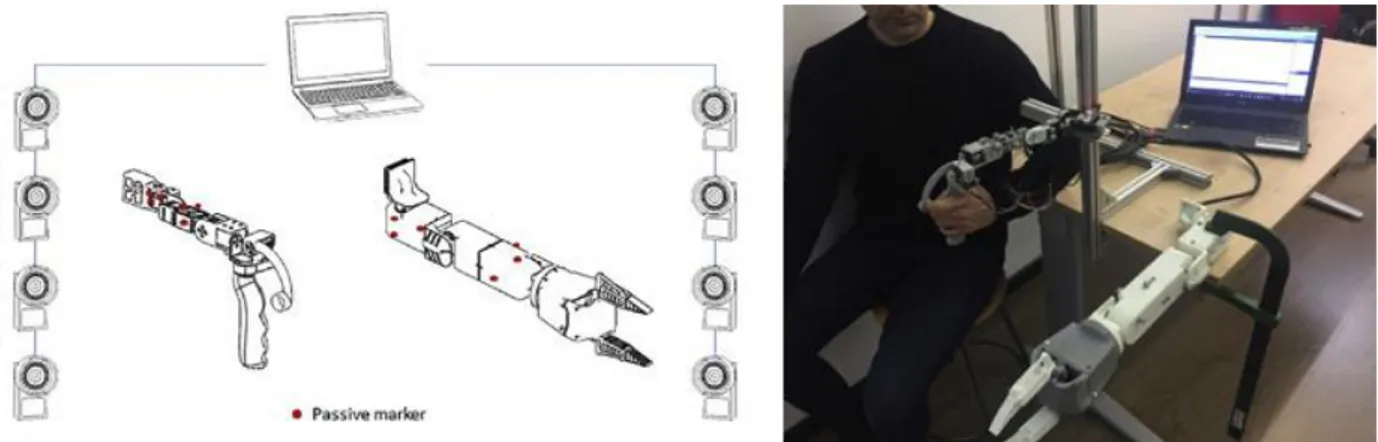
First, the position feedback has been addressed studying the kinematic performance of a hydraulic manipulator, in term of its accuracy and repeatability, used for underwater artifact cleaning activity. The manipulator has been re-designed during the CoMAS (In-situ conservation planning of Underwater Archaeological Artefacts) project. The results of the study have been of fundamental importance in the development of the control strategies for the control of the ROV and its manipulator. In fact, on the basis of the maximum error positions found and the kinematic performance of the arm it has been defined a “safety range” that allows avoiding collisions among the end-effector’s tool and the artifacts.
Second, the visual feedback has been addressed presenting an augmented reality visualization of scene depth for aiding ROV (Remotely Operated Vehicle) pilots in underwater manipulation. The architecture and the software of the system have been developed during the CoMAS project, while in this thesis has been provided the calibration of the whole system. In particular, combining the kinematics of the robotic arm and the standard photogrammetric model of the stereo camera, it has been possible to generate a depth map that shows to the pilots the distances of the surface of the scene objects from the end-effector's pose. Experimental trials have been carried out in the laboratory and in the water tank in order to evaluate and improve the performance of the system, approaching the target softly.
Despite the development of these feedbacks, currently, existing robotic manipulators are often too powerful and awkward to handle delicate or complex objects without damaging them. To figure this out, soft end effectors have been studied during my research internship at the faculty of Ocean Engineering of the University of Rhode Island (USA). The research activity has been carried out at the Robotics Laboratory for Complex
Robotics technologies. Specifically, the subject is divided into two main projects, studying both a universal jamming gripper and a hybrid toroidal soft gripper. The main purpose the universal jamming gripper has been to complete the integration with the existing arm, design and perform experiments with the gripper in the water tank, and propose refinements to the design of the mechanical and hydraulic system. While, the hybrid toroidal soft gripper has been designed, prototyped, and integrated with the existing arm and hydraulic system, to the end of carrying out a qualitative performance of the gripper in the water tank. The first extended trials of the hybrid toroidal soft gripper have been carried out at the Department of Mechanics, Energy, and Management (DIMEG) at the University of Calabria.
Il presente lavoro di tesi affronta in maniera organica diverse problematiche legate alle tecniche di manipolazione adoperate per la robotica subacquea e l’ingegneria marina. In particolare, si concentra sulle tecniche adottate per ridurre e migliorare il carico di lavoro a cui, spesso, piloti dei veicoli filoguidati, denominati ROVs (Remotely Operated Vehicles), biologi, oceanografi e ricercatori si trovano ad affrontare per raggiungere un obiettivo di manipolazione in ambiente subacqueo tramite bracci robotici.
A tal fine, il presente lavoro affronta le problematiche relative a tre linee di ricerca della manipolazione subacquea, riguardanti il feedback di posizionamento dell’end-effector del braccio robotico, l’arricchimento scena inquadrata con un feedback in realtà aumentata e infine di valutare la possibilità di manipolare oggetti fragili senza danneggiarli.
Le attività di ricerca riguardante i feedback di posizionamento e visivi si sono concretizzate studiando le tematiche emerse nell’ambito del progetto CoMAS (COnservazione programmata in situ di Manufatti Archeologici Sommersi). Nello specifico, durante il progetto è stato progettato un ROV, equipaggiato con un braccio robotico a 5 gradi di libertà, una stereo camera ottica e altri sensori acustici.
In primo luogo, la ricerca affronta il feedback di posizione studiando le prestazioni cinematiche di un manipolatore idraulico, utilizzato per l'attività di pulizia di manufatti archeologici subacquei. Nello specifico, sono state calcolate le performance del braccio robotico, in termini di accuratezza e ripetibilità, in maniera tale da definire un “safety range” che permette al pilota del ROV di approcciare l’end-effector al manufatto subacqueo in maniera delicata.
In secondo luogo, il feedback visivo è stato affrontato sviluppando una tecnica in realtà aumentata per la visualizzazione della mappa di profondità della scena inquadrata da una stereo camera in ambiente subacqueo in relazione alla posa dell'end-effector del braccio robotico. In particolare, combinando la cinematica diretta del braccio robotico e il modello geometrico fotogrammetrico della stereo camera, è stato possibile generare una mappa di profondità che mostra ai piloti ROV le distanze tra la superficie degli oggetti nella scena e la posizione dell'end-effector. Nella presente tesi si è affrontato il problema
In particolare, sono state condotte le attività di determinazione sperimentale del centro ottico della stereo camera e della posa relativa tra quest’ultima e la base del braccio, utilizzando differenti metodi presenti in letteratura. Infine sono stati condotti dei test di caratterizzazione del sistema sia in laboratorio che in vasca, in maniera da valutare l’avvicinamento controllato ai target.
Infine, soft grippers da montare come end-effector di bracci robotici trasportati da veicoli filoguidati sono stati studiati durante il periodo di ricerca all’estero, presso la facoltà di Ocean Engineering dell'Università del Rhode Island (USA). L’attività ha riguardato lo studio, l’ottimizzazione, la prototipazione e i test di grippers innovativi basati sull’approccio della Soft Robotics. Nello specifico, tali soft grippers sono capaci di modulare la rigidezza di materiale granulare contenuto all’interno di una membrana, in maniera tale da limitare passivamente la forza applicata a oggetti fragili, semplificandone la manipolazione. L’argomento è composto da due progetti principali, riguardanti lo studio e test del gripper “universale”, composto da una membrana, e il gripper “ibrido toroidale”, composto da due mambrane. Parte della fase sperimentale di caratterizzazione del gripper “ibrido toroidale” è stata successivamente condotta presso il Dipartimento di Ingegneria Meccanica, Energetica e Gestionale (DIMEG) dell’Università della Calabria.
First and foremost, I want to thank my supervisor Prof. Fabio Bruno. I appreciate all his contributions of time, idea, and positive attitude to make my Ph.D. experience productive and stimulating.
The members of the Industrial Design Group (Ing-Ind/15) have contributed immensely to my personal and professional time at the DIMEG. I am especially grateful to Professors Sergio Rizzuti, Maurizio Muzzupappa, and Luigi De Napoli, whose expertise, motivation and enthusiasm encouraged me through these years. My sincere thanks also go to my Research Group, all members of 3D Research, and Tech4Sea, a real source of friendships as well as good advice and collaborations.
I am also really grateful to R-CUE Lab of the University of Rhode Island (URI) for hosting me in a really edifying research period. In particular, I would like to express my gratitude to Prof. Stephen Licht, to giving me the opportunity to perform my internship within his research laboratory, and for his invaluable advice, patience, and eagerness to help me progress on my projects. An affectionate thought is for all guys in the lab and at the URI, who shared with me the work but, most of all, dinners and free time. I also thank Prof. Michelangelo La Luna and his family, that with their friendship and hospitality made me feel at home during my internship at the URI.
I thank all my friends and housemates for all the moments spent together and for both serious and trivial discussions about research, work, and life.
Lastly, I would like to thank my beloved family for all their love and encouragement. For the presence of my brothers Michele and Luciano, my sisters(-in-law) Antonella and Mariacarmela, and my lovely niece Serena. And most of all, I would like to thank my loving, encouraging, and patient girlfriend Elena, for supporting me day by day in this life’s journey.
I
Table of Contents
Table of Contents I
List of Figures III
Introduction 1
1. State of the art 5
1.1. Underwater robotics 5
1.1.1. Visual and positioning feedback solutions adopted to UVMSs 9
1.2. Underwater manipulations 19
1.3. Soft robotics 31
1.3.1. Soft robotic grippers 35
1.3.2. Underwater soft robotics 47
2. An underwater hydraulic arm for artifacts cleaning 57
2.1. Previous work 60
2.2. Kinematic performance evaluation 62
2.2.1. Experimentation 64
2.2.2. Results 77
3. Augmented Reality in underwater manipulation 81
3.1. Architecture 82
3.2. Software 85
3.3 Calibration of the system 87
3.3.1. Kinematic model of the arm 88
II
3.3.3. Camera to arm pose estimation 90
3.3.4. Determining the𝟎𝑻𝑪′ transformation matrix 93
3.3.5. Determining the 𝑪′𝑻𝑪 transformation matrix 94
3.4. Tests 103
3.4.1. Laboratory tests 103
3.4.2. Field tests 114
4. Soft Robotic jamming grippers 119
4.1. The University of Rhode Island 120
4.2. Universal jamming soft gripper 125
4.2.1. Previous Work 125
4.2.2. Integration of the gripper with Hydro-Lek arm 149 4.2.3. Underwater recovery of objects resting on the soft substrate 157
4.3. Hybrid toroidal soft gripper 165
4.3.1. Previous work 165
4.3.2. Design of the hybrid toroidal soft gripper 175
4.3.3. Trials in the water tank 188
4.4. Future development 203
Conclusions 204
Related publications 206
III
List of Figures
Figure 1. 1. Master controller prototype of the manipulators and the vehicle. Image taken from (Sagara &
Ambar, 2015). ... 9
Figure 1. 2. Potentiometers. Images taken from (Sagara & Ambar, 2015). ... 10
Figure 1. 3. Servo actuators. Images taken from (Sagara & Ambar, 2015). ... 10
Figure 1. 4. UVMS trials on the water tank. Images taken from (Sagara & Ambar, 2015). ... 11
Figure 1. 5. Desired (a) and actual (b) manipulator joint angles’. Images taken from (Sagara & Ambar, 2015). ... 12
Figure 1. 6. Master-slave controller. ROV. Images taken from (Sakagami, Shibata, & Inoue, 2010). ... 12
Figure 1. 7. Field trials. Images taken from (Sakagami, Shibata, & Inoue, 2010). ... 13
Figure 1. 8. Physical prototype of the arm. Image taken from (Barbieri et al., 2017)... 14
Figure 1. 9. Qualitative trials in the water tank. Image taken from (Barbieri et al., 2017). ... 14
Figure 1. 10. Characterization of the performance of the Master-Slave system. Image taken from (Barbieri et al., 2017). ... 15
Figure 1. 11. ORION manipulator. A nonlinear relationship between the piston excursion and the joint angle. Images taken from (Shim et al., 2010). ... 16
Figure 1. 12. Trial tasks. Images taken from (Shim et al., 2010). ... 16
Figure 1. 13. Some instant of the experimentation. Green lines represent virtual links between the current and desired position of the markers in the image. Image taken from (Marchand et al., 2001). ... 17
Figure 1. 14. An approach for Semi-Autonomous Recovery of Unknown Objects in Underwater Environments. (Prats et al., 2012). ... 18
Figure 1. 15. KAIKO vehicle. Courtesy of JAMSTEC, http://www.jamstec.go.jp/e/... 24
Figure 1. 16. Biological sediment collecting with KAIKO vehicle in the Mariana Trench. Courtesy of JAMSTEC. Images taken from ROV Planet journal, n° 2, pp 17-18. ... 25
Figure 1. 17. The ROV Jason. Image courtesy of Woods Hole Oceanographic Institution, http://www.whoi.edu/ ... 26
Figure 1. 18. Fluid and rocks lava sampling. Images courtesy of NOAA, https://oceanexplorer.noaa.gov/welcome.html ... 26
Figure 1. 19. The top and the tip of the chimney sampling. Images courtesy of NOAA. ... 27
Figure 1. 20. The ROV ISIS during the ERC CODEMAP2015 expedition. Courtesy of NOC, http://www.noc.ac.uk/ ... 28
Figure 1. 21. The ROV Victor 6000. Courtesy of Ifremer, http://flotte.ifremer.fr/fleet. Images taken from (Marchand et al., 2001). ... 28
IV
Figure 1. 22. Manipulation tasks with the ROV Victor 6000 and the Maestro manipulator during Seahma-1 cruise. a) Precise temperature measurements in a black smoker. b) Delicately shoveling of a hydrothermal crust deposited within the sediment. Images taken from (Jean-Louis et al., 2003). ... 29 Figure 1. 23. The ROV Hercules during recovery operations on board of the E/V Nautilus. Image courtesy of The
Ocean Exploration Trust, http://www.oceanexplorationtrust.org/ ... 29 Figure 1. 24. Underwater manipulation tasks of the ROV Hercules. a) Gas sampling. b,c,d) Sediment sampling.
Pictures courtesy of Nautilus Live, http://www.nautiluslive.org/ ... 30 Figure 1. 25. Structure of the electro-adhesion enabled soft gripper integrated with DEAs (a), and demonstration of gripping different objects (b, c, d, e, f). Image taken from (Shintake et al., 2016). ... 32 Figure 1. 26. Octopus-inspired robot. (A) Octopus vulgaris grasping a human finger. (B) An octopus-like robot
arm wrapping around a human wrist in the water. (C) Detail of the design. (D) Detail of the SMA spring. Image taken from (Kim et al., 2013). ... 33 Figure 1. 27. A multigait soft walker powered by compressed air. Image taken from (Shepherd et al., 2011). .... 34 Figure 1. 28. Gripping by actuation. a) Contact-driven deformation. b) Tendon-driven. c) Fluidic elastomer
actuators (FEAs). Courtesy of (Rus and Tolley, 2015). d) Dielectric elastomer actuators (DEAs). e) Ionic polymer-metal composites (IPMCs). Courtesy of (Sun et al., 2013). f) Shape memory alloys (SMAs). Courtesy of (Wang et al., 2016). g) Shape memory polymers (SMPs). Courtesy of (Behl et al., 2007). Image taken from (Shintake et al., 2018)... 36 Figure 1. 29. Soft grippers using passive structure with external motors. a) Fin Ray robotic gripper. Courtesy of
Festo Co. Ltd. b) Fin Ray (toy). Courtesy of BionicToys HmbH. c) Working principle of compliant mechanism (Petkovic et al., 2013). d) Compliant mechanism (Liu et al., 2017). e) Tendon-driven with elastic hinges (Ma et al., 2017). f) Anthropomorphic tendon-driven (Xu and Todorov, 2016). g) Tendon-driven with sensor embedded soft skin (Tavakoli et al., 2017). h) Tendon-driven elastomeric manipulator (Calisti et al., 2011). i) Tendon-driven with a compliant elastomeric bag (Zhu et al., 2016). Images taken from (Shintake et al., 2018). ... 37 Figure 1. 30. Soft grippers using fluidic elastomer actuators (FEAs). a) Suzumori’s multichambered fingers. b)
PneuNets (Ilievski et al., 2011). c) Fingers actuated by electrohydrodynamics (Yamaguchi et al., 2011). d) Bio-inspired hand (Deimel and Brock, 2016). e) Pouch motors. f) Hydraulically actuated hydrogels (Yuk et al., 2018). g) Self-healing polymers (Terryn et al., 2018). h) Chameleon’s tongue inspired bladder. Courtesy of Festo Co. Ltd. i) Microtentacle (Paek et al., 2015). Images taken from (Shintake et al., 2018). ... 39 Figure 1. 31. Soft grippers using dielectric elastomer actuators (DEAs) and ionic-polymer-metal composites
(IPMCs). a) Dielectric elastomer minimum energy structure (DEMES) (Kofod et al., 2007). b) Segmented DEMES (Lau et al., 2017). c) DEA with stiff fibers (Shian et al., 2015). d) IPMC fingers (Bar-Cohen et al., 1998). e) Micro-IPMC fingers (Deole et al., 2008). Images taken from (Shintake et al., 2018). ... 40
V
Figure 1. 32. Soft grippers using actuation of shape memory materials. a) Bidirectional shape memory polymers (SMPs) (Behl et al., 2013). b) 3D printed SMP structure (Ge et al., 2016). c) Shape memory alloys (SMAs) with elastomeric fingers structure (She et al., 2016). d) Articulated elastomeric structure with SMA wires
(Kim et al., 2016). e) SMA microfingers (Lan et al., 2011). Images taken from (Shintake et al., 2018). ... 42
Figure 1. 33. Soft gripper using particle jamming. a) Representative configuration, its working mechanism. b) Holding force for different types of object geometry. Image taken from (Brown et al., 2010). ... 43
Figure 1. 34. Soft grippers using particle jamming. a) Two-fingered configuration (Amend and Lipson, 2017). b) Combination with fluidic elastomer actuator (Yang et al., 2018). Images taken from (Shintake et al., 2018). ... 44
Figure 1. 35. Soft grippers using electro-adhesion. a) Flexible-PCB with external magnetic motors. Courtesy of Grabit Inc. b) Flexible-PCB with external magnetic motors (Schaler et al., 2017). c) Combination with fluidic elastomer actuators (FEAs) (Liang et al., 2017). d) Integration with dielectric elastomer actuators (DEAs). Images taken from (Shintake et al., 2017, 2018). ... 45
Figure 1. 36. Soft grippers using gecko-adhesion. a) Combination with a passive mechanism that pre-loads microfibers arranged on a flexible film substrate (Hawkes et al., 2015; Suresh et al., 2015). b) Combination with fluidic elastomer actuators (FEAs) (an inflatable membrane) (Song and Sitti, 2014). c) Holding of different items by an elastomer membrane with mushroom-shaped microfibers (Song et al., 2017). Images taken from (Shintake et al., 2017, 2018). ... 46
Figure 1. 37. Underwater soft grippers developed during the years. ... 47
Figure 1. 38. OceanOne while helping diver operations. Credit: Stanford University. ... 48
Figure 1. 39. Bellows-type soft gripper. Image taken from (Galloway et al., 2016). ... 49
Figure 1. 40. Boa-type soft gripper. Image taken from (Galloway et al., 2016). ... 49
Figure 1. 41. Two finger gripper with bellows-type actuators grasping a delicate sea cucumber. Credit: Wyss Institute at Harvard University. ... 50
Figure 1. 42. Tree finger gripper with bellows-type actuators grasping a sea anemone. Credit: Wyss Institute at Harvard University. ... 51
Figure 1. 43. Fully 3D-printed version of the gripper. Credit: Wyss Institute at Harvard University. ... 52
Figure 1. 44. Trials in the deep water. Image taken from ROV Planet Journal, n.14 pp. 32. ... 52
Figure 1. 45. Overview of the deep-sea soft robotic arm system. (A) Control of actuators is achieved using a sensorized wireless glove, which coordinates the control of independent proportional valves that distribute pressure to the arm and end-effector actuators. (B) A custom open-circuit seawater engine regulates hydraulic pressure to independent ports, and can operate at depths of at least 2500m. (C) The soft arm, consisting of bending, rotary, and gripping modules, can be mounted independently or as part of an existing manipulator system. Image taken from (Phillips et al., 2018). ... 53
VI
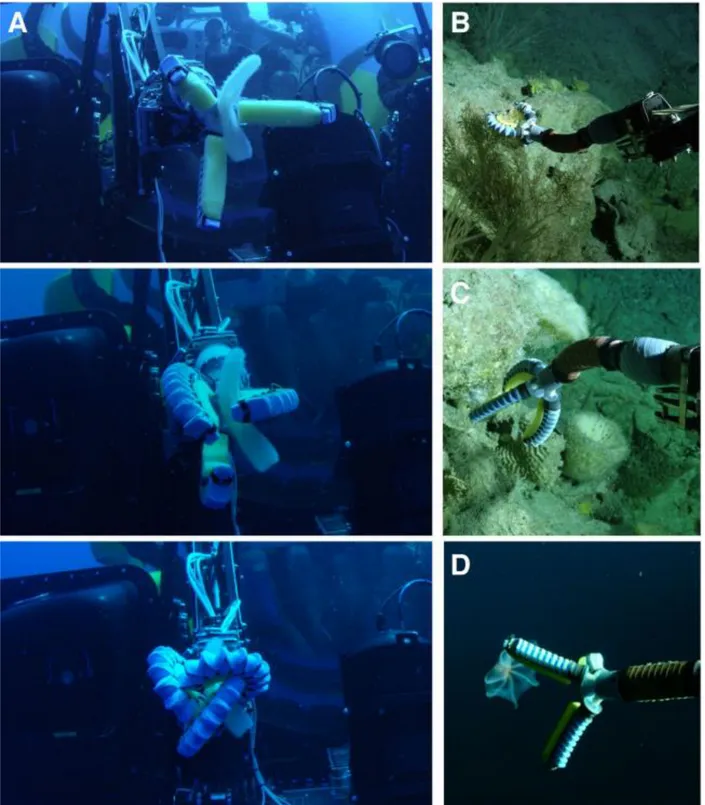
Figure 1. 46. Field testing using a Triton 3K3 manned submersible vehicle. (A) Image sequence of the soft manipulator grasping a midwater pyrosome (Pyrosoma atlanticum) in the water column, as observed from a diver. (B) The soft manipulator articulating upwards to grasp a coral at approximately 300m depth and (C) downwards to grasp a sponge. (D) Manipulator straightened out to approach the deep-sea octopus.
Image taken from (Phillips et al., 2018). ... 54
Figure 1. 47. The rotary actuated dodecahedron sampler, invented by researchers at URI and Harvard, has five origami-inspired “petals” arranged around a central point that fold up to safely capture marine organisms. Credit: Wyss Institute at Harvard University. ... 55
Figure 1. 48. Underwater soft jamming gripper holding force test in deep sea. Image taken from (Licht et al., 2017). ... 56
Figure 2. 1. The rendering of the electromechanical brush mounted on the redesigned Pan & Tilt assembly. ... 60
Figure 2. 2. Modified arm and electric brush mounted on the ROV’s skid. ... 61
Figure 2. 3. Method for evaluating the kinematic performances of the robotic arm. ... 62
Figure 2. 4. Zero-reference configuration of the robotic arm and DH notation. ... 65
Figure 2. 5. Schematic representation of the underwater manipulator with D-H convention and parameters. ... 65
Figure 2. 6. Schematic representation of the quadrilateral mechanism and characteristic parameters. ... 67
Figure 2. 7. Local reference frame and geometric parameters of the end-effector tool. ... 67
Figure 2. 8. Homing procedure: encoder value to joint angle. The encoder of the 4th joint is configured in multi turn mode... 68
Figure 2. 9. Data acquisition software of the arm’s sensors. The absolute encoders are pointed out with the name Enc 23, 25, 27, SSI 1 and 2. ... 69
Figure 2. 10. Scanning setup for acquiring actual end-effector poses. ... 73
Figure 2. 11. Coordinate system {B} adopted in the scanning activities. ... 74
Figure 2. 12. 3D point cloud and reference system {Opt} of the laser scanner optical center. ... 75
Figure 3. 1. The ROV equipped with the custom-made robotic arm and optical-stereo camera. ... 82
Figure 3. 2. The re-engineered underwater arm mounted on the skid of the ROV. ... 83
Figure 3. 3. Optical-stereo camera. ... 84
Figure 3. 4. Control software for the AR scene depth visualization. ... 86
Figure 3. 5. Mathematical model representation of the proposed system. ... 87
Figure 3. 6. Geometrical model of the stereo camera. ... 90
Figure 3. 7. Geometric approach to determine 𝟎𝑻𝒄 matrix. ... 91
Figure 3. 8. Geometric approach to determine 𝒄′𝑻𝒄 matrix. ... 92
VII
Figure 3. 10. Acquisition phase and single reconstruction result obtained with the NextEngine 3D laser scanner. ... 94 Figure 3. 11. Results of the calibration process. (a) Pose estimation of the calibration sample with respect to the
reference frame of the optical-stereo camera {C}. (b) Interior and exterior orientation parameters of the stereo rig. ... 95 Figure 3. 12. Schematic layout of the set-up used to calculate the rigid transformation matrix 𝑪′𝑻𝑪 . ... 96 Figure 3. 13. (a) Optical-stereo camera mounted on tripod with reflective markers, (b) and experimental set-up.
... 97 Figure 3. 14. Distance between the planes π1 and π2. For ease of understanding is visible only the left camera.
... 100 Figure 3. 15. a) Re-projection of the corners of the chessboard on the plane image of the left camera. They were
considered 6 x 7 corners of the chessboard. b) Coordinates of the corners of the chessboard with respect to the optical center of the stereo camera. ... 101 Figure 3. 16. The CAD representation of the roto-translation matrix between the reference systems {C} to {0}.102 Figure 3. 17. Experimental set-up. ... 104 Figure 3. 18. Results of the optical-stereo camera measurement accuracy. (a) Trend of RMSE values for different
distances between the optical-stereo camera and the objects in the workspace. (b) Statistics for accuracy estimation of the optical-stereo camera (mm). ... 106 Figure 3. 19. (a) Reference 3D model overlaid on the gathered point cloud. (b) Gathered point cloud colored
according to the distance between each point and the reference 3D model. ... 107 Figure 3. 20. Error histogram of the Euclidian distance (mm) between the point cloud and the reference 3D
model representing the acquired amphora. ... 107 Figure 3. 21. Three different poses of the robotic arm within its working volume to perform the accuracy
estimation. ... 109 Figure 3. 22. The point clouds generated by the laser scanner visualized in JRC Reconstructor. Pose 1. Distance
object 1.5 m. ... 110 Figure 3. 23. The point clouds generated by the optical-stereo camera visualized in MeshLab. Pose 1. Distance
object 1.5 m. ... 110 Figure 3. 24. The point clouds generated by the laser scanner and by the optical stereo-camera. Pose 2. Distance object 1.5 m. ... 111 Figure 3. 25. (a) Comparison of the trend of RMSE values for three poses of the robotic arm when varying the
distance between the optical-stereo camera and the objects in the workspace. (b) Statistics for accuracy estimation of the overall system (mm). ... 111 Figure 3. 26. The point clouds generated by the laser scanner visualized in JRC Reconstructor for a generic static
VIII
Figure 3. 27. The point clouds generated by the optical-stereo camera visualized in MeshLab. ... 113
Figure 3. 28. Depth map augmented on the visual feedback. ... 114
Figure 3. 29. Field tests preparation in a large pool at the WASS SpA. The umbilical of the ROV is connected to the TMS (Tether Management System). ... 115
Figure 3. 30. The end-effector's brush approaches the target. ... 115
Figure 3. 31. User interface with different display windows. ... 116
Figure 3. 32. RGB scalar field window of the camera control software. ... 117
Figure 4. 1. Rhode Island. ... 120
Figure 4. 2. URI tagline. ... 121
Figure 4. 3. URI Kingston Main Campus. ... 121
Figure 4. 4. URI Bay Narragansett Bay Campus. ... 122
Figure 4. 5. GSO. R/V Endeavor. ... 123
Figure 4. 6. Ocean Engineering research and teaching program. ... 123
Figure 4. 7. Jamming gripper mechanism described in Brown et al (2010). ... 126
Figure 4. 8. First jamming gripper schematic and prototype. Source: Pr. Licht. ... 127
Figure 4. 9. Compliant jamming gripper mounted on the VideoRay 3. Source: Pr. Licht. ... 128
Figure 4. 10. Trials in the water tank. Collecting of objects resting on hard surface. Source: Pr. Licht. ... 129
Figure 4. 11. An under-filled jamming gripper with floating cap mounted on the 5-DOF arm of SeaEye Falcon ROV, recovering a small object in a 5m water tank. Source: Pr. Licht. ... 130
Figure 4. 12. The arrangement of the bead chains mounted on the prototype of the gripper. Source: Pr. Licht. 131 Figure 4. 13. Annotated schematic of gripper apparatus and fluid drive system. Ref: Licht et al. (2017). ... 132
Figure 4. 14. Annotated schematic of bench top gripper experiments in a pressurized water chamber. Ref: Licht et al. (2017). ... 134
Figure 4. 15. Schematic illustrating motion of gripper and platen during benchtop experiments. Ref: Licht et al. (2017). ... 136
Figure 4. 16. Gripper lifting force, FL, is shown at six jamming pressures, PJ, where ambient pressure PA = 4 atm, gripper weight FW = 5 N, and initial fluid volume VI = 120 mL. Ref: Licht et al. (2017). ... 137
Figure 4. 17. Gripper lifting force, FL, in function of initial fluid volumes VI. Ref: Licht et al. (2017). ... 138
Figure 4. 18. Comparison of the membrane shape during grasp with VI = 40 and VI = 120 mL. (a) Just before contact. (b) Before jamming. (c) After jamming. (d) Max pull force. Ref: Licht et al. (2017). ... 139
Figure 4. 19. a) Experimental apparatus. b) Schematic illustrating motion of gripper and platen during benchtop experiments. Ref: Licht et al. (2018). ... 139
IX
Figure 4. 20. Image sequences (left to right) from trials with the membrane 25% (top), 50% (middle), and 100% (bottom) full of jamming particles, and initial volume fractions (air + particles) Vi = 0.47, 0.72, and 1.22,
respectively. Ref: Licht et al. (2018). ... 141
Figure 4. 21. Experimental results for all target configurations. For clarity, the rod results and the cylinder/disc results are shown separately; scaling is maintained to allow direct comparison. Ref: Licht et al. (2018). . 142
Figure 4. 22. Lift and support forces are compared for all trials with the three solid samples. Ref: Licht et al. (2018). ... 143
Figure 4. 23. (left) ROV Hercules stored on deck prior to dive. (upper-right) Image of the gripper held by the manipulator, captured from the main camera view used by the ROV pilot. (bottom-right) Image capture from operator video taken during testing of gripper on four objects resting on the ‘front porch’ of the ROV at a water depth of 1200m. Ref: Licht et al. (2017). ... 145
Figure 4. 24. Estimation of maximum lift forces were derived from video frames captures showing compression of the lower spring. Ref: Licht et al. (2017). ... 147
Figure 4. 25. Jammed gripper shapes immediately after pulling free from the sample rod during tests at depth on the ROV Hercules. The formation of the tabs indicates that interlock was achieved. Ref: Licht et al. (2017). ... 148
Figure 4. 26. Hydro-Lek HLK-43000 with the rope cutter tool mounted on the skid of the Saab SeaEye Falcon DR ROV. ... 150
Figure 4. 27. Cross-section of the wrist of the arm. ... 151
Figure 4. 28. First CAD model of the proposed solution. ... 152
Figure 4. 29. The CAD model of the Pan & Tilt mechanism mounted on the wrist of the arm. ... 153
Figure 4. 30. Tilt movement due to the piston excursion. ... 154
Figure 4. 31. The gripper was mounted on a Hydro-Lek 5-function arm, with the wrist degree of freedom actuated as shown. ... 154
Figure 4. 32. The assembly phase of 3D printed and commercial components of the pan & tilt mechanism. ... 155
Figure 4. 33. Assembled soft gripper mounted on the Hydro-Lek arm, pictured while grasping objects (screw driver). ... 156
Figure 4. 34. Objects used in demonstration. (a) weighted hair brush (b) lightbulb (c) metal spring (d) lightbulb (e) wine glass (f) wine glass (g) shell (h) weighted GoPro housing (i) shell (j) plastic safety glasses (k) clam shell. ... 157
Figure 4. 35. Preparation of the wave tank for the trials at the URI. ... 158
Figure 4. 36. Experimental set-up in the water tank. ... 159
Figure 4. 37. VideoRay operator point of view. Homemade base with memory foam and the sandbox. Meanwhile, the gripper is picking up a big shell. ... 160
X
Figure 4. 38. Procedural protocol to carry out the trials. a) Approach the object with the balloon in jammed state; b) Fill the balloon before contact (2-5 cm above the object); c) Cover the object under the weight of
the gripper; d) Jam the particle inside the balloon; e) Lift the object; f) Release the object on the foam. . 161
Figure 4. 39. Representative images demonstrating robotic operation of partially filled gripper on various objects resting on soft sediment and foam. The failure mode for the only unsuccessful grasp is shown in the bottom right figure. ... 162
Figure 4. 40. Images demonstrating typical failure mode when attempting to grasp object on soft sediment with a fully filled gripper. Successful grasp was only achieved on object d, as shown in the lower three frames. ... 163
Figure 4. 41. The CAD models of the Hybrid gripper developed for Saab ROV/Hydro-Lek arm (a) and for Hercules ROV/Predator arm (b). Source: Pr. Licht. ... 165
Figure 4. 42. Air trials. a) ABS plastic wavy cylinder. b) Pretzel rods. Source: Pr. Licht. ... 166
Figure 4. 43. Multi-Channel Low-pressure drive. Source: Pr. Licht... 167
Figure 4. 44. Design and prototype of the gripper. Source: Pr. Licht. ... 167
Figure 4. 45. Trials at 200 meters’ deep coral reef. Source: Pr. Licht. ... 168
Figure 4. 46. Deep sea trials in exciting conditions off the coast of Rhode Island, and visibility of approximately one meter. Source: Pr. Licht. ... 168
Figure 4. 47. a) Hybrid gripper pad. b) Integration with Predator Arm. Source: Pr. Licht. ... 170
Figure 4. 48. Prototyping and qualitative testing of the gripper. Source: Pr. Licht. ... 171
Figure 4. 49. USS Independence CVL-22 with the aircraft on deck. ... 172
Figure 4. 50. Lights of the ROV Hercules illuminate the bow of the USS Independence. ... 174
Figure 4. 51. Grumman Hellcat fighter aircraft seen in aircraft elevator hatch. Anti-aircraft weaponry surrounded by massive glass sponges. ... 174
Figure 4. 52. Functional requirements. ... 176
Figure 4. 53. CAD model of the Concept 1. ... 177
Figure 4. 54. The opening/closing mechanism of the fingers. ... 178
Figure 4. 55. Components of the soft end-effector... 179
Figure 4. 56. Static FEM analysis of the two fingers. ... 180
Figure 4. 57. A rolling diaphragm cylinder. Image taken from (Whitney et al., 2014). ... 181
Figure 4. 58. New configuration of the gripper. ... 182
Figure 4. 59. The gripper in the closing mechanism configuration. ... 183
Figure 4. 60. Assembled soft robotic gripper mounted on the Hydro-Lek arm. ... 184
Figure 4. 61. CAD model of the jamming gripper. ... 185
XI
Figure 4. 63. a) Approaching the object. b) The manifolds slide into linear bearings while the membranes are
surrounding the object. c) “Jamming effect”. ... 188
Figure 4. 64. Objects used in the trials. ... 190
Figure 4. 65. The experimental set-up of the trials carried out at DIMEG. ... 193
Figure 4. 66. Manual tests on object 6. a) Positioning. b) Approaching. c) Holding. ... 193
Figure 4. 67. Membrane condition variation shown during grasping of the object 7. a) partially filled 50%. b) nearly full 90% (grasp failed). c) Jammed. ... 194
Figure 4. 68. Representative images demonstrating manual test of the gripper on selected objects. ... 196
Figure 4. 69. Manipulation test of the object 6. a) Approaching the object with the arm, balloons 50% filled. b) Jamming the balloons. c) Manipulation. d) Release of the object on a tray. ... 198
Figure 4. 70. Manipulation of the object 14. a) Manipulation. b) Sliding of the Mini Might and shafts to prevent overpressure on the object. c) Detail of the jamming balloons during manipulation. d) Detail of the balloons after release of the object. ... 199
Figure 4. 71. Torque tests. Manipulation of the object 15 (a, b), 16 (c) and 17 (d). ... 200
Figure 4. 72. Manipulation of the amphora. a) All extended arm. b) Approaching the amphora. c) Closing the pincer – balloons 50% filled. d) Jamming and grasping. e) Manipulating. f) Releasing on a tray. ... 201
1
Introduction
Underwater manipulation has been widely investigated during the last few years. In fact, it is a key technology for marine industries and exploration that can be efficiently adopted in other application fields, such as underwater archaeology, biological manipulation, scientific expedition, as well as offshore construction in the Oil and Gas industry.
All these operations require a high quality of the work and a precise positioning of the manipulator’s end-effectors, that makes intervention capacity of the ROV/AUV very challenging while working with manipulators under water. To this end, the aim of the scientific community in the field of underwater robotics is to develop a force-position feedback manipulator able to protect sensitive equipment on the seabed, as well as the environment. Nevertheless, the physical properties of an underwater manipulator may differ from the corresponding ideal values due to geometric errors, such as manufacturing tolerances and assembly misalignments, and non-geometric errors, such as the elastic deflection of the links, thermal deformations, and vibrations. Then, in many cases, manipulators do not behave according to their design but they make mistakes in achieving a specific pose or following trajectories. An error compensation process, that allows to identify and compensate these errors in the mathematical model of the robotic arm, needs to be carried out in order to overcome these limitations and improve the accuracy of the end-effector.
Additionally, underwater manipulation is performed remotely by expert pilots thanks to the visual feedback provided by one or more cameras but without any information about the distance between the end-effector and the target. To this end, different solutions have been presented in the literature improving the visual feedback in the operated underwater manipulation, by reducing the burden on the human operator.
Despite the development of these feedbacks, currently, existing robotic manipulators are often too powerful and awkward to handle delicate or complex objects without damaging them. Soft and compliant grippers have been shown to dramatically simplify the problem of grasping complex objects with robotic manipulators. They can be designed to passively
2
limit the force that is applied to fragile or sensitive objects, even when the exact shape of the object is unknown prior to grasping. For these reasons, (ease of grasping, force limiting without sensors, and inherent robustness) soft robotic grippers are an excellent match for the challenging problems that confront marine archaeologists and marine biologists sampling in the deep ocean.
To this end, this thesis addresses the challenging problem of three different area of underwater manipulation:
position feedback; visual feedback;
manipulation of fragile objects.
In particular, the position feedback has been addressed studying the kinematic performance of a hydraulic manipulator, used for underwater artifact cleaning activity. The manipulator has been re-designed during the CoMAS project. Firstly, the forward kinematic model of the robotic arm has been defined according to D-H notation. Subsequently, a data acquisition phase is carried out by collecting the joint angle values that are known by reading the absolute encoders mounted on the robotic arm. The forward kinematic model and the joint angle values collected are integrated in order to obtain a set of predicted end-effector poses. An external metrology system has been adopted in order to measure the actual end-effector pose in some different configurations. Next, the measurements of the predicted and the actual poses are compared in order to have an estimation of the positioning errors that are necessary for the definition of the kinematic performance of the robotic arm. And finally, the kinematic performance of the robotic arm, consisting in the repeatability and accuracy, are calculated according to the ISO standard 9283:1998.
The visual feedback has been addressed presenting an augmented reality visualization of scene depth for aiding ROV pilots in underwater manipulation. The architecture and the software of the system have been developed during the CoMAS project, while in this thesis has been provided the calibration of the whole system.
In particular, combining the kinematics of the robotic arm and the standard photogrammetric model of the stereo camera, it has been possible to generate a depth
3
map that shows to the pilots the distances of the surface of the scene objects from the end-effector's pose. Experimental trials have been carried out in the laboratory and in the water tank in order to evaluate and improve the performance of the system.
Finally, soft end effectors have been studied during my research internship at the faculty of Ocean Engineering of the University of Rhode Island (USA). The research took place at the Robotics Laboratory for Complex Underwater Environments (R-CUE) under the supervision of Prof. Stephen Licht. In particular, the research focuses on continues the development, prototyping, and testing of the compliant jamming grippers developed at the R-CUE. Specifically, the subject is divided into two main projects, studying both a universal jamming gripper and a hybrid toroidal soft gripper. The main purpose the universal jamming gripper has been to complete the integration with the existing arm, design and perform experiments with the gripper in the water tank, and propose refinements to the design of the mechanical and hydraulic system. While, the hybrid toroidal soft gripper has been designed, prototyped, and integrated with the existing arm and hydraulic system, to the end of carrying out a qualitative performance of the gripper in the water tank. The first extended trials of the hybrid toroidal soft gripper have been carried out at the Department of Mechanics, Energy, and Management (DIMEG) at the University of Calabria.
Thesis started with an overview of thesis main topics and objectives, presented in this Introduction Chapter. The work encompasses different topics (underwater robotics, underwater manipulation, soft robotics, and underwater soft robotics and grippers). Chapter 1 tries to give an extensive background of all problems tackled in the thesis, of chosen approaches and relevant possible alternatives.
Then, Chapter 2 treats a study conducted for evaluating the kinematic performance of a hydraulic underwater manipulator for artifacts cleaning.
Chapter 3 discusses a novel system based on a sensorized robotic arm, stereoscopic 3D perception and augmented reality visualization to support ROV's pilots in underwater manipulation tasks.
In Chapter 4, focused on the development, prototyping, and testing of compliant jamming grippers, for the challenging problems that confront marine archaeologists and marine
4
biologists sampling in the deep ocean, developed during my internship at the University of Rhode Island (USA).
Finally, a Conclusion Chapter summarizes topics and results and considers possible further developments and research lines.
5
1. State of the art
In this section, a review of commonly employed underwater robotics is presented, in line with the purpose of the thesis. First, a brief introduction showing the constantly expanding role of marine robotics in ocean engineering is given, considering some historical backgrounds given by projects that have succeeded over the years. Next, the effort will be focused on research aspects of underwater robotics, regarding manipulators, vehicles and control systems, that together are defined as Underwater Vehicle Manipulator System (UVMS). In particular, have been analyzed different solutions implemented in literature with the end of improving the visual and positioning feedback, as well as guidance and control algorithms of the UVMS.
Next, we will focus on relievable scientific aspects of underwater manipulations, related to the use of robotic arms mounted on underwater vehicles to accomplish specific biological/scientific tasks.
Finally, the proliferation of soft robotics research worldwide has brought substantial achievements in terms of principles, models, technologies, techniques and prototype of soft robots. After a review, we will focus on relievable technologies and applications that can be actually adopted to ensure a soft touch in the underwater field.
1.1. Underwater robotics
Water covers more than 70% of our planet and, owning to hostile condition of deep seas, only a little percentage of seafloor is known and explored. The remaining part represents a potential huge source of information for biologists, geologists, archaeologists and many other researchers. The first scientific explorations were conducted primarily through the use of diving and human-occupied submersibles. Nowadays, technology progress provides tools and methodologies to investigate this unknown world. Underwater vehicles can represent a powerful tool for every kind of underwater activities. In many
6
circumstances, their employment is indispensable because of hostile time and condition operation. Scuba diver operations are, indeed limited up to fifty meters. Moreover, the operation time is inversely proportional to the depth. Even if they can noticeably differ from each other in size, costs, and capabilities, a general classification divides underwater vehicles in manned and unmanned (UUVs); the latter can be differentiated in Remotely Operated Vehicles (ROVs) and Autonomous Underwater Vehicles (AUVs). Manned submersible can dive up to known depths, directly driven by an operator, and sometime, hosting more than one human per mission. They can recover artifacts, manipulate the environment having scientist in-situ. Big disadvantages are the extremely high costs, both of vehicle and of deployment operation, and the limited underwater time.
Underwater Unmanned Vehicles (UUVs) can perform surveys in areas inaccessible to humans, and deploy a wide range of sensors useful for acquiring relevant data. At the present day, ROVs are probably the most used platforms, able to operate with guidance from outside while doing a survey. There is a link between the surface and the underwater vehicle made up by a so-called umbilical cable, which is used for the vehicle control, energy supply and data exchange. They are characterized by having their own means of propulsion. Generally, ROVs can perform different operations uninterruptedly and are able to recover artefacts. Apart from operator fatigue, their main constraints are due to the umbilical that limits depths, range and mobility; moreover, for large depths the umbilical winch increases and consequently the size of the ship that can support it. AUVs have a high degree of autonomy in the sense that they can navigate and locate itself using only their on-board sensors, and without permanent communication. AUVs have unmanned and untethered design, which makes them well suited to extended exploratory surveys requiring minimal user intervention and support. Meanwhile, their autonomous free-swimming capability has added a new paradigm of ocean sampling to the scientific user community as demonstrated. They complement the capabilities of tethered remotely operated vehicles (ROVs). They have relatively low operational costs, also because of fast surveying capabilities. Main drawbacks are the limited battery autonomy and the self-position estimation inside surveyed scene that can drift in large areas. Moreover, capability of recovering and interventions are nowadays limited and object of studies. Furthermore, researcher and scientists are increasingly interested in the use of
7
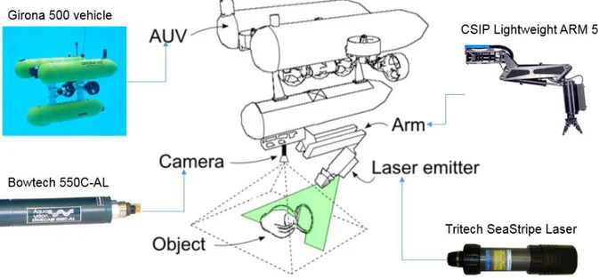
unmanned surface vehicles (USVs) for a variety of missions and applications. The term USV refers to any vehicle that operates on the surface of the water without a crew. Several research projects have succeeded over the years, showing interest in underwater robotics. In the TRIDENT project, different mechatronic systems were integrated into the Girona-500 AUV to operate autonomously in specific underwater manipulation tasks (Ribas, et al., 2015). One of the most interesting projects has been carried out by the University of Hawaii, which has produced an AUV capable of carrying out manipulation tasks autonomously (Marani & Yuh, 2009). The project, which gives the vehicle's name, is called SAUVIM (Semi-Autonomous Underwater Vehicle for Intervention Mission). The vehicle is equipped with a manipulator with 7 DOF that, thanks to a force and torsion sensors positioned upstream of the wrist, and a camera tracking system is able to follow the position of the end-effector with a feedback, to carry out various autonomous operations.
Also worthy of note is the study carried out within the project AMADEUS (Advanced MAnupilator for DEep Underwater Sampling). AMADEUS is a dexterous subsea robot hand incorporating force and slip contact sensing, using fluid-filled tentacles for fingers (Lane, et al., 1998). In addition to the mechanical design, development of the hand has also considered closed loop finger position and force control, coordinated finger motion for grasping, force and slip sensor development/signal processing, and reactive world modeling/planning for supervisory ‘blind grasping’. Furthermore, the project focused on the realization of a set-up composed of two 7-DOF ANSALDO manipulators to be used in cooperative mode (Casalino, et al., 2001).
ALIVE is a 4 DOF intervention AUV with a 7 DOF manipulator which is capable of autonomous navigation towards a position nearby an underwater intervention panel, detection of the panel and, finally, approaching and docking to the panel with two hydraulic grabs. Other projects are reported in Table 1.1. Each project involves different instrumentations and obviously a vehicle equipped with one or two manipulators (Table 1.1).
8
Project Vehicle Manipulator
ALIVE ALIVE 7-DOF
manipulator
VENUS KAIKO
JAMSTEC 7 DOF manipulator TRIDENT GIRONA-500 CSIP
Light-weight ARM 5E
SAUVIM SAUVIM
ANSALDO MARIS 7080
7-DOF
AMADEUS Heriot - Watt ANGUS 002 ANSALDO MARIS 7080 7-DOF NEPTUNE ROPOS 2 x Shilling Robotics TITAN 4
Table 1.1. Underwater projects succeeded over the years.
The effort developed in these projects make marine a challenging engineering problem with strong connections to several engineering domains. In fact, a major challenge concerning underwater robotics is the interaction with the environment by means of one or more manipulators. Autonomous UVMSs are still the object of research; the current trend is in developing the first semiautonomous robotic devices, which might be acoustically operated; moreover, if physically possible, the capability to dock to the structure where the intervention is needed might significatively simplify the control. The final aim might be to develop a completely autonomous UVMS, able to localize the intervention site, recognize the task to be performed, and act on it without docking to the station and without human intervention. This might make it possible to perform missions that are currently impossible such as autonomous archaeological intervention at deep sites.
9
1.1.1.
Visual and positioning feedback solutions
adopted to UVMSs
Here the attention will focus on different solutions implemented in literature, to the end of improving the visual and positioning feedback, as well as guidance and control algorithms of the UVMS.
In the research work performed by (Sagara & Ambar, 2015) are addressed the control problems of an underwater robot equipped with two electrical 3-DOF (degree of freedom) manipulators. The innovation introduced into the state of the art is the development and prototype of a simple and intuitive master-controller, capable of moving the vehicle and the two arms simultaneously (Figure 1. 1).
Figure 1. 1. Master controller prototype of the manipulators and the vehicle. Image taken from (Sagara & Ambar, 2015).
The robot base main master controller enables the user to control the motion of a slave robot in 3-dimensional space (3-DOF position and 3-DOF attitude) using only one hand. First, the translational motion of a robot (x, y, and z-axes) can be controlled using three slide-type potentiometers installed in a box-shaped controller. The translational speed of the robot is proportional to the changes of electrical potential (voltage) from the
10
potentiometers. Thus, the translational speed of the robot base can be controlled by adjusting the slide potentiometer levers (Figure 1. 2).
Figure 1. 2. Potentiometers. Images taken from (Sagara & Ambar, 2015).
The robot base controller consists of three servo actuators, with which is possible to control the Euler angles (Roll, Pitch, and Yaw) of the slave vehicle (Figure 1. 3).
11
Each joint is actuated by an RS302CD servo actuator (Futaba Corporation) using an RS-485 communication protocol. These servo actuators are used to provide the desired joint angles for the manipulators of the slave robot including keeping any desired postures of the slave robot manipulators. Each end-tip of the manipulator master controller is attached with a vehicle sub-master controller that consists of a joystick and tactile switches (SparkFun Electronics). The experiment was carried out in a water tank. The position and attitude of the robot can be calculated by monitoring the movement of three LEDs’ light sources via CCD cameras. The data from CCD cameras were converted to position data using an X–Y video tracker (Figure 1. 4).
Figure 1. 4. UVMS trials on the water tank. Images taken from (Sagara & Ambar, 2015).
The research also highlights the feedback control of UVMS through Resolved Acceleration Control (RAC) Method (Sagara, et al., 2014). The desired and actual manipulator joint angles’ is shown in Figure 1. 5.
12
Figure 1. 5. Desired (a) and actual (b) manipulator joint angles’. Images taken from (Sagara & Ambar, 2015).
The authors demonstrate that the actual robot position and attitude correspond to the desired position and attitude imposed by the master controller.
Similar research work highlights the control of a human-sized ROV equipped with a pair of electrical manipulators adaptable to different underwater tasks (Sakagami, et al., 2010). In particular, the research is focused on the development of an ROV able to vary the attitude system through a mobile floating block, moving the arms toward the seabed or upwards. A master controller that replicates exactly UVMS movements has been presented (Figure 1. 6).
13
The controller has 10 DOF that is equal to the total number of DOF of the vehicle-manipulators system. Moreover, two small joysticks are mounted on the controller to control the vehicle motion. A field trial in Lake Biwa (Japan) was conducted in order to carry out the qualitative capabilities of the developed UVMS (Figure 1. 7).
Figure 1. 7. Field trials. Images taken from (Sakagami, Shibata, & Inoue, 2010).
According to the growing interest in this field of research, my research team presented an interesting solution that can be applied to the UVMS. In particular, in (Barbieri, et al., 2018) has been proposed a modular architecture for a lightweight arm, which can be mounted on a small-sized ROVs. The arm has been equipped with an adaptive gripper that, taking advantage of the additive manufacturing techniques, is able to easily grip differently shaped objects (Figure 1. 8).
14
Figure 1. 8. Physical prototype of the arm. Image taken from (Barbieri et al., 2017).
The arm is controlled through a Master-Slave approach. Experimental tests have been carried out to measure and evaluate the gripping and manipulation capability of the robotic arm (Figure 1. 9) and the performance of the proposed control system (Figure 1. 10).
15
Figure 1. 10. Characterization of the performance of the Master-Slave system. Image taken from (Barbieri et al., 2017).
Other research in the field has shown a greater interest in the use of a hydraulic arm mounted on the underwater vehicle, especially for deep-sea exploration tasks. In (Wang, et al., 2009) is denoting a more difficult joints control compared to electrical one. In particular, the approach lies in the use of sensorized robotic arms to whom is required a feedback between the actually reached position and the desired one, compensating the deviations with the hydraulic system. Position feedback from each slave arm joint is compared with position data from each master arm joint, and any differential initiates the application of hydraulic power to appropriate slave arm joints until position correspondence is achieved. When the joint feedback data corresponds with the position data commanded by the master controller the servo control is closed and slave arm stops moving. Extended trials are carried out in the field. A number of complex issues due to the unstructured, hazardous undersea environment make it difficult to travel in the ocean. For an underwater manipulator, control errors denote the system is unable to accurately control one or more joints. Continuity errors denote a joint position sensor reported an unexpectedly large position change in a short time. This error may indicate the sensor has failed, or an external force, like a collision or extreme or immovable load, has pushed the joint out of position.
This issue has been examined and partly solved by (Shim, et al., 2010), compensating the non-linearity errors between the angle of joints and the linear actuator excursion (Figure 1. 11).
16
Figure 1. 11. ORION manipulator. A nonlinear relationship between the piston excursion and the joint angle. Images taken from (Shim et al., 2010).
The dynamic compensation of the hydraulic system remains unsolved since it is out of user’s ability because the hydraulic valve is controlled by the slave controller with factory setting gain. The working tasks were carried out in the open water, sampling deep water and soil core (Figure 1. 12).
Figure 1. 12. Trial tasks. Images taken from (Shim et al., 2010).
Additionally, to these researches, few studies have been conducted on controlling the end effector of the underwater manipulator through visual-based methods (Marchand, et al., 2001). In particular, the authors proposed a closed-loop system based on eye-to-hand
17
visual servoing approach with which is not required a precise control of the end-effector motion. The important aspect is to maintain the end-effector in the field of view of the camera. In fact, has been used a 4 DOF, not instrumented, and open-loop controlled with joystick arm, called Sherpa. This arm is mounted on the Ifremer Victor 6000 underwater ROV. The paper presents an image-based control motion of the manipulator, the image processing algorithm able to track the motion, and finally some laboratory trials in dry ambient using a fully instrumented 6 DOF arm. In this way, the desired pose of the end-effector is calculated, while the actual pose is calculated using the proposed visual method (Figure 1. 13).
Figure 1. 13. Some instant of the experimentation. Green lines represent virtual links between the current and desired position of the markers in the image. Image taken from (Marchand et al., 2001).
Although the substantial contribution to scientific innovation from these studies, experiments in the field are increasingly dependent on operator capacity to pilot the UVMS, the high costs to support trials using a fiber optic umbilical, and support vessels. For these reasons, recently attention of the scientific community in the field of underwater mechatronics is focusing on the use of manipulators capable of performing the tasks in an autonomous or semi-autonomous mode using an Autonomous Underwater Vehicle (AUV).
18
In this context it clearly appears the need of using advanced sensors such as sonars (good properties of sound propagation in the water in a long distances), laser rangefinders (light absorption problem, and floating particles), visual-based approach (that represent the cheapest alternative, but not useful on turbid waters, untextured floors, or in the darkness) such as camera motion tracker systems, or structured light techniques (Prats, et al., 2012). Structured light is also a cheap alternative, can work on untextured grounds on short distances, can emit in the wavelengths that are less absorbed by the water, and offer a good accuracy even in the darkness, although they need to be combined with a camera for doing triangulation (Figure 1. 14).
Figure 1. 14. An approach for Semi-Autonomous Recovery of Unknown Objects in Underwater Environments. (Prats et al., 2012).
Since the quality of these feedbacks is strongly affected by many factors, underwater manipulation becomes a very complex and tricky operation that requires considerable experience of the pilot.
Finally, an area of research has focused on the development of a small ROV agent as the end effector of an AUV, connected by a smart flexible cable (Kim, et al., 2013).
19
1.2. Underwater manipulations
Here, the discussion is focused on relievable scientific aspects related to the use of robotic arms mounted on underwater vehicles to accomplish a specific task.
Underwater manipulation conducted in shallow and deep water is an essential operation for performing underwater works in several application fields like offshore construction and ocean engineering, such as inspections, welding, drilling, connector matching tasks etc. These operations are usually performed by means Remotely Operated Vehicles (ROVs) that are remotely controlled thanks to the visual feedback provided by one or more cameras that allow pilots to estimate the morphology of the submerged environment. Furthermore, a manipulator (robot arm) is considered to be the most suitable tool for executing subsea intervention operations.
To this end, a brief review of the existing commercial underwater manipulators able to operate in deep waters is reported. Today all the existing commercially available underwater manipulators and most of the experimental/prototype underwater manipulators developed for research purposes run on either oil hydraulic or electric power, both of which have their advantages and disadvantages.
In general, hydraulic actuators are capable of producing an output force/torque much larger than the force applied on the input without the use of mechanical components such as gears and levers (direct drive), which is a necessity for the implementation with electric actuators. Thus, hydraulic systems have a higher power to weight ratio, referred to payload capability. Additionally, hydraulic systems are inherently pressurized, i.e. the internal pressure is higher than the ambient pressure so they are not as susceptible to the sea water ingress as are their electric counterparts. Electric underwater manipulators are less frequent in commercial use but are often custom made as prototypes for research purposes. Actuators which are commonly used are brushless DC (BLDC) electric motors with harmonic drive gears featuring low backlash and large reduction ratio. In Table 1.2 are reported specifications of existing commercial underwater manipulators (Sivčeva, et al., 2018).
22
23
In order to be able to operate in deep waters and cope with the harsh conditions of subsea environment, specialized materials are used in the construction of underwater manipulators. Additionally, depending on the task for which they are designed, underwater manipulators have to meet relevant requirements regarding the size of the workspace in which they are to operate, lifting capacity, wrist torque, etc., as reported in the above reported Table. The most common materials used in construction of underwater manipulators are metal alloys such as titanium Ti 6–4, anodized aluminium alloys, steel alloys as well as some plastics (Polyethylene). The properties of these materials are relatively high strength and corrosion resistance and good machinability. To reduce the weight in the water and minimize the actuator burden, some experiments have been done on using buoyant materials on underwater manipulators (Ishimi et al., 1991). Typically, commercially available underwater manipulators are rated between 3000 and 6500m of sea water (msw); however, some manipulators can operate in depths up to 7000 msw, e.g. Schilling Robotics Titan 4 and a prototype manipulator developed by Zhang et al. (2014). Additionally, there are some systems designed for full ocean depth (11000 msw). Woods Hole Oceanographic Institute in collaboration with Kraft Robotics designed one such manipulator for the purpose of Mariana Trench exploration mission (Bowen et al., 2008). Maximum wrist torque which underwater manipulators are capable of producing ranges from 8Nm to 250Nm. The weight (in air) is between 6 kg and 150 kg; however, their weight in water is more important, as it determines the buoyancy needed on the base vehicle in order to compensate for the manipulator. Finally, manipulators are equipped on the underwater vehicle to accomplish a task. In Table 1.3 is reported a list of remotely operated vehicles (ROVs) equipped with one or more manipulators for scientific use.
Vehicle Depth (m) Institution Manipulator
Kaiko 11000 JAMSTEC 7-DOF
24
Jason 6500 WHOI
Schilling Titan 4, and Kraft Predator
II
ISIS 6500 NOC Kraft Predator, and
Schilling Titan 4
Victor 6000 IFREMER 6-DOF Maestro,
and 4-DOF Sherpa
Hercules 4000 IFE
Kraft Predator and ISE Magnum
7-function Table 1.3. ROV and manipulator for scientific use.
The Marine Technology and Engineering Center (MARITEC) of the Japan Agency for Marine-Earth Science and Technology (JAMSTEC) developed KAIKO vehicle (Figure 1. 15), which has reached the deepest part of the ocean 10911.4m in the Mariana Trench on 24 March 1995. The KAIKO was a two-vehicle system: the launcher, which connected to the support vessel via electro-optical umbilical, and a free-swimming vehicle that could operate around the launcher within a 200 m radius.
25
The vehicle is equipped with two “home-made” 7 DOF manipulators, with which it was possible to collect different biological sediment in the Mariana Trench during the second expedition on February 1996 (Figure 1. 16).
Figure 1. 16. Biological sediment collecting with KAIKO vehicle in the Mariana Trench. Courtesy of JAMSTEC. Images taken from ROV Planet journal, n° 2, pp 17-18.
The Kaiko vehicle is famous to the scientific community because it was lost at the sea off Shikoku Island during Typhoon Chan-Hom on 29 May 2003.
Another well-known ROV work class is Jason (Figure 1. 17), designed to operate to a maximum depth of 6500 meters by the Woods Hole Oceanographic Institution (WHOI) for scientific investigation of the deep ocean and seafloor and for underwater archaeology. Jason is equipped with two 7-function 6 DOF hydraulic arms, the Schilling Titan 4 and Kraft Predator II.
26
Figure 1. 17. The ROV Jason. Image courtesy of Woods Hole Oceanographic Institution, http://www.whoi.edu/
Jason allowed scientists to view the deepest volcanic eruption known to man, at West Mata volcano 1200 meters below the ocean surface in the northeast Lau Basin (Figure 1. 18, Figure 1. 19), and the Expedition to the Deep Slope in the Gulf of Mexico.
Figure 1. 18. Fluid and rocks lava sampling. Images courtesy of NOAA, https://oceanexplorer.noaa.gov/welcome.html
27
Figure 1. 19. The top and the tip of the chimney sampling. Images courtesy of NOAA.
The ROV ISIS is a 6500 m deep vehicle of the National Oceanography Centre (NOC) developed in collaboration with WHOI. ISIS is equipped with two mechanical arms, the Kraft Predator and the Schilling Titan 4, able to perform different biological manipulation (Figure 1. 20).
28
Figure 1. 20. The ROV ISIS during the ERC CODEMAP2015 expedition. Courtesy of NOC, http://www.noc.ac.uk/
The ROV Victor 6000 of the Institut Français d’Exploitation de la Mer, Ifremer, dedicated to scientific ocean research in a deep-water. Victor is equipped with two manipulators, the 6-DOF Maestro and 4-DOF Sherpa (Figure 1. 21).
Figure 1. 21. The ROV Victor 6000. Courtesy of Ifremer, http://flotte.ifremer.fr/fleet. Images taken from (Marchand et al., 2001).
The ROV Victor 6000 was successfully used for scientific operations on the Mid-Atlantic Ridge south of the Azores during two geological cruises IRIS (2001) and Seahma-1 (2002), depicted in Figure 1. 22.
29
Figure 1. 22. Manipulation tasks with the ROV Victor 6000 and the Maestro manipulator during Seahma-1 cruise. a) Precise temperature measurements in a black smoker. b) Delicately shoveling of a hydrothermal crust deposited within the sediment. Images taken from (Jean-Louis et al., 2003).
The ROV Hercules (Figure 1. 23) is a neutrally buoyant vehicle specifically designed by the Institute for Exploration (IFE) to be used as a scientific tool while descending to depths of 4000 meters. Currently is used to support archaeology discovery and excavation mission (Figure 1. 24) on board of the E/V Nautilus of Professor Robert Ballard, best known for his 1985 discovery of the RMS Titanic. Hercules is equipped with two manipulators, the Kraft Predator, and ISE Magnum 7-function.
Figure 1. 23. The ROV Hercules during recovery operations on board of the E/V Nautilus. Image courtesy of The Ocean Exploration Trust, http://www.oceanexplorationtrust.org/