UNIVERSITY
OF TRENTO
DIPARTIMENTO DI INGEGNERIA E SCIENZA DELL’INFORMAZIONE
38123 Povo – Trento (Italy), Via Sommarive 14
http://www.disi.unitn.it
A MINIATURIZED UWB ANTENNA FOR WIRELESS DONGLE
DEVICES
F. Viani, R. Azaro, L. Lizzi, and A. Massa
January 2011
1
A Miniaturized UWB Antenna for Wireless
Dongle Devices
Federico Viani, Leonardo Lizzi, Renzo Azaro, and Andrea Massa
Abstract
In this letter, a planar Ultra WideBand (UWB) antenna suitable for the integration in wireless Universal Serial Bus (USB) dongles is described. The antenna has a bandwidth equal to 2 GHz from 3 GHz up to 5 GHz with return loss values below −10 dB in the whole frequency range. To comply with UWB system needs, the antenna presents good distortionless properties when employed in a TX/RX system. Moreover, thanks to its simple shape and miniaturized geometry, the proposed prototype can be easily integrated and printed on dongle PCBs. In order to assess the reliability and efficiency of the antenna, a selected set of results from the experimental validation are shown and compared with the outcomes of the numerical simulations carried out during the synthesis process.
Index Terms
Miniaturized antenna, UWB antenna, Wireless USB dongle application.
I. INTRODUCTION
Recent advances in the design and production of electronic devices have enabled the development of miniaturized computer peripherals with very high performances in terms of both storage and communication rate. In such a framework, a great attention has been paid to the development of Universal Serial Bus (U SB) dongle peripherals based on the Ultra Wideband
(U W B) communication standard [1][2] able to provide high data rate wireless connectivity [3] to the hosting PC. To achieve
such an objective, a challenging issue is obviously concerned with the design of the antenna system. It is is expected to be miniaturized for the integration in a dongle board layout and, at the same time, to have electrical parameters suitable for wide-band high-speed communications. While in narrow-wide-band communication systems the description of the behavior of an antenna in terms of return loss and radiation patterns is usually adequate to evaluate its reliability and efficiency, UWB systems require a more complex analysis. In particular, the time domain behavior of the antenna must be considered since the communication is based on the exchange of very fast time-domain pulses between a receiver and a transmitter. For this reason, the synthesis of the proposed antenna has been carried out by considering requirements and constraints on the impedance matching and radiation patterns and also on the transfer function and the group delay of a pair of identical antennas. Towards this end, the antenna prototype has been synthesized using the spline-based methodology preliminary assessed in [6] to deal with a generic FCC-UWB radiator without hard geometrical constraints and theoretically detailed in [7].
This letter is thus aimed at describing the design and realization of a planar UWB antenna to be integrated in wireless USB dongle devices by fully exploiting the spline-based synthesis approach [6] also when facing hard size constraints.
II. THEUWB DONGLEANTENNADESIGN
In the working band3 GHz ≤ f ≤ 5 GHz [2], the UWB antenna was designed to comply with the following specifications:
(a) impedance matching: |s11| ≤ −10 dB; (b) distortionless behavior: ∆ |s21| ≤ 6 dB and ∆τg ≤ 1 nsec, where τg(f ) =
− d
dω{∠S21(f )} is the group delay, ∆ |s21| and ∆τg being the maximum variation in the whole frequency band of|s21| and of τg, respectively. Moreover, a very challenging requirement on the antenna size was imposed as the prototype had to be integrated in a USB dongle peripheral.
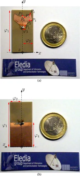
The geometry of the synthesized UWB antenna is shown in Figure 1 and, for sake of space, its geometrical parameters are reported on the photographs of the prototype. The antenna has a miniaturized planar structure of maximum extension equal to
x
z
ϕ
3ϕ
1 P4 P1 P2 P3 P5 P6 P7y
ϕ
2 (a)x
z
ϕ
4ϕ
1ϕ
2y
(b)Fig. 1. UWB Dongle Antenna geometry - (a) front view and (b) back view.
39.2 × 19.2 mm2
because of the presence of the ground plane shown in Figure 1(b). However, it should be noticed that such a
ground plane is common to the ground plane of the dongle PCB. Therefore, the part of the dongle device only concerned with the radiator turns out to be limited to an area of 16.2 × 19.2 mm2
. The UWB dongle antenna has been printed on a two-sided dielectric substrate (Arlon,εr= 3.38, thickness 0.78 mm) and it shows symmetrical properties along an axial plane orthogonal to the dielectric substrate. According to the indications reported on the picture in Fig. 1, the geometry of the antenna is defined by means of the following set of values of the descriptive parameters: ϕ1 = 39.2 mm (length of the dielectric substrate),
ϕ2 = 9.6 mm (half width of the dielectric substrate), ϕ3 = 2.1 mm (width of the input section), ϕ4 = 23.0 mm (length of the ground plane). According to the spline description [5], the remaining parts of the antenna geometry are determined by the coordinates, expressed in [mm], of the following control points: P1 = (2.1, 25.0), P2 = (6.6, 29.5), P3 = (8.6, 29.4),
P4= (7.3, 35.9), P5= (6.9, 34.9), P6= (2.2, 32.4), P7= (0.0, 33.8).
III. NUMERICAL ANDEXPERIMENTALPERFORMANCEANALYSIS
In order to experimentally test the reliability and efficiency of the synthesized radiator in an UWB communication system, a pair of antenna prototypes has been built. Moreover, the receiving and transmitting antennas have been connected to 50 Ω
rigid coaxial cables equipped with SMA connectors. More in detail, each input coaxial cable has been placed orthogonally to the dielectric substrate (i.e., to the planar structure of the antenna) and soldered across the gap between the input section
3 -25 -20 -15 -10 -5 3 3.5 4 4.5 5 |s11 | [dB] Frequency [GHz] Simulated Data Measured Data
Fig. 2. UWB Dongle Antenna - Amplitude of s11vs. frequency.
-40 -35 -30 -25 -20 -15 -10 3 3.5 4 4.5 5 |s21 | [dB] Frequency [GHz] Simulated Data Measured Data
Fig. 3. UWB Dongle Antenna - Amplitude of s21vs. frequency.
of the antenna (with width 2ϕ3) and the ground plane. This arrangement has been verified to be suitable to minimize the coupling effects with the antenna and also the contributions to the pattern of the cable radiation. The measurements have been performed with a vector network analyzer in a real environment (i.e., a non-controlled measurement scenario).
As for the electric parameters, the sij parameters have been measured at the equivalent two ports of the whole TX/RX system by placing the two antennas at a distance of 15 cm [4] (i.e., at the same distance used during the synthesis procedure
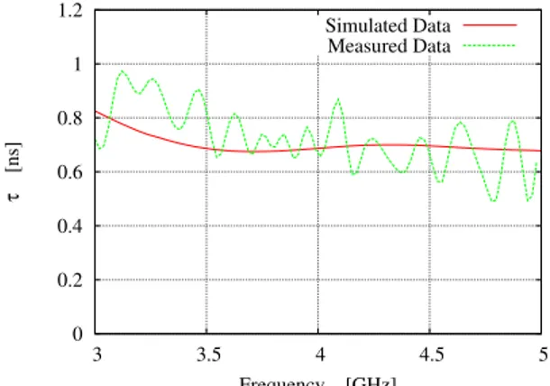
to check the distorsionless transmission of the time pulses). As shown in Fig. 2 , both measured and simulated values of the |s11| parameter turn out to be compliant with the project constraints. The differences between the two plots are due to different causes: (a) the reflection contributions added by the non-controlled measurement environment, (b) the non-uniform values of the dielectric properties of the substrate in the UWB bandwidth. Concerning the s21 parameter, Figure 3 shows the plots of experimental and numerical values of the amplitude,|s21|. As expected, the maximum variations of the amplitudes of the mutual scattering coefficient lie within the specifications (i.e.,∆ |s21|sim= 5 dB, ∆ |s21|meas = 6 dB). For completeness, Figure 4 pictorially describes the behavior of the group delay τg(f ) in the working band. As it can be observed, the project requirements are satisfied since ∆ |τg|sim= 0.1 nsec and ∆ |τg|meas= 0.5 nsec and there is an acceptable matching between numerical and experimental results. However, some discrepancies can be observed because of both reflection contributions in the measurement site and the dispersive behavior of the dielectric substrate.
As far as the radiation properties of the UWB antenna are concerned, the radiation patterns of the synthesized geometry have been numerically assessed by means of a set of simulations carried out with Method-of-Moment [8][9] based code developed at the ELEDIALab of the University of Trento. As representative examples, Figure 5 shows the normalized horizontal radiation patterns in correspondence with three different representative frequency values within the band of operation (f1= 3.0 GHz,
0 0.2 0.4 0.6 0.8 1 1.2 3 3.5 4 4.5 5 τ [ns] Frequency [GHz] Simulated Data Measured Data
Fig. 4. UWB Dongle Antenna - Group delay τg vs. frequency.
-5 0 5 10 0 90 180 270 360 Gain [dBi] φ [deg] Simulated (3.0 GHz) Simulated (4.0 GHz) Simulated (5.0 GHz)
Fig. 5. UWB Dongle Antenna - Simulated H-plane radiation pattern.
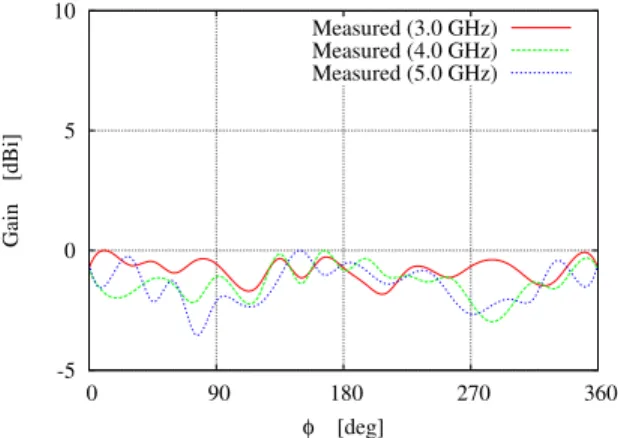
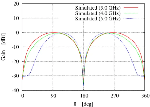
Figure 6 shows the normalized measured horizontal radiation pattern. Whatever the operating frequency, the antenna presents an omnidirectional behavior. For completeness, Figures 7 , 8 , 9 and 10 give the normalized simulated and measured vertical patterns at two orthogonal sections (i.e.,φ= 0◦andφ= 90◦). From these plots, a monopole-like behavior can be inferred. Such a conclusion further confirm the reliability and suitability of the designed antenna for mobile-like wireless dongle applications.
IV. CONCLUSION
In this letter, the structure and the performances of a miniaturized UWB antenna suitable for the integration in wireless USB dongle devices have been described. Both numerical and experimental values from a TX/RX UWB system composed by a pair of identical prototypes have been analyzed to assess the efficiency of the synthesized antenna as well as to further confirm the flexibility and the reliability of the spline-based UWB optimization. From the obtained results, besides a quite satisfactory agreement between numerical prediction and experimental measurements, a positive judgment on the antenna design for UWB dongle devices can be drawn.
ACKNOWLEDGMENTS
The authors wish to thank very much Ing. Alessandro Frattoni (Selex Communications) for his help in the experimental assessment of the antenna prototype as well as for useful comments and suggestions.
REFERENCES
[1] L. Yang and G. B. Giannakis, "Ultra-wideband communications," IEEE Signal Processing Mag., pp. 26-54, Nov. 2004.
[2] Federal Communications Commission, First Report and Order, "Revision of part 15 of the commission’s rules regarding ultra-wideband transmission systems," FCC 02-48, Apr. 2002. http://hraunfoss.fcc.gov/edocs_public/attachmatch/FCC-02-48A1.pdf
5 -5 0 5 10 0 90 180 270 360 Gain [dBi] φ [deg] Measured (3.0 GHz) Measured (4.0 GHz) Measured (5.0 GHz)
Fig. 6. UWB Dongle Antenna - Measured H-plane radiation pattern.
-40 -30 -20 -10 0 10 20 0 90 180 270 360 Gain [dBi] θ [deg] Simulated (3.0 GHz) Simulated (4.0 GHz) Simulated (5.0 GHz)
Fig. 7. UWB Dongle Antenna - Simulated E-plane radiation pattern (φ = 0◦).
[3] Wireless USB Promoter Group [Online], Available at http://www.usb.org/developers/wusb/.
[4] X. Qing, Z. N. Chen, and M. Y. W. Chia, "Characterization of ultrawideband antennas using transfer functions," Radio Sci., vol. 41, RS1002, 2006.
[5] C. de Boor, A Practical Guide to Spline. Springer, New York, 2001.
[6] L. Lizzi, F. Viani, R. Azaro, and A. Massa, "Optimization of a spline-shaped UWB antenna by PSO," IEEE Antennas Wireless Propagat. Lett., vol. 6, pp. 182-185, 2007.
[7] L. Lizzi, F. Viani, R. Azaro, and Andrea Massa, “A PSO-driven spline-based shaping approach for Ultra-Wideband (UWB) antenna synthesis,” IEEE
Trans. Antennas Propagat., in press.
[8] R. F. Harrington, Field Computation by Moment Methods. Malabar, FL: Robert E. Krieger, 1987.
-40 -30 -20 -10 0 10 20 0 90 180 270 360 Gain [dBi] θ [deg] Simulated (3.0 GHz) Simulated (4.0 GHz) Simulated (5.0 GHz)
Fig. 8. UWB Dongle Antenna - Simulated E-plane radiation pattern (φ = 90◦).
-40 -30 -20 -10 0 10 20 0 90 180 270 360 Gain [dBi] θ [deg] Measured (3.0 GHz) Measured (4.0 GHz) Measured (5.0 GHz)
Fig. 9. UWB Dongle Antenna - Measured E-plane radiation pattern (φ = 0◦).
-40 -30 -20 -10 0 10 20 0 90 180 270 360 Gain [dBi] θ [deg] Measured (3.0 GHz) Measured (4.0 GHz) Measured (5.0 GHz)