Universit`
a degli Studi di Camerino
School of Science and Technology Physics Division
Reaction Mechanisms in Advanced Materials for
Li and Na-ion Batteries Studied by X-ray
Absorption Spectroscopy and Related Techniques
Doctoral Course in
Theoretical and Experimental Physics Cycle XXXI
Candidate Supervisor
Matteo Ciambezi Prof. Andrea Di Cicco
Abstract
The research work presented in this thesis regarded the structural study of different materials employed as battery electrodes (for both Li and Na ion cells) by means of X-ray Absorption Spectroscopy (XAS), X-ray Photoelectron Spectroscopy (XPS) and Raman Spectroscopy. The main purpose of the thesis was to provide better insight, at a microscopic and atomic level, of all the mechanisms related to the insertion/de-insertion of lithium or sodium ions in the electrode structure at the electrolyte interface and the bulk. In particular we have tackled three main open problems concerning: i) the evolution of the local structure in zinc-ferrite conversion-alloying materials used in lithium-ion batteries, ii) the study of formation and evolution of the solid electrolyte interphase (SEI) in carbon-based anodes again used for lithium-ion cells, iii) the rela-tionship between local structure distortion and electrochemical performances in a class of cathode materials for sodium-ion batteries.
By using X-ray absorption spectroscopy, we have shown that in the very early stages of Li+ insertion (until 0.3 Li+ per formula unit) carbon-coated zinc-ferrite nanoparticles anode retain the spinel structure while at higher level of Li uptake (> 0.3 Li+ per formula unit), Zn atoms migrate to vacant crystallographic sites. In this initial stage, Fe is found to be gradually reduced from Fe3+ to Fe2+ upon lithium insertion and remains in the original octahedral sites. Our EXAFS study indicates an increase in structural disorder upon lithiation. Lithiation proceeds with a continuous reduction of the Zn and Fe until those species are fully metallized in the form of nano-sized particles. Finally, we could provide direct proof of the reversible lithium-zinc alloying mechanism occurring in the very final stage of the lithiation.
The evolution and stability of the SEI were studied using an arsenic-containing compound as electrolyte. Arsenic acts as local probe for SEI formation for XAS and XPS, giving an insight into the oxidation state and structure of the SEI. Both XAS
iv
and XPS revealed the presence of arsenic with oxidation state 3+ and 5+, possibly in the form of arsenic oxides (As2O5, As2O3) and arsenic-fluorine compounds (AsF3, AsF6
–, Li
xAsF3-x). Moreover, XPS revealed the presence of As
0 (not detected by XAS) that could be present, in a small quantity, only on the outer layer of the SEI. The organic fraction of the SEI has been also studied with XPS, showing the presence of different lithium alkyls species and carbonates as a result of the degradation of the electrolyte organic solvents. Those species may contain lithium atoms contributing to the total capacity of the cell, in agreement with recent results. In-situ micro-Raman experiments, specifically developed during this thesis, were attempted showing the modifications of the graphitic host structure during lithium insertion in the material. Finally, the structure of Mn-based layered oxides for sodium-ion cathodes, doped with Ti and Fe, was studied by X-ray Absorption Spectroscopy. We have verified that the oxidation states of Mn and Ti in P2-Na2/3Mn0.8Fe0.2-xTixO2 are in agreement with the expected theoretical values. Our structural XAS refinement, compared with the results of DFT calculations and XRD data, confirmed experimentally the Jahn-Teller induced distortion of the structure for all the materials under consideration. A slight decrease of the local structural disorder is observed in the material where both Fe and Ti are present with equal proportions.
Most of the results presented in this thesis have been published in international journals, and the reader is referred to the published papers for further details.
Ringraziamenti
Desidero ringraziare il Prof. Andrea Di Cicco, supervisore della mia tesi di dottorato, per avermi concesso l’opportunità di affacciarmi al mondo della ricerca scientifica. Senza le sue indicazioni e supporto questo lavoro non sarebbe stato possibile.
Un grazie particolare ad Angela e Marco: indispensabili per me sia per i preziosissimi consigli e l’aiuto a svolgere il mio lavoro, sia per avermi sempre saputo incoraggiare ed ascoltare.
Ringrazio tutto il gruppo di Francesco Nobili, in particolar modo Marta, per la pazienza che hanno avuto nella costante collaborazione e per avermi insegnato e concesso l’utilizzo delle apparecchiature nel loro laboratorio.
Grazie ad i compagni di laboratorio, amici, colleghi dottorandi e non (Fabio, Matteo, Sara, Catia, Emin, Michele, Rahul, ...) per gli innumerevoli caffè, pranzi e "pause disperazione" passati insieme.
Un grazie immenso a Mamma, Babbo e Leonardo che mi hanno sempre dimostrato che posso contare su di loro, anche nei momenti di lontananza.
In fine un grazie speciale a Giulia che mi è stata vicina soprattutto nei periodi più frenetici e stressanti. Grazie per essere stata comprensiva nei momenti di mio maggiore impegno e per avermi dato incoraggiamento, conforto ed amore.
Contents
Abstract iii
Ringraziamenti v
1 Introduction 1
1.1 The Climate Change Challenge . . . 1
1.1.1 Paris Agreement . . . 2
1.2 Energy Policies against Climate Change and Renewable Energies . . . . 2
1.2.1 Role of Energy Storage Systems . . . 3
1.3 Purpose of this Thesis . . . 4
2 Electrochemical Storage Systems 9 2.1 Basic Concepts of Batteries . . . 9
2.2 Lithium-ion Batteries . . . 12
2.2.1 Anode Materials . . . 16
2.2.2 Cathode Materials . . . 21
2.2.3 Electrolytes for LIBs . . . 24
2.3 Sodium-ion Batteries . . . 26
2.3.1 Anode Materials . . . 29
2.3.2 Cathode Materials . . . 32
2.3.3 Electrolytes for NIBs . . . 35
2.4 Solid Electrolyte Interface (SEI) . . . 36
2.4.1 Formation and Features of SEI . . . 36
2.5 The Solid Permeable Interphase (SPI) . . . 40
3 Experimental Techniques 43 3.1 X-ray Absorption Spectroscopy . . . 44
viii CONTENTS
3.1.1 XANES and EXAFS in the Study of Atomic and Electronic
Structure of Materials . . . 47
3.1.2 Experimental modes . . . 50
3.2 X-ray Photoelectron Spectroscopy (XPS) . . . 51
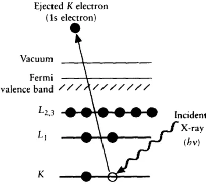
3.2.1 Qualitative and Quantitative Interpretation of the XPS Spectrum 52 3.2.2 Auger Electron Spectroscopy . . . 55
3.3 Raman Spectroscopy . . . 59
3.3.1 Raman Set-up . . . 61
3.3.2 Raman Spectroscopy for the Study of Electrode Materials . . . 63
3.4 Electrochemical Techniques . . . 64
4 Lithiation Mechanisms in zinc-iron oxide Electrodes 69 4.1 Introduction . . . 69
4.2 Experimental Characterizations and Synthesis Procedure for ZFO-C . . 71
4.3 Preliminary Morphological and Structural Characterization . . . 72
4.3.1 Spinel Ferrite Structure . . . 73
4.4 Electrochemical Characterization . . . 74
4.4.1 Galvanostatic Tests and Cycling Performances . . . 74
4.4.2 Cyclic Voltammetry . . . 74
4.4.3 Voltage Profile of the First Galvanostatic Discharge and Expected Reactions and Structural Modifications . . . 76
4.5 Experimental Set-up for in-situ and in-operando XAS . . . 77
4.5.1 Pouch Cell for in-situ XAS in Transmission Mode . . . 78
4.5.2 X-ray Absorption Spectroscopy Experiment . . . 79
4.6 XAS Analysis and Results . . . 82
4.6.1 XANES . . . 82
4.6.2 EXAFS . . . 85
4.6.3 Initial Lithiation Phase . . . 86
4.6.4 Full Lithiated Phase . . . 92
5 Formation and Evolution of the Interface in Graphite Anodes 97 5.1 Aim of this Research . . . 97
5.2 Experimental . . . 98
5.2.1 Samples Preparation . . . 98
5.3 Results from Previous XAS Analysis . . . 99
CONTENTS ix
5.3.2 EXAFS Analysis . . . 102
5.4 XPS Analysis . . . 103
5.4.1 Calibration of XPS Spectra and Determination of the Auger Parameter . . . 104
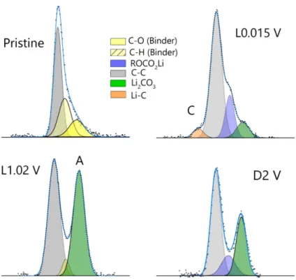
5.4.2 Analysis of Carbon 1s Lines . . . 105
5.4.3 Analysis of Lithium 1s Lines . . . 108
5.4.4 Analysis of Arsenic 3d Lines . . . 110
5.5 Raman Spectroscopy Analysis . . . 114
5.5.1 MicroRaman Set-up for in-situ Analysis . . . 114
5.5.2 In-situ Electrochemical Cell . . . 114
5.5.3 Preparation of the Self-Standing Electrodes . . . 116
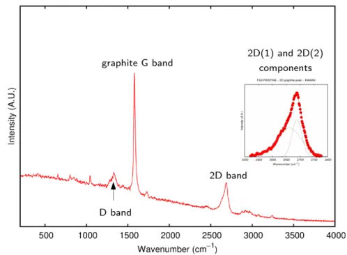
5.5.4 Raman Experiment and Results . . . 116
6 Local Structure of Advanced Cathodes for Na-ion batteries 121 6.1 Background on Material Properties . . . 121
6.2 Preliminary Characterization . . . 123
6.2.1 X-ray Diffraction . . . 123
6.2.2 Electrochemical Performances . . . 125
6.2.3 Structural Determination from ab-initio Calculations . . . 126
6.3 Experimental - XAS . . . 129
6.4 XANES . . . 129
6.5 Modelling the Structure . . . 130
6.6 EXAFS Analysis . . . 131
7 General Conclusions 135 List of Publications 138 Author’s Contributions to the Experiments and Analysis . . . 139
Conferences and Schools 141 Appendix 143 A XAS Data-Analysis 143 A.1 Absorption cross section . . . 143
A.2 Analytical expression for EXAFS signal . . . 145
A.4 n-body decomposition . . . 151
Chapter 1
Introduction
1.1
The Climate Change Challenge
Climate change can be defined as the greatest health challenge of the 21samazfitt century [1]. The severity of the direct impact of climate change over human society and health is day by day more evident and clear. In fact, in the recent years, the public health community has rapidly agreed on the causal connection between climate change and health risks, with a better understanding of the factors that link these two issues, increasing the awareness on the significant health threats and offering possible solutions to avoid the worst impact [1].
Climate change impacts human health both directly and indirectly. The direct impact includes physiological effects from exposure to higher temperatures such as respiratory and cardiovascular diseases, and also injuries and death caused by the exposition of the population to extreme weather events such as heat-waves, severe flooding, wildfires and tropical storms; with a high impact on the global risk of populations. The indirect impact is related to the long-term modification of the local environment, with the possible degradation of air, water and soil quality that may cause climate-related displacement, immigration phenomena and conflicts [1,2].
The drivers of climate change are for the big part derived from the combustion of fossil fuels and the subsequent emission of air-pollutant and greenhouse gases, which are emitted from several sectors: housing, transport, energy and agriculture [3].
2 Introduction
1.1.1
Paris Agreement
In December 2015, the Paris Agreement [4] was adopted under the United Nations Framework Convention on Climate Change (UNFCCC) to combat the climate change [5]. It is the first climate agreement to obtain strong global support, and being now ratified by 183 countries [6]. Within this agreement, countries submitted national plans to address the climate change challenge after the year 2020; the main goal of Paris Agreement is to hold "the increase in the global average temperature to well below 2◦C above pre-industrial levels and to pursue efforts to limit the temperature increase to 1.5◦C above pre-industrial levels" [4]. This temperature goal represents the level of climate change that governments agree would prevent dangerous and irreversible interference with the climate system, while ensuring sustainable economic development and food production [5,7,8].
The Agreement allows each country to set their national targets and also supports low- and middle-income countries by a founding mechanism with a US$ 100 billion annual funding system [6]. This will allow all countries to find the most appropriate ways to overcome the issue of climate change while ensuring that all parties contribute to meet global goals [1].
Thus, Paris Agreement can be defined as the most important health agreement of this century [1], since it addresses not only the direct health risks, but also has the potential to bring strong positive changes and benefits in the industry, transport and energy sectors, since the proposed policies will widely and strongly influence social, cultural, economical, climate and environmental human activities [3].
1.2
Energy Policies against Climate Change and
Renewable Energies
Currently, the big part of used energy source derives from fossil fuels. To fulfil the goals of Paris Agreement is necessary to perform a transition to affordable, reliable, sus-tainable and modern energy sources with zero greenhouse gases emission [1]. Nowadays the share of renewable energy sources is only 25% of the global electricity production [9], despite the fact that the cost of renewable energy production is falling quickly, and investments are growing fast. In order to successfully meet the goal of maintaining the global temperature 2◦C above pre-industrial levels, the cut of renewable energy must be at least 65% [10].
1.2 Energy Policies against Climate Change and Renewable Energies 3
Therefore, the policies on energy are based on scaling up renewable energy sources. In particular cutting down the share of energy derived from coal which represents more than 40% of CO2 emission. Policy should, thus, ensure to phase out coal use as quickly as possible while ensuring a smooth transition to more eco-friendly sources.
The transport sector gives also another significant contribution to both greenhouse gas emissions and local air pollution. It is accountable for about 23% of the total energy-related greenhouse gas emissions globally [11]. More sustainable means of transport will include the employment of electric vehicles and encouraging the use of public transportation.
Nowadays private vehicles represent the main and more common means of transport worldwide and the most part of those employs heat engines running on petrol or diesel fuel; both emit greenhouse gases and also particulate which contribute to poor air quality. Even if there is a big increment in the number of electric vehicles (+50% between 2016 and 2017) they still represent a small number in the total of the global vehicle fleet. [11].
1.2.1
Role of Energy Storage Systems
The main issue with renewable energies is that the production is not constant nor always available. Most of renewable energy sources are, in fact, influenced or depend on external and natural phenomena, and cannot provide an immediate response to the demand since they are not easily adjustable to consumption needs. The unpredictable character of these sources requires that network provisioning and usage regulations be established for optimal system operation [12].
Delocalized electricity production and the use of time-fluctuating sources (wind turbines, solar, etc.) increase the difficulty of stabilizing the power network, due to an imbalance in supply/demand. Therefore may be convenient to produce the energy, transmit it, convert it and store it in case of surplus production in order to use the stored energy in times of higher demands [12].
Alongside to flexibility, Electrical Energy Storage (EES) will play a crucial role in the transition to low-carbon energy system. The International Energy Agency estimates that to fulfil the Paris Agreement it will be necessary to increase the energy storage capacity from the 140 GW of 2014 to 450 GW in 2050 [14]. This increase is furthermore necessary, as the European Commission underlined, to ensure the internal energy security and energy internal market. By using more EESs, the European Union can decrease its energy imports, improve the efficiency of the energy system and keep
4 Introduction
Figure 1.1: Globally installed energy storage capacity, 1978-2016, excluding pumped hydro
storage [13]
the prices low [13].
At the present day, EES contribute to 10% of the installed generation capacity in Europe, where hydroelectric pumped storage is by far the most used storage technology. Many others EESs such as compressed air storage, flywheels, electrochemical (batteries) and thermal are available and can be competitive depending on the requirements of the application [15].
The largest representative of EESs for stationary applications (but also increasing in the automotive sector) is electrochemical storage or batteries that can store energy in a chemical form and convert it into electricity when needed. A more precise description of this class of EESs will be given in Chapter 2.
1.3
Purpose of this Thesis
As seen in the previous sections, electrochemical storage system is a crucial sector with a growing importance for a wide range of applications: from mobile electronic device energy storage, powering the future automotive fleet, and finally for micro-grid storage applications.
1.3 Purpose of this Thesis 5
recent (first commercial prototype were presented in the ’90s) and presents a large margin of development. In particular, present research efforts, are focussed on increasing the capacity, energy density and durability; while at the same time improving safety, reliability, eco-friendliness and recyclability of the materials.
To pursue that, is fundamental to have a deeper and precise understanding of all the mechanisms that occur during the various chemical reactions and also at the structural level of the different active materials adopted. A description of electrochemical storage systems and relevant materials is presented in Chapter 2.
Within this scenario, I present my original doctoral thesis work. It collects the research activities carried out during the three years of my Ph.D. at the University of Camerino (Italy) under the supervision of Professor Andrea Di Cicco and during my six month visit period at the energy research center CIC EnergiGUNE in Vitoria (Basque Country - Spain) under the supervision of Doctor Miguel Àngel Muñoz-Màrquez. Moreover, part of the experimental work has been also carried out in Synchrotron Radiation facilities such as ESRF (Grenoble), Elettra (Trieste) and Soleil (Paris).
The thesis investigates structural properties and modifications occurring both on the surface of the electrodes and in the bulk of the electrochemical active materials, with a particular focus on the development of in-situ and in-operando experimental techniques, which allows to get a deeper understanding of the several and complex evolution processes occurring during the electrochemical-induced redox reactions. To achieve that, we employed several X-ray and optical spectroscopic techniques. In particular, X-ray Absorption Spectroscopy, X-ray Photo-emission Spectroscopy and Raman Spectroscopy; those techniques, when combined, result complementary one to each other, and are an optimal way to obtain both information regarding the surface of the material and the bulk. In particular X-ray Absorption Spectroscopy and X-ray Photo-emission spectroscopy are used in a large variety of research fields since they are element specific techniques and provide information about the local structure and the electronic structure around the single atomic sites also in complex systems. The description of the various experimental techniques adopted in this thesis is summarized in Chapter 3.
The first part of the original thesis work, presented in Chapter 4, concerns the study of the structural evolution in anodes for lithium-ion batteries composed of carbon-coated zinc-ferrite (ZnFe2O4) nanoparticles as active material. This is one member of a new
6 Introduction
developing class of battery material with very promising performance, cost-effectiveness, ecological and safety characteristics: conversion/alloying materials. These materials employ a completely different reaction process if compared with standard and currently commercially available Li-ion cells; this mechanism involves major modification and re-organization of the material internal structure, leading to a full reduction and oxidation processes (of iron and zinc for ZnFe2O4 anodes) in order to store and de-insert lithium ions from the host electrode. These changes are not trivially investigable with commonly available laboratory techniques (X-ray Diffraction for example) due to the formation of amorphous phases and nano-crystallites. To overcome this issue, we performed different synchrotron-based X-ray Absorption Spectroscopy experiments, both on ex-situ samples (cycled electrodes, extracted from the Li-ion cell, sealed and measure) and in-situ/in-operando cells (experiments were performed in parallel with the operational cycles of the half-cell). For this material, it was important to have a better insight and a confirmation of the expected electrochemical reactions, in particular, to verify the final reversible alloying reactions between lithium and zinc which could provide an extra capacity storage for the material.
Chapter 5 is focused on the analysis of the interface which forms onto the electrode (referred as Solid Electrolyte Interphase - cfr. Chapter 2), mostly during the first lithiation/de-lithiation cycle. This interface is a crucial component of modern Li-ion and Na-ion battery cells since it acts as a protective layer, avoids further decomposition of the electrolyte and has a fundamental role on stability and cyclability of the battery. This aspect gained, in recent years, the attention of the scientific community. In particular, this research activity is a prosecution of the European project "Stable Interfaces for Rechargeable Batteries" (SIRBATT) in which my research group was involved. In this work we carried out X-ray Absorption Spectroscopy analysis of electrodes, obtaining information regarding the thickness, the oxidation state and structure of the interface. Moreover, my research activity included also the interfacial analysis of graphite anodes and the study of the formation processes and evolution of the SEI layer when using non-conventional electrolytes (LiAsF6). Here I present a detailed X-ray Photo-spectroscopy analysis, performed on ex-situ samples, of such interface; providing supplementary and complementary details to the previous analysis.
The final part of the thesis, reported in Chapter 6, is devoted to sodium-ion battery materials. This work was done in close collaboration with CIC EnergiGUNE, and my original contribution was mainly the structural analysis of manganese-based P2-phase layered cathodes Na2/3Mn0.8Fe0.2O2, Na2/3Mn0.8Fe0.1Ti0.1O2, and Na2/3Mn0.8Ti0.2O2
1.3 Purpose of this Thesis 7
used in Na-ion cells. The analysis was focussed on understanding the role of non-electrochemical active species used as dopants (Fe and Ti) which can provide a huge improvement in the cell performances. The X-ray Absorption Spectroscopy was used to identify subtle structural modifications induced by the presence of such dopants which result in a deformation of the initial structure in the form of Jahn-Teller elongation.
Chapter 2
Electrochemical Storage Systems
2.1
Basic Concepts of Batteries
A battery is an electrochemical power source which converts chemical energy into electrical energy. At least two reaction partners undergo a chemical oxidation-reduction (redox) process during this operation. The energy of this reaction is available as electric current at a defined voltage and time [16]. The redox reaction involves the transfer of electrons from one material to another through an electric circuit and the restoring of charge neutrality through electrolyte migration [17]. The basic element of a battery is called cell. These can be connected in series, in parallel or both depending on the desired output voltage and capacity. The main constituents of a cell are:
• The anode or negative electrode: this is the reducing electrode which gives up electrons to the external circuit and is oxidized during the electrochemical reaction. It must have high efficiency as reducing agent, and high coulombic output (Ah/g), and be chemically stable.
• The cathode or positive electrode: this is the oxidizing electrode, it accepts electrons from the external circuit and is reduced during the electrochemical reaction. It must be an efficient oxidizing agent, stable when in contact with the electrolyte, and have a useful working voltage.
• The electrolyte: this is the ionic conductor, which provides the medium for transfer of charge, as ions, inside the cell between the anode and the cathode. Usually, the electrolyte is in a liquid form, made of solvents with dissolved salts, acids, or alkalies to impart ionic conductivity. There exist also solid electrolytes [16], that
10 Electrochemical Storage Systems
are ionic conductors at the operating temperature of the cell. The electrolyte must have good ionic conductivity but not be electronically conductive, as this would cause internal short-circuiting; it must also be inert to the electrodes materials.
Physically the anode and cathode electrodes are electronically isolated in the cell to prevent internal short-circuiting but are surrounded by the electrolyte. In battery cells, a separator material is employed to divide the anode and cathode electrodes mechanically. The separator, however, is permeable to the electrolyte in order to maintain the desired ionic conductivity. In some cases, the electrolyte is immobilized for a non-spill design. Electrically conducting grid structures or materials may also be added to the electrodes to reduce internal resistance [17]. The electrochemical features of a battery are described by the following parameters:
• Capacity (Q): The theoretical capacity of a cell is determined by the quantity of active materials in the cell. It is expressed as the total quantity of electricity involved in the electrochemical reaction and is defined in terms of coulombs (C) or ampere-hours (Ah).
Q= I · t = x · n · F (2.1)
where I is the current drawn from the battery, t is the amount of time (in hours) that a battery can sustain; x is the number of moles of active material, n is the number of electrons involved in the reaction and F is the Faraday constant. Usually the capacity is normalized to the electrode weight (Ahg−1) or volume. • Energy (E): The capacity of a cell can also considered on an energy (watt hour)
basis by taking both the voltage and the quantity of electricity into consideration,
E = Q · V (2.2)
This is the theoretical maximum energy that can be delivered by the electrochem-ical system.
• Power (P): is simply the energy per unit time, or the voltage times the current.
2.1 Basic Concepts of Batteries 11
Electrochemical cells are identified as primary (non-rechargeable) or secondary (recharge-able). A schematics of volumetric vs. gravimetric energy density is shown in Fig.(2.1) for various secondary battery technologies [18].
Figure 2.1: Volumetric and gravimetric energy density of different secondary battery
tech-nologies [18].
Primary batteries
These batteries are not capable of being easily and effectively recharged; hence, once discharged they are disposed. The reaction in these cells is irreversible. Primary batteries are usually inexpensive, have a good shelf life, high energy density and require no maintenance.
Secondary batteries
These batteries can be recharged several times. Only reversible electrochemical reactions offer such a possibility. After the cell is discharged, an externally applied electrical energy forces a reversal of the electrochemical process; as a consequence the reactants are restored to their original form, and the stored electrochemical energy can be used
12 Electrochemical Storage Systems
Table 2.1: Voltage, capacity and specific energy of major primary battery systems [17]. Battery type Anode, cathode V Ah/kg W h/kg
Alkaline Zn, MnO2 1.5 224 358 Mercury Zn, HgO 1.34 190 255 Silver oxide Zn, Ag2O 1.6 180 288 Zinc / O2 Zn, O2 1.65 658 1085 Li−SO2 Li, SO2 3.1 379 1175 Li−MnO2 Li, MnO2 3.5 286 1001
once again by a consumer. The process can be reversed hundreds or even thousands of times, so that the lifetime of the cell can be extended. This is a fundamental advantage, especially as the cost of a secondary cell is normally much higher than that of a primary cell. Furthermore, the resulting environmental friendliness should be taken into account [16].
Table 2.2: Voltage, capacity, specific energy and cycle life of major secondary battery
systems [17].
Battery type Anode, cathode V Ah/kg W h/kg Cycle life
Lead-acid Pb, PbO2 2.1 120 252 >1000 Nikel-cadmium Cd, Ni oxide 1.35 181 244 >200
Nikel-metal hydrite MH, Ni oxide 1.35 178 240 >300
Lithium-ion LixC6, Lii-xCoO2 4.1 100 410 >1200
2.2
Lithium-ion Batteries
Lithium is the lightest of all metals, has the greatest electrochemical potential (−3.04 V vs standard hydrogen electrode) and provides the highest specific energy per weight. For these reasons, starting from the 1970s, the first primary Li cells (based on metal lithium anodes) began to be developed and commercialized. First attempts to develop rechargeable lithium batteries followed when several inorganic compounds (later defined intercalation compounds) demonstrated to reversibly react with alkali metals [18,19]. In 1972, Exxon [20,21] started to prototype the first rechargeable Li using layered TiS2 as positive electrode, Li metal as negative electrode and lithium perchlorate in dioxalane as electrolyte. Nevertheless, the commercialization of such prototype was not successful due to the shortcoming of Li-metal and liquid electrolyte combination causing the growth of Li dendrites [22] as metal was plated during the
2.2 Lithium-ion Batteries 13
discharge-recharge cycles. This phenomenon could lead to short-circuit between the electrodes and subsequently posing thermal runaway and explosion hazards.
In order to solve safety issues, it has been proposed to substitute Li-metal with a second insertion material in which Li-ions are stored in the layers of a suitable host [23]; the presence of Li in its ionic rather than its metallic state solved the problem of dendrites formation. The new cell concept was first demonstrated by Murphy et al. [24] and later by Scrosati et al. [25] between the end of the 1980s and the beginning of 1990s, and led to the so-called Li-ion or rocking-chair battery technology.
Figure 2.2: Schematic representation of rechargeable Li-ion battery [18].
Almost two decades to develop the concept of Li-ion cell and to obtain a reliable and safe commercializable prototype were due to the difficulties in finding suitable materials for negative electrode (insertion compounds or Li alloys) and in finding electrolytes which met, besides safety concerns, the cost and performance requirements for a successful battery technology. A schematic representation of a rechargeable Li-ion cell is shown in Figure 2.2.
In 1981, Goodenough first proposed layered LiCoO2 as high energy and high voltage cathode material [26]. However, this did not attract much attention due to the lack of a safe anode material which limited the application of layered oxide cathodes of LiMO2 (M = Ni, Co). In the same period Besenhard [27], Yazami [28] and Basu [29] discovered that graphite could be a good candidate to reversibly store Li ions by intercalation/deintercalation. Only at the end of the decade, in 1987, Yoshino et al. [30] filed a patent and build a prototype cell using carbonaceous anode and LiCoO2cathode; both materials are stable in air which simplifies the engineering and manufacturing
14 Electrochemical Storage Systems
processes [31]. The large-scale manufacturing of similar Li-ion batteries (LIBs) started in 1991 by Sony Corporation [32]. Batteries with similar design are still present nowadays, almost after 30 years, becoming the standard for high-performance and portable electronic devices [18].
The major advantages and disadvantages of LIBs compared to other battery tech-nologies are listed in Table 2.3. The high specific energy (∼ 150 Wh/kg) and energy density (∼ 400 Wh/L) of commercial LIBs make them perfectly suitable for applica-tions where volume and weight must be minimized [17]. LIBs offer a low self-discharge (2 − 8% per month) long cyclability (more than 1000 cycles) and a broad temperature range of operation (charge −20◦/60◦C, discharge −40◦/65◦C) extending the usage in a variety of applications [17]. Single cells operate in the range of 2.5 to 4.2 V, almost three times that of NiCd or NiMH cells, allowing fewer cells for a given voltage. Also, the high rate capability has been demonstrated (discharge at 5C continuous or 25C pulse). These combined qualities, with the relative cost-effectiveness, are the key of LIBs success.
Main disadvantages of Li-ion batteries consist in over-charge and over-discharge effects which may degrade the cells, this can be avoided by the use of an electronic management circuitry that protects the system from extreme charge and temperature conditions; also LIBs permanently lose capacity at elevated temperatures (< 65◦C).
Table 2.3: Advantages and disadvantages of LIBs [17].
Advantages Disadvantages
High specific energy and energy density Moderate initial cost
Long cycle and shelf life Degradation at high temperatures
Low self-discharge Capacity loss or thermal runway if overcharged High rate and power capabilities Ageing effect
High coulombic and energy efficiency Need for protective circuitry
No memory effect Venting and thermal runway when crushed A commercial Li-ion battery is composed by graphite as anode and LiCoO2 as cathode. The ionic conduction is achieved by the electrolyte, usually consisting of a lithium salt (for example LiPF6 dissolved in a mixture of organic solvents (ethylene carbonate/dimethyl carbonate: EC/DMC). The two electrodes are physically separated by a micro-porous separator which allows the ionic flow and prevents internal short circuits. Other materials such as binders and fillers can be added to the cell in order to improve the conductivity, the stability or the cell chemistry.
2.2 Lithium-ion Batteries 15
The electrodes are usually wet-coated onto the current collectors: a foil of metal which has to be electrochemically stable in the potential operation window of the electrodes [33]. Usually, a copper foil is adopted as anode current collector, since it does not react with lithium ions at low potentials, aluminium foil can be used as cathode current collector because it is chemically stable at cathodic potentials, while it would form lithium alloys at the lower anodic potentials.
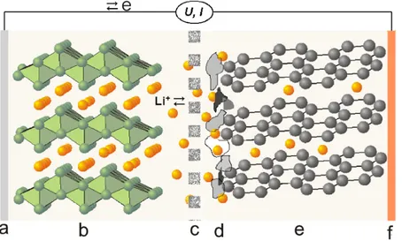
Figure 2.3: Schematic illustration of a typical Li-ion battery: a) aluminium current collector;
b) oxide positive electrode material; c) porous separator soaked with liquid electrolyte; d) inhomogeneous SEI layer; e) graphite electrode material; f) copper current collector. Image by Verma et al. [34].
The working mechanism of a lithium-ion cell is schematized in Figure 2.3: during the discharge process, lithium atoms intercalated into graphite layers undergo an oxidation reaction. The positively charged lithium ions are dissolved in the electrolyte and flow into the the lattice of LiCoO2 cathode. At the same time also electrons flow towards the positive electrode though an external circuit to power various systems. At the positive electrode, Li-ions recombine with the electrons and fill up the available sites into the cathode host matrix via a reduction reaction process. If the current is forced to flow in the opposite direction, by applying an external electromotive force, the redox reaction is reversed, and the battery is in a charging state. Following are listed the main reactions occurring on the positive electrode and negative electrode [17]:
Positive: LiMO2 −−−−−*)−−−−−charge−
discharge Li1-xMO2+ xLi
16 Electrochemical Storage Systems
Negative: 6 C + xLi++ xe– −−−−−*charge )−−−−−−
discharge LixC6
Overall: LiMO2+ C−−−−−*)−−−−−charge−
discharge LixC + Li1-xMO2
2.2.1
Anode Materials
The negative electrode in LIBs must accept Li+ ions during charge, and release them into the ionic flow during the discharge. The three basic requirements for anode materials are: low electrochemical potential versus Li/Li
+, high amount of lithium accommodable, long structural stability after several cycles of charge/discharge. It is possible to classify the various materials in three main categories, depending on the different lithiation mechanism (Fig. 2.4).
Figure 2.4: Different reaction mechanisms in anode materials for LIBs [35].
Insertion Anodes
2.2 Lithium-ion Batteries 17
Carbon-based materials, with various morphologies, are largely used for commercial LIBs due their features: large availability; thermal. chemical and electrochemical stability, low cost and good reversibility for lithium intercalation and de-intercalation [36, 37]. The main distinction within carbonaceous materials can be made between
graphitic carbons and non-graphitic carbons [38]. A schematic of the structures and
discharge profiles is shown in Figure 2.5.
Figure 2.5: Scheme of: (a) soft carbons, (b) hard carbons, (c) graphitic carbons; and their
typical potential profiles [39].
Graphite and graphitic carbons are composed by graphene layers (extended sheets of sp2-hybridized carbon atoms arranged in hexagonal rings) stacked in AB or ABC layers held together by Van der Waals force [39]. During charge and discharge, lithium ions intercalate in between the layers by a so-called staging mechanism, ending with an AA stacking configuration once the material is fully litiathed [39–42]. The sp2-hybridization,
p-orbitals forming a delocalised electron network, also bring a big advantage in terms
of electric conductivity of the material [38]. Intercalation of Li-ions into graphite layers consists in the insertion of one lithium-ion every six carbon atoms, thus graphite has a theoretical capacity of 372 mAhg–1. This process occurs through the formation of different stages depending on the increasing ratio Li/C and corresponding to three well-defined potential plateaus in the potential window 0.05 − 0.25 V shown in Figure 2.5 (c). The co-intercalation of solvents present in the electrolyte can, within several
18 Electrochemical Storage Systems
cycles, cause the exfoliation of the layers in graphite and drive to battery failure [43] Non-graphitic carbons consist of carbon atoms, arranged in the usual hexagonal network, but without a crystallographic order along the vertical axis, and they can be divided in soft and hard carbons, depending on their behaviour during heat treatment. Insertion of lithium into non-graphitic carbons cause negligible expansion of interlayer spacing, thus the volumetric deformation of the electrode is minimal. Both soft and hard carbons show a sloping potential-capacity curve with no significant plateaus. These carbons show a higher specific capacity with respect to graphite because the different structure and morphology allow alternative ways for lithium to be adsorbed by the material. For example, it can be stored on both sides of each layer of non-stacking graphene layers [40], in the micro-pores [38] and in other micro-structures of the material. Nevertheless, a certain fraction of lithium that has reacted with carbon during lithiation, cannot be recuperated in the charging process. Some of the Li atoms may, in fact, remain trapped in the micro-structures and internal porosity of non-graphitic carbons [43]. Part of the irreversible capacity is due to the formation of a surface film around the carbon particles (cfr. Section 2.4).
Alloying Anodes
Several elements are able to reversibly form alloys with lithium at a low potential, room temperature and in non-aqueous electrolytes. Sn, Pb, Al, Sb, Zn, Si are between the most studied due to their abundance, low cost and eco-friendliness, and, most important, for their appealing theoretical capacity. They can be used in the electrodes in their metallic state or as oxides. The generic reaction for element A can be written as: xLi + A lithiation −−−−−−−* )−−−−−−−− de−lithiation xe −+ xLi+A
The most important issue for these materials is the large volume expansion/contraction upon (de-)lithiation (even more than 200% volume increase), which will cause, after several cycles, the rupture of the active material and, consequently, a loss of electronic contact and finally the pulverization of the electrode [39,44], causing an irreversible loss of capacity. To overcome this capacity loss, several strategies have been attempted: one is to use a host matrix which acts as a buffer to contain this large volume change in order to maintain the electrode integrity and electronic contact. This can be achieved in various ways, for example, using hollow carbon nano-spheres, core-shell nano-structure and micro-sized carbonaceous matrices (cfr. the review by Loeffer et al. [39]). Despite
2.2 Lithium-ion Batteries 19
the promising approaches and the appealing performances of alloying anodes, only tin-based materials have been successfully adopted for commercial LIBs, also silicon-tin-based anodes (carbon-coated silicon nano-structure) have recently appeared into commercial LIBs [45].
Conversion Anodes
Conversion materials MaOb (M = Co, Fe, Ni, Mn, Cu, etc.) undergo a solid-state redox reaction during (de-)lithiation, in which there is a change in the crystalline structure, accompanied by a breaking and recombination of chemical bonds [46]. Initially, these kinds of displacement reactions were considered to be irreversible at room temperature due to the high energy needed for bond breakage, atomic reorganization and the formation of new bonds. But since 2000, when Poizot et al. [47] reported the first reversible lithium storage reaction in transition metal oxides, a growing interest on these material has started. In particular towards transition metals (TM) sulphides, nitrides, phosphides, fluorides and other phases, since they show high theoretical capacities (from two to six times higher than carbonaceous materials, depending on the molar mass, oxidation state of the TM and the density of the oxide) thanks to the ability to transfer multiple electron reactions per M. The conversion mechanism can be described as follows [36]: TMxAy+ ze −+ zLi+−−−−−−−*lithiation )−−−−−−−− de−lithiation xTM 0+ Li zAy
During lithiation the transition metal is reduced to its metallic state and embedded in a matrix of a (simultaneously formed) lithium compound LizAy (where A can be O, N, P, F and others) [39]. A characteristic of this reaction is the in-situ formation of metallic nano-grains of the TM during the first lithiation process, ensuring the reversibility of the reaction and lithium reduction from LizAy. These nano-particles, ensure a high electrochemical activity (due to a large amount of interfacial area) when a reverse polarization is applied [39,47]. Nevertheless, we are still far from a practical application of these materials in commercial LIBs for the higher capacity fade and low cyclability when compared to the more common carbons. The capacity-potential curves show a large hysteresis which increases with the electro-negativity of the anion and with the increase of ionic conductivity of the lithiated matrix.
20 Electrochemical Storage Systems
Conversion-Alloying Anodes
A good compromise between alloying and conversion reaction mechanisms can be achieved by a new developing class of active materials, of which a sketch of the involved reactions is shown in Figure 2.6. In order to further increase the lithium uptake per formula unit, it is possible to use mixed metal oxides, where an electrochemically inactive metal is replaced by an element which can reversibly form an alloy with lithium: those first undergo a conversion reaction, where they are fully reduced into their metallic phases, subsequentially one or more of those metals can further alloy with lithium resulting in an interesting extension of the capacity in the material [39, 48, 49]. In these materials, called conversion-alloying materials (CAMs), the Li2O matrix formed during the initial stage of lithiation, coupled by the electron conductive transition metal network, add a buffering effect to the alloying reaction, resulting in an optimal combination of the two lithiation mechanisms [50]. Besides the increase in capacity, the alloying metals commonly react with lithium at lower potentials [50–53].
Major drawbacks of these materials are the significant volume changes and the structural rearrangement, the final properties and characteristics of lithiation reactions highly depend on the particle and electrode architecture.
Figure 2.6: Combination of alloying and conversion mechanisms, schematics [50].
Zinc in conversion-alloying materials One of the most investigated CAMs are
spinel-structured transition metal oxides, where one of the transition metal cations is replaced by divalent zinc, ZnTM2O4 (with TM = Fe, Co or Mn), since Zn can alloy with lithium reversibly and increasing the total number of hosted lithium by one.
2.2 Lithium-ion Batteries 21 ZnTM2O4+ 8 Li ++ 8 e− −−→2 TM0+ 4 Li 2O + Zn 0 (2.4) Zn0+ Li++ e−−−→LiZn (2.5) Three classic Zn-containing compounds with conversion alloying characteristics are ZnFe2O4 (ZFO), ZnCo2O4 (ZCO) and ZnMn2O4 (ZMO), all three with the theoretical capacity of intercalating up to 9 Li-ions per formula unit.
The general reversible (de-)lithiation reaction for spinel-structured ZnTM2O4 is: 2 TM0+ 4 Li
2O + LiZn ←−→ ZnO + TMxOy+ 9 Li + 9 e
− (2.6)
A detailed analysis of one of these conversion-alloying materials (carbon-coated zinc ferrite) will be provided in Chapter 4.
2.2.2
Cathode Materials
The cathode is the positive electrode, where the electrochemical reduction takes place during cell discharge. In commercially available cells is utilized a lithiated metal oxide as active material (for example LiCoO2and LiMn2O4). Requirements for selecting and developing positive electrode materials are: the capability to incorporate high quantity of lithium (ensuring the high capacity of the cell); Li+ exchange must be reversible with limited structural change (in order to ensure long cyclability and high energy efficiency); lithium exchange reaction must occur at high potential relative to Li, in order to achieve high cell voltage and high energy density; the material must have high electronic conductivity and high ionic mobility to increase the rate of redox reactions; also the material must be compatible with the other materials present in the cell, in particular, it must not be soluble in the electrolyte [17]. Finally, to minimize the production cost and the hazard for the environment, the material should be low-cost and non-toxic.
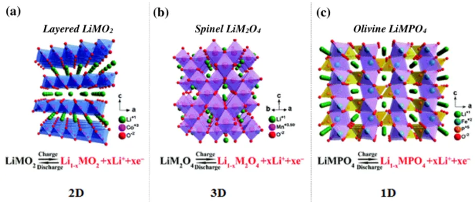
Cathode materials that fit these requirements are typically oxides of transition metals. At present time, the most common class of cathodes is represented by Li-insertion compounds, which can be further divided into three sub-classes (cfr. Figure 2.7) depending on ion diffusion pathways within the active material: two-dimensional layered oxides, three-dimensional spinel oxides, and uni-dimensional olivine compounds. Along these directions, the host structure is strongly bonded, and thus the intercalation reaction does not affect the host structure [43].
22 Electrochemical Storage Systems
Figure 2.7: Crystal structure, electrochemical reactions, and ionic pathways of Li-ion
trans-port mechanism of the principal cathode materials [54, 55].
Layered Oxides
Layered oxides have the generic formula LiMO2 whit M = Co, Mn, Ni or a com-bination of those, and have been employed as commercial cathodes for LIBs. They belong to the space group R3m where lithium and transition metals are located in the octahedral sites of alternating layers in an ABCABC stacking sequence (O3-type) and separated by layers of cubic close-packed oxygen atoms Fig.2.7(a) [56,57]. The most used layered materials in making LIBs cathodes are LiCoO2 and LiNiO2.
LiCoO2 was first commercialized by Sony Corporation in 1990 for the first commer-cialised model of LIB used it’s still commonly used for consumer devices nowadays [17]. The theoretical capacity of LiCoO2is 274 mAh g-1, corresponding to the de-intercalation of 1 mol of Li per mol of LiCoO2. Practically the empirical capacity of the material is reduced to 50% − 55% of the theoretical capacity (130 − 150mAh g-1) due to the irreversible structural modification of the material after the extraction of 0.5 mol of lithium from a hexagonal phase to a monoclinic. The low practical capacity, in conjunction with the high cost and high toxicity of cobalt, pushed the need to replace LiCoO2 with alternative cathode materials [56,58].
LiNiO2 is isostructural to LiCoO2, first reported by Dahn as cathode material [59], and is considered to be an alternative to cobalt-based layered electrodes; it is relatively cheaper and has higher energy density (15% by volume and 20% by weight). This material, however, presents difficulties during the synthesis in obtaining a stable and ideal R3m layered structure because nickel tends to the 2+ oxidation state and to migrate into Li+ sites [58].
To overcome these issues of LiCoO2 and LiNiO2, and to enhance the electrochemical performances and the structural stability of the materials, a layered cathode composed
2.2 Lithium-ion Batteries 23
by a combination of different metal oxides (Co, Ni and Mn oxides) has been proposed. These ternary oxides (reported by Ohzuku in 2001 [60]) are described by the general formula LiNiyMn1-x-yCoxO2, they are low-cost and present a low structural instability while the energy density is not much improved compared to LiCoO2 [61,62]. Another family of mixed layered oxides compounds are Li-rich cathode materials, with the general formula xLi2MnO3(1 −x)LiMO2 (0 < x < 1, M = Ni, Mn, Co, etc.). They show high capacity (over 300 mAh g-1) in the optimal potential range 2 − 4.8V, a low relative cost and no environmental issues; however, they suffer of a large initial irreversible capacity and a poor rate capability [62].
Spinel Oxides
Spinel oxide cathodes have been introduced in 1980 [63] as manganese spinel, as a cheaper and less-toxic alternative to cobalt layered materials. This manganese spinel (LiMn2O4) have a cubic close-packed structure (space group Fd3m), where manganese occupies the 16c sites and lithium the 8a sites, oxygen atoms are located at the 32e sites. Mn ions occupy 1/4 of the available octahedral sites, leaving the rest of the sites vacant and ready for a possible lithium insertion, the 8a and 16c sites form a 3D pathway for Li insertion and extraction [57,58] Fig.2.7(b). This material can intercalate one Li per formula unit at room temperature [43]; the theoretical capacity, in this case, is 148mAh g-1.
The main issue of these spinel cathodes is the capacity fade during charge and discharge cycles due to the dissolution of Mn3+ at the electrode surface according to the formula 2 Mn+3 −−→Mn4+
solid+ Mn 2+
solution with the consequent dissolution of Mn 2+ into the electrolyte. Another factor affecting the performances of manganese cathodes in LIBs is the Jahn-Teller induced distortion [64] and decomposition of the electrolyte at high-voltage regions [43,64].
Olivine Phosphates
LiFePO4 olivine was introduced by Radhi et al. [65] as cathode for rechargeable LIBs. Olivine structured transition metal phosphates LiMPO4 (M = Co, Fe, Mn) have attracted the attention of research due to the low-cost, nontoxic and environmentally friendly nature of these materials [43]. LiFePO4 operates at a very flat voltage of 3.4V versus Li+/Li, carrying a theoretical capacity of 170mAh g-1. The triphylite LiFePO
4 belongs to the olivine structured lithium ortho-phosphates in the space group Pnma; here the oxide ions form a hexagonal close packing arrangement; the iron ions form
24 Electrochemical Storage Systems
zigzag chains of octahedra in alternate basal planes linked by the tetrahedral phosphate groups (PO4) [43]. Each FeO4 octahedron share corners with 6 PO4 tetrahedra, and each of these tetrahedron shares, in turn, its corners with four FeO4, forming a 3-D framework. The lithium atoms occupy octahedral sites in the remaining basal planes Fig.2.7(c).
Besides LiFePO4, other olivine cathodes have been studied. In particular LiMnPO4
whit a working potential of 4.1V and also mixed compounds as Li(MnFe)PO4, Li(MnFeCo)PO4, and Li3V2(PO4)3. The latter one has a working potential of 3 − 4.8V versus Li
+/Li and an high theoretical capacity of 197mAh g-1, the highest among phosphates [66,67].
The main weaknesses of olivine-based cathodes are the low average potential and low electronic and ionic conductivity. The strategy to overcome these problems is focused on carbon coating and the reduction of particles to nano-metric size [46].
2.2.3
Electrolytes for LIBs
Electrolytes are widely used and indispensable in all electrochemical devices since they serve as the medium for the transfer of charges, in the form of ions, between a pair of electrodes. For this reason, they are key determinants of battery performance. The rate capability, stability, coulombic efficiency, temperature range and safety of any lithium-ion battery are affected by the composition of the electrolyte.
A suitable electrolyte should the following properties [68,69]:
• High ionic conductivity (σLi >10−4 S/cm) for minimizing the internal resistance
and at the same time a very low electronic conductivity (σe− >10−10 S/cm).
• Large and stable electrochemical window to ensure a wide operational voltage and avoid electrolyte degradation.
• Chemical compatibility with both the anode and cathode materials and all the other cell components.
• Low melting and high boiling point to enhance battery safety.
• Low cost, reliable safety characteristics, and environmental benignity.
Four types of electrolytes are used in Li-ion batteries: liquid electrolytes, gel electrolytes, polymer electrolytes and ceramic electrolytes. The most common are liquid electrolytes, solutions of a lithium salt in organic solvents, typically carbonates. The two main components of liquid electrolytes are the salt and the solvent. The
2.2 Lithium-ion Batteries 25
salt supplies the charge carriers needed to cycle Li-ions between anode and cathode. It must dissolve in the solvent and it should have high ion mobility to increase the conductivity [70]. Most commonly used salts and solvents are listed in Tables 2.4 and 2.5 respectively.
Table 2.4: Salts Used in Electrolytes for Li-ion Cells [17].
Common name Formula g/mol Comments
Lithium
hexafluorophosphate LiPF6 151.9 Most commonly used Lithium
etrafluoroborate LiBF4 93.74 Less hygroscopic than LiPF6 Lithium
perchlorate LiClO4 106.39 Less stable than LiPF6 Lithium
hexafluoroarsenate LiAsF6 195.85 Contains arsenic Lithium
triflate LiSO3CF3 156.01 Al corrosion at low voltage Lithium
bisperfluoroethane-sulfonimide(BETI)
LiN(SO2C2F5)2 387 Stable to water
The solvent needs to dissolve the salt in high amounts (i.e. have a high dielectric constant) and be fluid over a wide range of temperatures to allow for rapid ion transfer. At the same time, it should remain inert towards the electrodes and all other cell components. Other requirements include safety, economy and toxicity [71]. A wide variety of solvents, including carbonates, ethers and acetates, has been evaluated for non-aqueous electrolytes. The industry has now focused on the carbonates as they offer excellent stability, good safety properties and compatibility with electrode materi-als. Neat carbonate solvents typically have intrinsic solution conductivity less than 10−7 S/cm, dielectric constant > 3, and solvate lithium salts to high concentration [17].
From the first commercial Li-ion batteries, special attention was paid to ethylene carbonate (EC) [70], which has a dielectric constant (∼ 89). The unique position of EC as a lithium-ion battery electrolyte was established in 1990 when Dahn and co-workers reported the fundamental difference between EC and PC (propylene carbonate) in their effects on the reversibility of lithium-ion intercalation/deintercalation with graphitic anodes [41]. Despite the little difference in molecular structure between the two, EC was found to form an effective protective film (SEI) on a graphitic anode that prevented
26 Electrochemical Storage Systems
Table 2.5: Characteristics of main organic solvents [17].
Solvent EC ethylene-carbonate PC propylene-carbonate DMC dimethyl-carbonate DEC diethyl-carbonate DME dimethyl-ether EMC ethyl methyl-carbonate BP (◦C) 248 242 90 126 84 109 MP (◦C) 39 −48 4 −43 −58 −55 Density (g/ml) 1.41 1.21 1.07 0.97 0.87 1.0 Viscosity (cP ) 1.86 2.5 0.59 0.75 0.455 0.65 Dielectric constant 89.6 64.4 3.12 2.82 7.2 2.9 Mol. wt. 88.1 102.1 90.1 118.1 90.1 104.1
any sustained electrolyte decomposition on the anode, while this protection could not be realized with PC. Although ethylene carbonate as a single solvent is not suitable, because it is a solid at room temperature, it is used in mixtures containing linear alkyl carbonates such as dimethyl, diethyl, and ethyl-methyl carbonates (DMC, DEC, and EMC, respectively) [72]. Typical ready-to-use electrolytes contain 1 M LiPF6 salt dissolved in mixtures of EC, DEC, DMC or EMC. Chemical structures of most commonly used electrolyte solvents are shown in Figure 2.8.
Figure 2.8: Structures of main organic solvents used in Lithium-ion batteries [70].
2.3
Sodium-ion Batteries
Sodium is the fourth most abundant element on earth with a uniform distribution [73,74] with a virtually unlimited source in salt deposit and seawater. The abundance of
2.3 Sodium-ion Batteries 27
the resources and the much lower cost of sodium-containing precursors with respect to lithium precursors (135−165 $ per ton versus 5000 $ per ton [73]), and similar chemical proprieties provide a compelling alternative to Li-ion batteries in the development of Na-ion batteries (NIBs) technology, which in the recent years yield the research and industrial attention as large-scale energy storage system [17,73,75]. Fig. 2.9 shows the limited and uneven distribution of lithium supplies around the world, it is estimated that 89% of total Li income is controlled by four companies: Albemarle Corporation (USA), American FMC Lithium (USA), Sociedad Química y Minera de Chile (SQM, Chile), and Talison Lithium (Australia), which is owned by Albemarle Corporation (49%) and Tianqi Lithium Industries (51%) from China [76].
The battery components and the electrical storage mechanisms of NIBs and LIBs are basically identical except for their ion-carriers. For cathode material, the intercalation process of sodium is very similar to the one of lithium, making it possible to use similar compounds for both systems [73]. However there are obvious differences between the two systems: Na+ ions are larger than Li+ ions (1.02Å, versus 0.76Å), this affects the phase stability, transport and also the interphase formation [73,77]. Sodium is also heavier than lithium (23g/mol versus 6.9g/mol) and has a higher standard electrode potential (∼ 2.71V vs. SHE-standard hydrogen electrode, compared to ∼ 3.02V vs. SHE for lithium), thus NIBs will not prevail in terms of energy density. However, the weight of the ionic carriers is only a small fraction of the total mass of the battery components, furthermore, the capacity is primarily affected by the structural characteristics of the host structures that are employed as electrodes. Hence, in principle, there should not be large consequences in terms of energy density in the transition from LINs to NIBs [73]. Moreover, aluminium current collector can be employed in NIBs (while this is not possible in LIBs since aluminium undergoes an alloy reaction with lithium at potentials below 0.1V vs. Li/Li+) making it a cost-effective alternative to copper current collectors.
Also historically, the development of NIBs started parallel to that of LIBs. The first reversible electrochemical intercalation of sodium in TiS2 at room temperature was reported in 1980 [78], with a cathode that was later proposed as cathode material for the first rechargeable Li-ion battery. In the same year were reported the electrochemical proprieties of Na-containing layered oxides, NaxCoO2 by Braconnier [79]. However, the limitations in resources, research condition and apparatuses including electrolyte solution, binders, separators, and glove box proved to be insufficient for handling sodium metal at that time (sodium is more reactive in air than lithium), which resulted
28 Electrochemical Storage Systems
Figure 2.9: Global distribution of lithium supplies [76].
in difficulty in fairly observing potential of the electrode performance as batteries, led to a faster interest increasing into LIBs technology while NIBs research remained limited. Industrially, only a few Japanese and US companies developed, in the ’80s, a commercial version of NIBs in full cell configurations where sodium-lead alloy composite and P2-type NaxCoO2 were used respectively as a negative and a positive electrode [80, 81]. Only in recent years, the interest towards sodium-ion technology has been renewed to find a more cost-effective replacement for LIBs with a minimum sacrifice on performance and risk avoidance from export restrictions for lithium resources [73,82].
The main characteristics of Na compared to Li are summarized in Table 2.6 Table 2.6: Li and Na properties [55].
Li Na
Cationic radius (Å) 0.76 1.02 Atomic weight (g mol-1) 6.9 23 Potential vs SHE (V) ∼3.04 ∼ 2.7 Melting point (°C) 180.5 97.7 Price, carbonates ($/ton) 5000 150 Capacity metal (mAh g-1) 3829 1165
A description of the most relevant classes of active materials and electrolytes under investigation for NIBs is given in the next sections, comparing them with LIBs relative counterparts, while a simplified schematics of a Na-ion cell with all the commonly used materials is presented in Figure 2.10.
2.3 Sodium-ion Batteries 29
Figure 2.10: Schematics of a Na-ion battery and the principal classes of materials in the
components [73].
2.3.1
Anode Materials
The main challenge in NIBs technology is mainly represented in finding a suitable replacement for the anode material for Na-ions storage. Similarly to LIBs, metallic Na cannot be used because of the dendritic growth upon cycling which leads to short circuits and safety hazards, also the low melting temperature of metallic sodium increases the safety risks and makes it not suitable in commercial uses [76,83]. Similarly to LIBs, negative electrode materials for NIBs can be classified based on their reaction mechanism during the sodiation/de-sodiation process and divided in insertion, alloying and conversion anodes. An overview of these materials is shown in Figure 2.11 [55,73].
30 Electrochemical Storage Systems
Insertion Anodes
• Carbonaceous materials
As seen in a previous section (2.2.1), carbon-based materials (graphite in particular) are the most common choice in LIBs manufacturing since Li rapidly forms intercalated compounds with it in which lithium ions are located at the graphene inter-layer until C:Li ratio reaches 6 : 1 (LiC6). However, in NIBs, Na
+ insertion into graphite is significantly impeded since it is electrochemically less performing and furthermore causes the degradation of electrolyte and/or electrode materials, especially with common carbonate esters electrolyte solvents [84, 85]. Moreover the formation of NaC6 and NaC8 is unfavourable because of the thermodynamic instability of binary Na-Graphitic Intercalation Compounds (GICs) [73]. Early first-principles calculations indicated that it is hard for Na to form the intercalated graphite compounds compared to other alkali metals [86,87]. Na-ion insertion into graphite can be facilitated by the use of solvated Na-ion co-intercalation reaction, by the use of diglyme (diethylene glycol dimethyl ether) electrolyte solvent [88].
On the other hand, disordered carbons showed better performances in intercalating Na+, with a higher reversible specific capacity. First report of sodium-ions intercalating in soft carbons prepared by pyrolysis of petroleum cokes was in 1993 by Doeff et
al. [84]; while in 2000, Steven and Dahn obtained a specific capacity of 300 mAh g−1
for sodium-ion intercalation in hard carbons prepared by carbonization of glucose [89]. • Titanium-based oxides
Similarly to LIBs, titanium-based active materials have been studied and exten-sively investigated as negative electrodes for NIBs, because of the relatively low redox potentials of Ti3+/4+. Several Ti-based sodium compounds demonstrated to reversibly intercalate Na ions. For example layered NaTiO2 and Na2Ti3O7 [86]. Also intercala-tion into spinel-like structures is possible, reversible intercalaintercala-tion of Na+ into spinel Li4Ti5O12 has been reported [90], with a delivered reversible capacity of 145 mAh g
−1 and a potential of 1 V. Ionic insertion mechanisms between LIBs and NIBs differ in spinel material. While Li+ insertion occurs via a 2-phases mechanism, Na+ insertion happens in a three-phases process; this mainly because of the larger ionic radius of sodium [73].
Another class of interest for NIBs anodes using an insertion mechanism is represented by sodium titanates, in particular Na2Ti3O7 because it can reversibly uptake 2 Na
2.3 Sodium-ion Batteries 31
ions per formula unit through a two-phase reaction, giving a final theoretical capacity of 177 mAh g−1, with a low operating potential plateau of 0.3 V vs Na/Na+ [91].
Alloying Anodes
Similarly to lithium, also sodium can form binary compounds with pure metals and semi-metals of elements in group 14 and 15 in the periodic table (M+nNa++ne–−−Na
nM). Those alloys are very attractive for the construction of NIBs due to their high theoretical capacities. For example, there are reports of alloying reactions of Pb to form Na3.75Pb [92]. The most encouraging candidates as alloying metals with sodium are Sn and Sb. Sn shows an high theoretical capacity of 847 mAh g−1 while Sb delivers a theoretical specific capacity of 660 mAh g−1, based on full sodiation state of Na
3Sb.
The main withdraw of alloying sodium comes from the large ionic radius that inevitably causes more detrimental volume expansions upon (de)sodiations, causing irreversible structural modifications and finally the pulverization of the electrode active material, with the related capacity loss (a comparison of volumetric expansion between carbons anodes for LIBs and NIBs is provided in Figure 2.12). For this reason, the current research in this field is mainly focused on controlling the effect of volume changes with similar strategies used for lithium counterparts [93].
Whereas silicon has been considered the most promising anode in Li-ion batteries thanks to its electrochemical performances, it is not as promising in Na-ion batteries because it can only uptake one sodium ion per formula unit and exhibits poor Na diffusion kinetics [94]. An improvement of silicon electrochemical performances has been obtained with amorphous Si due to a more favourable binding reaction with Na [73].
The electrochemical alloying of Sb-Na was also reported [95] in Sb2O4 thin films which alloys sodium after conversion, showing a total theoretical capacity of 1227 mAh g−1 since it can store 14 Na ions per formula unit of Sb
2O4.
Conversion Anodes
Conversion anodes for NIBs have been intensively tested, the main representatives of this class of materials are: transition metal oxides, transition metal sulphide and transition metal phosphide.
Conversion reactions have been studied also in spinel-like materials as NiCo2O4 [97] where a reversible reaction was described between the metal oxide and sodium, where Co and Ni metallized in a matrix of Na2O after full sodiation. Also other types of
32 Electrochemical Storage Systems
Figure 2.12: Universal expansion curves for Li and Na alloys [96]. Voltage of positive
electrode was assumed to be 3.75 V to calculate the energy density.
transition metal oxides were proposed as electrodes in NIBs, such as iron oxides (Fe3O4 and Fe2O3), cobalt oxide Co3O4 and copper oxide CuO, molybdenum oxide (MoO2), nickel oxide (NiO) and finally manganese oxide (Mn3O4).
These conversion materials gathered attention due to their high theoretical specific capacities but they suffer from poor cycling stability and large hysteresis. Therefore the main goal for improvement is focused on nanotechnology and carbon coating strategies [73].
2.3.2
Cathode Materials
Most of cathode materials used for NIBs are based on intercalation reactions, which involves sodium ion insertion into interstitial spaces of the material. Since intercalation chemistry of sodium is very similar to lithium, the same compounds used in LIBs have been tested also for NIBs. Therefore a large class of materials have been proposed as possible positive electrodes for NIBs, we can divide those into layered oxides, polyanionic compounds, Prussian blue and organic compounds. All those are characterized by minimal structural changes during intercalation, but due to the ionic dimension, these material are always subjected to continuous structural evolution during sodiation of the host structure [73]. Figure 2.13 gives an overview of the large class of NIBs positive electrode materials. Here we will focus only on layered oxides.
![Figure 2.15: Sketch of the SEI evolution in zinc-ferrite anodes [112].](https://thumb-eu.123doks.com/thumbv2/123dokorg/5386697.56714/47.892.219.704.269.491/figure-sketch-sei-evolution-zinc-ferrite-anodes.webp)
![Figure 4.1: Schematic drawing of the carbon coating process of ZnFe 2 O 4 nanoparticles, resulting in an amorphous carbon shell (ZnFe 2 O 4 −C) [49].](https://thumb-eu.123doks.com/thumbv2/123dokorg/5386697.56714/81.892.247.669.155.370/figure-schematic-drawing-coating-process-nanoparticles-resulting-amorphous.webp)
![Figure 4.2: a) XRD pattern of ZFO-C [55] and (b) SEM image of carbon-coated zinc ferrite](https://thumb-eu.123doks.com/thumbv2/123dokorg/5386697.56714/83.892.184.735.385.587/figure-xrd-pattern-zfo-image-carbon-coated-ferrite.webp)
