P
OLITECNICOD
IM
ILANOF
ACOLTA DI`
I
NGEGNERIAI
NDUSTRIALEC
ORSO DIL
AUREAS
PECIALISTICA INI
NGEGNERIAS
PAZIALEBOREAS
An air-launched light satellite launcher design
Relatore: Prof. Mich`ele Lavagna Co-relatore: Ing. Floriano Venditti
Tesi di laurea magistrale di Massimo Vetrisano, 711985
As for the future, your task is not to foresee it, but to enable it. A. de Saint-Exupery
Contents
Acknowledgement XVII
Sommario XVIII
Abstract XX
1 Introduction 1
1.1 Small Satellite and Market . . . 1
1.2 Small-Medium Launcher . . . 4
1.3 Air launched vehicles . . . 11
1.3.1 Launch strategies . . . 11 1.3.2 Captive on top . . . 11 1.3.3 Captive on bottom . . . 16 1.3.4 Towed . . . 18 1.3.5 Aerial Refueled . . . 19 1.3.6 Internally carried . . . 21 1.4 Considerations . . . 23 1.4.1 Work organization . . . 25 2 General configuration 27 2.1 System presentation . . . 27 2.1.1 Safety concerns . . . 29
CONTENTS
2.2.1 Z9 solid engine . . . 32
2.2.2 HM-7B cryogenic engine . . . 33
2.2.3 Bipropellant apogee engine,Astrium S400-12 . . . 34
2.2.4 Interstage and fairing . . . 36
2.2.5 Considerations . . . 37
2.3 Mass budget and sizing . . . 37
2.3.1 Cryogenic propellant system . . . 38
2.3.2 Second stage mass budget . . . 43
2.3.3 Third stage mass budget . . . 44
2.3.4 Interstage and fairing design . . . 48
2.4 Complete rocket configuration . . . 49
3 Atmospheric configuration design 52 3.1 Launcher and Aero-Module . . . 53
3.2 Carrier Aircraft . . . 59
3.2.1 Selection of aircraft types . . . 59
3.2.2 Modification to the carrier aircraft . . . 61
4 Launcher dynamics: the release and ascent manoeuvres models 67 4.1 Launcher dynamics models . . . 67
4.1.1 The release manoeuvre dynamics model . . . 68
4.1.2 The ascent phase dynamics model . . . 69
4.2 Atmospheric model . . . 71
4.3 Aero-Module actions definition . . . 73
4.4 Launcher actions . . . 74
4.4.1 Gravitational force model . . . 75
4.4.2 Aerodynamic drag model . . . 75
4.4.3 Thrust model . . . 75
4.5 Control law synthesis . . . 76 IV
CONTENTS
4.5.1 The first stage phase . . . 76
4.5.2 The second stage phase . . . 79
4.5.3 The third stage phase . . . 80
4.6 Release manoeuvre requirements . . . 82
4.7 Release Manoeuvres . . . 83
5 Guidance and control simulation and results 86 5.1 Release manoeuvre results . . . 86
5.1.1 Separation during horizontal flight . . . 86
5.1.2 Inclined separation manoeuvre . . . 91
5.2 Considerations . . . 95
5.3 Power ascent simulation . . . 97
5.4 Heat fluxes on fairing . . . 105
5.5 Flight trajectory optimization . . . 106
5.6 Performances . . . 108
6 Design of Kerosene-LOx launcher 112 6.1 Falcon I architecture . . . 112
6.2 Parametric design for liquid engine rocket . . . 114
6.3 Parametric design for the structures . . . 118
6.4 Optimization procedure . . . 119
6.4.1 Discussion . . . 120
6.4.2 Performance . . . 123
6.4.3 Direct insertion . . . 125
7 Refined model for performances evaluation 127 7.1 Rocket Attitude . . . 127
7.2 Rocket controller . . . 130
7.3 Results . . . 131
CONTENTS 8 Conclusions 134 8.1 Innovative aspects . . . 134 8.2 Future developments . . . 135 References 139 A Software Validation 140 A.1 Comparison with Fortran . . . 140
A.2 Pegasus characteristics . . . 142
A.3 Test case . . . 144
A.4 Consideration . . . 146
B Genetic Algorithms 147 B.1 Optimization based on genetic algorithms . . . 148
B.1.1 Components of the genetic algorithm . . . 149
List of Figures
1.1 Distribution of world small satellite launched (1996-2006) and to be launched (1997-2016)
by mass category . . . 2
1.2 Distribution of small satellite launched (1996-2006) and to be launched (1997-2016) by mass and altitude. . . 3
1.3 Distribution of small satellite launched (1996-2006) and to be launched (1997-2016) by mass and inclinations . . . 3
1.4 Scout rocket . . . 4
1.5 Volna launch from submarine . . . 5
1.6 Dnepr launcher . . . 7
1.7 Vega launcher. . . 8
1.8 Rockot launcher. . . 9
1.9 Leduc/Linguedoc and Space Shuttle Approach and Landing Test . . . 12
1.10 Spiral 50-50 credited c Dan Roam . . . 12
1.11 Saenger II credited c Mark Lindroos . . . 13
1.12 Interim HOTOL credited c British Aerospace . . . 13
1.13 MAKS credited c NPO Molniya . . . 14
1.14 Boeing AirLaunch credited c Boeing. . . 15
1.15 Pegasus XL . . . 16
1.16 Yakovlev HAAL . . . 17
1.17 CNES concepts . . . 18
LIST OF FIGURES
1.19 Pathfinder credited c Pioneer Rocketplane . . . 20
1.20 Drop of Minuteman missile C-5A in 1974. . . 22
1.21 Darpa’s Falcon rocket . . . 22
1.22 Velocity loss for a Sun-synchronous 200 km circular orbit . . . 25
2.1 General configuration . . . 28
2.2 Flight and launch phases . . . 28
2.3 Reference flight profile . . . 29
2.4 Possible launch sites . . . 30
2.5 Direct Insertion: first and second stage fall-out . . . 31
2.6 Z9 characteristics . . . 32
2.7 Z9 assumed thrust profile . . . 33
2.8 HM-7B engine characteristics . . . 34
2.9 S400-12 engine characteristics . . . 35
2.10 Third stage: general layout . . . 36
2.11 Payload envelope ( example for Pegasus launcher) . . . 37
2.12 Second stage tanks layout . . . 40
2.13 Pressure regulated vs blowdown system . . . 42
2.14 Third stage: installation on the launcher . . . 45
2.15 Propellant for de-orbiting . . . 47
2.16 Dimension for CoG estimation. . . 50
3.1 The Aero-Module . . . 52
3.2 Top view of the launcher with Aero-Module . . . 56
3.3 Centers of pressure position . . . 57
3.4 ESA/CNES A300 Zero-g and Airbus A330-200 . . . 60
3.5 Accommodation of the Launcher on an Airbus A330-200 . . . 62
3.6 Position of connections to the A/C and alternative position at rear side . . . 63
3.7 Beluga aircraft with the additional fins . . . 64 VIII
LIST OF FIGURES
3.8 Telemetry reception system . . . 65
4.1 Initial condition . . . 70
4.2 Aerodynamic system . . . 74
4.3 Speed and position misalignment . . . 77
4.4 Third stage conceptual goals. . . 79
4.5 Third stage conceptual goals. . . 81
5.1 A/C and launcher position . . . 87
5.2 A/C and launcher relative module distance . . . 88
5.3 Horizontal separation and launcher speed components . . . 88
5.4 Normal loads on launcher . . . 89
5.5 Flight path angle . . . 90
5.6 Angle of attack . . . 90
5.7 Inclined release: A/C and launcher position . . . 92
5.8 Inclined release: A/C and launcher relative module distance . . . 92
5.9 Inclined release: horizontal separation and launcher speed components . . . 93
5.10 Inclined release: normal loads on launcher . . . 94
5.11 Inclined release: flight path angle . . . 94
5.12 Inclined release: angle of attack . . . 95
5.13 Attitude consideration . . . 96
5.14 Flight path angle relative to the orbital plane . . . 96
5.15 SSO at 600 km launch: altitude vs time . . . 98
5.16 SSO at 600 km launch: altitude vs time - detail . . . 99
5.17 SSO at 600 km launch: trajectory - 3D detail . . . 99
5.18 SO at 600 km launch: velocity vs time . . . 100
5.19 SSO at 600 km launch: acceleration vs time . . . 100
5.20 SSO at 600 km launch: thrust vs time. . . 101
LIST OF FIGURES
5.22 SSO at 600 km launch: angle of attack vs time . . . 102
5.23 SSO at 600 km launch: plane flight path angle vs time. . . 104
5.24 SO at 600 km launch: dynamic pressure vs time . . . 104
5.25 Heat fluxes on fairing . . . 106
5.26 Control laws . . . 107
5.27 Sensitivity on mass . . . 108
5.28 Sensitivity on initial in plane speed . . . 110
5.29 Sensitivity on fairing separation time. . . 110
6.1 Falcon 1 . . . 114
6.2 Nozzle definitions. . . 117
6.3 Mass breakdown . . . 122
6.4 Performance comparison in nominal condition . . . 123
6.5 LOx-Kerosene: sensitivity analysis . . . 124
6.6 Two burns insertion and direct insertion for kerosene-LOx launcher . . . 125
6.7 Two burns insertion and direct insertion for different Falcon launcher . . . 126
7.1 Rocket principal axis . . . 128
7.2 Attitude reference frames . . . 129
7.3 6 DoF Assembled launcher: Altitude and θr . . . 132
7.4 6 DoF Assembled launcher: parameters and thrust wrt plane . . . 132
7.5 Angle between xrprojection on zp− ypplane and orbital plane . . . 133
A.1 Fortran simulation results: Altitude . . . 141
A.2 Fortran simulation results: speed and acceleration . . . 141
A.3 Fortran simulation results: thrust and out of plane velocity . . . 142
A.4 Fortran simulation results: flight path angle and angle of attack . . . 142
A.5 Pegasus XL Performance Capability . . . 143
A.6 Pegasus’s simulation results for 230 kg on 741 km circular orbit: altitude and θr . . . 145
LIST OF FIGURES
A.7 Pegasus’s simulation results for 230 kg on 741 km circular orbit: acceleration and AoA . . 146 B.1 Flow chart of a genetic algorithm . . . 150
List of Tables
1.1 Scout-G launcher . . . 5 1.2 Dnepr launcher . . . 7 1.3 Vega data . . . 8 1.4 Rockot launcher. . . 9 1.5 Kosmos-3M launcher . . . 10 1.6 PSLV operational launcher . . . 101.7 Pegasus XL launcher data . . . 17
1.8 Air-launch method comparisons . . . 24
2.1 Second stage:parameters for sizing. . . 38
2.2 Second stage:propellant sizing . . . 39
2.3 Propellant used for tank sizing. . . 39
2.4 Second stage: tanks parameters . . . 39
2.5 Second stage:tanks parameters. . . 40
2.6 Material physical characteristics . . . 41
2.7 Constant Ktypefor liquid propellant . . . 41
2.8 Mass tanks . . . 41
2.9 Second stage: pressurant gas sizing . . . 43
2.10 Second stage mass budget . . . 44
2.11 Third stage: maximum propellant required for 2000 km SSO . . . 46
2.12 Third stage: tanks sizing and mass estimation . . . 46 XII
LIST OF TABLES
2.13 Third stage: mass budget . . . 48
2.14 Interstage mass estimation. . . 49
2.15 Fairing mass estimation . . . 49
2.16 Elements mass and CoG with complete mass budget . . . 50
3.1 The Aero-Module: wing characteristics. . . 55
3.2 The Aero-Module: stabilizer characteristics. . . 56
3.3 The Aero-Module: trimming and centers of pressure . . . 56
3.4 Assumptions for trimming . . . 57
3.5 Aero-Module mass breakdown . . . 58
3.6 Characteristics and performances of candidate carrier aircrafts . . . 61
4.1 Temperature model coefficients . . . 72
4.2 Control coefficients for out of plane control. . . 79
4.3 Separation manoeuvre sequencing . . . 84
4.4 Aerodynamic characteristics for the Aero-Module . . . 85
4.5 Aerodynamic characteristics for Airbus A330. . . 85
5.1 Third stage 570kg: initial condition . . . 97
5.2 Power ascent timeline . . . 98
5.3 Prandtl number and specific heat coefficient . . . 105
5.4 Control laws: performances comparison . . . 107
5.5 Sensitivity analysis on stage mass . . . 109
5.6 Sensitivity analysis on initial vertical sped and fairing separation . . . 111
6.1 Falcon 1: features . . . 113
6.2 Useful data for engine sizing . . . 115
6.3 Optimization kerosene/LOx launcher . . . 120
6.4 Optimization kerosene/LOx launcher . . . 120
LIST OF TABLES
6.6 LOX-Kerosene launcher: engines characteristics . . . 121
6.7 LOx-Kerosene:Elements mass and CoG with complete mass budget . . . 121
6.8 Stage masses . . . 122
6.9 Comparison between assembled and kerosene launcher . . . 123
6.10 The Aero-Module for LOx-kerosene launcher: trimming and centers of pressure . . . 124
6.11 Sensitivity anlaysis on kerosen launcher mass . . . 125
6.12 Comparison between direct and two burn insertion. . . 126
7.1 First stage inertiae . . . 129
A.1 Pegasus’s main characteristics . . . 143
A.2 Pegasus’s typical attitude and guidance modes sequence . . . 144
A.3 Pegasus’s simulation parameters for 230 kg on 741 km circular orbit . . . 145
Acronyms
A/C AirCraftALV Air Launched Vehicle
AoA Angle of attack
CoG Centre of Gravity
CNES Centre National d’ ´Etudes Spatiales CPM Conventional Payload Module
DLR Deutschen Zentrums f ¨ur Luft-und Raumfahrt
dof degree of freedom
ESA European Space Agency
FPA Flight path angle
NASA National Aeronautics and Space Administration IMU Inertial Measurement Unit
ICBM Inter Continental Ballistic Missile LEO Low Earth Orbit
LH2 Liquid Hydrogen
LOx Liquid Oxygen
MRTT Multi-Role Tanker Transport
MEOPMaximu Expected Operating Pressure
SL Sea Level
SLV Small Launch Vehicle
SMV Space Maneuver Vehicle
SSO Sun-Synchronous Orbit
TC TeleCommand
TM TeleMetry
TPS Thermal Protection System
TVC Thrust Vector Control
UDMH Unsymmetrical dimethyl-hydrazine VAC Vacuum
wrt with respect to
Acknowledgement
To my father
I would like to thank the Carlo Gavazzi Space S.p.A. where I had the opportunity to carry out this thesis.
A special mention goes to Mr. Floriano Venditti, who encouraged my work with his critical sense and who gave me many opportunities to exchange ideas. I would like to thank the guys of the Space Vehicle and Exploration Team, Emanuele, Igor and Filippo, that not only provided to me a clearer idea of what the industrial world is, but with who I also had many amazing and funny moments.
At the same time, a big thank goes, of course, also to all my friends and colleagues of the Space Engineering degree and of the Politecnico di Milano in general, with who I shared many hard and nice periods.
I would like to express my gratitude to the professors of Politecnico di Milano, that offered to me many opportunities to improve my education and that during these years have been with me throughout all the difficulties helping me to achieve this goal.
A heartfelt thank goes to my family and to all my true friends that always supported me. A final and special thank goes to my girlfriend Valentina, that pushed me to do always my best in any situation.
Sommario
Il presente lavoro di tesi si inserisce nel contesto del Future Launcher Preparatory Pro-gramme (FLPP) dell’Agenzia Spaziale Europea (ESA); il programma nasce dal desiderio di ridurre i costi di lancio per sistemi spaziali di dimensioni contenute. Un aspetto chiave da analizzare in questo ambito riguarda la gestione razionale delle risorse e delle infrastrutture connesse alla totalit´a della fase di lancio: in particolare, la sostituzione del lancio del vettore dal suolo con il lancio da aereo permetterebbe di usufruire di un semplice aeroporto militare, di evitare i vincoli di carattere politico/nazionale, di semplificare le norme di sicurezza e di ridurre i requisiti sul sito stesso di lancio. Inoltre tale approccio consente una certa flessibilit`a per i satelliti di piccole dimensioni. Oggigiorno il progetto di tali satelliti deve tenere in considerazione che essi vengono lanciati come carico pagante secondario, il che implica la ricerca di un compromesso tra l’orbita disponibile e quella desiderata. Ci `o causa spesso ritardi con un conseguente aumento dei costi. Il lancio aereo offre a questa classe di satelliti la possibilit´a di essere posizionati sull’orbita operativa desiderata senza ulteriori manovre ad alto costo quali i cambi di piano orbitale.
Il presente lavoro discute i risultati ottenuti dallo studio di fattibilit`a svolto per un lanciatore sganciato da aereo. Si ´e scelto di mantenere un approccio multidisciplinare nello studio che coinvolgesse gli aspetti di configurazione, propulsivi e di controllo. Si ´e effettuato uno studio dettagliato della dinamica del veicolo, dagli effetti legati alla strategia di sgancio fino all’immissione nell’orbita operativa. Si ´e prestata particolare attenzione all’impiego di componentistica gi´a presente sul mercato o in attuale sviluppo per piccoli lanciatori, includendo tra i criteri di valutazione non solo le tipiche prestazioni di lanciatori (massa/quota) ma anche la modularit´a progettuale cosi da consentire l’impiego di differenti soluzioni propulsive. Lo studio svolto ha permesso di evidenziare e quantificare gli aspetti critici che maggiormente impattano sulla massa di carico pagante.
Il primo capitolo introduce le necessit`a di natura tecnica ed economica alla base di un XVIII
lanciatore leggero di tipo air-launched ed espone lo stato dell’arte nell’ambito di questa tipologia di lanciatori.
Il secondo e terzo capitolo espongono la configurazione iniziale e generale del lanciatore sviluppato a partire dall’obiettivo di costruire un assembly di componenti messi a disposizione dall’industria aerospaziale europea. Quanto riportato nel terzo capitolo ´e, inoltre, estendibile al lanciatore propulso da motori a kerosene e ossigeno, sviluppato nel sesto capitolo.
Il quarto capitolo analizza la manovra di rilascio del complesso, costituito dal missile e dal modulo alare, dall’aereo che ha il compito di portarlo nella zona di lancio e di garantire appropriate condizioni iniziali di volo.
Il quinto capitolo illustra la dinamica del vettore dopo il rilascio dall’aereo ed il distacco dalle ali, e riporta le prestazioni in termine di massa del carico pagante posta ad una certa quota su orbita circolare eliosincrona.
Il sesto capitolo discute la progettazione di un lanciatore con sistema propulsivo a base di kerosene e ossigeno liquido, in grado di garantire analoghe prestazioni. La motivazione di tale studio risiede nei possibili rischi legati alla presenza di sistemi propulsivi eterogenei, i quali caratterizzano il sistema assemblato.
Nel settimo capitolo si riporta un modello a sei gradi di libert`a del lanciatore e discute le problematiche dovute alla perdite di prestazioni legate essenzialmente alla fase di distacco del modulo alare nella fase precedente all’ignizione del primo stadio.
Parole chiave
ALV (Air Launched Vehicle); Controllo di vettore spaziale; Dinamica del razzo; Pro-gettazione di traiettorie di lancio; Manovra di separazione in volo; Sistema propulsivo liquido; Progetto di missile.
Abstract
The current thesis work can be considered as part of the Future Launcher Preparatory Programme (FLPP) of the European Space Agency (ESA); this programme arises from the wish to reduce the launch costs for small space systems. A key point to be analysed in such a field is relevant to a clever management of the resources and of the infrastructures linked to each launch phase: in particular, the substitution of a ground-based launch with a air-to-air launch that would allow to exploit a simple military airport, to avoid political and national issues, to simplify safety procedures and to reduce requirements on the launch base. Moreover, this approach increase also the flexibility of the small satellites. In fact, nowadays, the design of such satellites has to take into account the fact that they are launched as secondary payload, which implies the need to accept a compromise between the achievable orbit and the preferred one. This often causes delays and, then, an increase of the launch costs. An air-to-air launch from an airplane would offer to this class of satellites the possibility to be placed on the preferred operative orbit without any additional manoeuvre requiring a higher propulsive cost (e.g. plane changes).
The current work also discuss the results obtained during the feasibility study for a launcher released by a plane. A multidisciplinary approach has been selected, allowing to consider also the configuration, propulsion and control aspects. A detailed analysis of the launcher dynamics has been performed, taking into account all the phases of the mission, from the release strategies up to the insertion in the final orbit. Special attention has been focused on the use of off-the-shelf components and in the components that are currently under development for the small launchers, including among the evaluation criteria not only the performance of the launchers (e.g. mass, achieved orbit), but also the flexibility of their propulsive systems to face different missions. This study has also allowed to highlight and quantify the critical aspects that mainly impact the payload mass.
Chapter One introduces the technical and economical requirements that pushed towards the need of such a light launcher, type air-to-air, and provides the current status of the art
of this class of launchers.
Chapters Two and Three describe the initial general configuration of the developed launcher taking into account the objective to build an assembly of some components already available in the European aerospace industry market. What is reported in Chapter Three is also applicable to a launcher propelled with kerosene/oxygen engines (see also Chapter Six).
Chapter Four analyses the release manoeuvre of the whole system, that includes the missile, the wings module and the plane that has the goal to bring it up to the loading zone and to guarantee suitable initial flight conditions.
Chapter Five shows the launcher dynamics after the release from the plane and the sepa-ration of the vehicle from the plane wings surface. It provides also the performance of the launcher in terms of payload mass with respect the final height of the eliosynchronous circular orbit.
Chapter Six describes the design of a launcher with a propulsion system fueled with kerosene and liquid oxygen, and able to guarantee similar performances. The motivation of such a design is due to the possible risks that could be linked to the presence of different heterogeneous propulsion systems, which characterize the final assembly.
Finally, the last chapter, Chapter Seven, reports a six.degrees of freedom model of the launcher, and discusses about the problematics mainly due to the release mechanisms that could not provide the expected performances during the separation phase of the wings module.
Key words
ALV (Air Launched Vehicle); Missile control; Rocket dynamic; Ascent trajectory opti-mization; Separation flight manoeuvre; Liquid propulsion system; Rocket design.
Chapter 1
Introduction
This thesis focuses on the multidisciplinary study to assess the feasibility for an air-launched launcher for small satellites. The thesis was conceived and developed within the Space Vehicles and Exploration Department at Carlo Gavazzi Space Spa, Milan, under the supervision of the Engineer Floriano Venditti, between April 2009 and March 2010. The name of the studied system, Boreas, after the name of the Roman God of Northern winds, stands for Bipropellant Operational Responsive European Air-launched System and has been chosen because explanatory of the its main features.
In fact, the most important design driver has been to identify a flexible and responsive launcher subjected to a limited number of constraints, requiring short forewarnings before to be launched, and exploiting the european launch areas that are mainly localized over the Atlantic Ocean.
The current chapter highlights motivations for air-launched systems offering their current state of development too.
1.1
Small Satellite and Market
The interest of a dedicated launch system follows the recent proliferation of micro-satellite platforms and the increasing success of the associated applications. In particular, it is due to:
• numerous successful technology demonstration experiences based on micro-satellites, for Science or Defense applications with gradual increase in instrument perfor-mance,
1.1. SMALL SATELLITE AND MARKET
• constant improvements of quality versus cost,
• rebirth of interest for constellations ( e.g. Rapid eyes, Orbcomm2, numerous project worldwide etc.) and formation flying,
• increasing number of operational applications becoming accessible to small satel-lites: communications, intelligence gathering, early warning, space surveillance, different types of observation, etc.,
• evidence of the vulnerability of the large space systems, i.e. their complexity, high launch and recurrent costs due to long period of development, the difficulty of tailored mission for small satellites,
• increasing interest for the Responsive Space approach in the U.S. and other countries (China, etc.); this approach prefers small size systems in order to reduce global costs and delays, thanks also to the reduced size of the required facilities and space-ports, to limit the safety launch concerns, and to facilitate the implementation of new technologies
The current market for small satellites (less than 500 kg) is more active in the micro-satellites range (40-150 kg, refer to [1]). Over the last few years there has been a strong increase in demand for launching of that class of satellites, for which more and more platforms are available1.
Figure 1.1: Distribution of world small satellite launched (1996-2006) and to be launched (1997-2016) by mass category
1figures reported in this paragraph have been elaborated in the Euroconsult Market Study(see [1]) for small
1.1. SMALL SATELLITE AND MARKET
This increase in number might also be accompanied by an increase in satellite masses (increase from 150 to 200 kg, or even more) in order to optimize mission yields.
Figure 1.2: Distribution of small satellite launched (1996-2006) and to be launched (1997-2016) by mass and altitude
As it can be seen in figure 1.2, most of the satellites to be launched in LEO have a mass that is less than 500kg, that is the target payload mass for the launcher studied in this thesis.
Satellites, which will be launched in the next years, have as preferred injection orbit the Sun-synchronous orbit (SSO):
Figure 1.3: Distribution of small satellite launched (1996-2006) and to be launched (1997-2016) by mass and inclinations
1.2. SMALL-MEDIUM LAUNCHER
For this reason the study of launch vehicles targeted to small satellites into Sun-synchronous orbit is definitely needed. The launch of small satellites can be accomplished via two different alternative launch systems, that are the traditional one performed from a ground facility by using a small-medium launcher, or the one exploiting the use of air launch vehicles. The state of the art according to the two aforementioned classes is briefly presented in the following, to better highlight their limitations and possible rooms for new solutions.
1.2
Small-Medium Launcher
In the past years Small launchers derived from military ballistic nuclear rockets. The U.S. Scout family rockets were launch vehicles designed to place small satellites into orbit around the Earth and were operative in the period 1961-1994.
• Scout
(a) (b)
Figure 1.4: Scout rocket
The Scout four-stages rocket was the first (and for a long time, the only) orbital launch vehicle to be entirely composed of solid fuel stages. The first successful orbital launch of a Scout, on February 16, 1961, delivered the Explorer 9 in its final
1.2. SMALL-MEDIUM LAUNCHER
orbit the Explorer 9, a 7kg satellite used for performing studies about the density of the atmosphere. The main dedicated launch complex was the Wallops Flight Facility. Scout capability grew dramatically over the years. Originally able to place a 59-kilogram payload in a nominal 552-kilometer circular orbit, Scout performance was improved, increasing its capability up to put a 208-kilogram payload into the same orbit. Thanks to this launcher, Italy became the third space country putting on orbit its first satellite, San Marco 1, in 1964. Italian was also the heaviest satellite it had ever placed in orbit which weighed more than 270 kilograms. Scout increased its load-carrying capability up of the 350 percent with respect its original capability with only a little increase in size of its stages. The mean cost per launch was about 10 million U.S. dollars.
1st Stage Algol 2ndStage Castor 3rdStage Antares 4thStage Altair
Gross mass [kg] 14320 4424 1637 301
Propulsion type Solid Solid Solid Solid
Thrust [kN] 622.8 266.9 80.0 26.7
Burning time [s] 82 41 4x 34
Table 1.1:Scout-G launcher
• Volna
Ballistic rockets play a predominant role as favourite light launcher vector . This is due essentially to the great availability of this kind of missile, mainly from former soviet countries.
Figure 1.5: Volna launch from submarine
1.2. SMALL-MEDIUM LAUNCHER
The Ukrainian space launch vehicle Volna , is a converted submarine-launched ballistic missile used for launching artificial satellites into orbit.
The main advantage of this kind of launch method stands in the fact that it allows to reduce safety concerns linked to the ground launch.
The Volna is a 3 stage launch vehicle that uses hypergolic liquid propellant.
The warhead section is used for the payloads that can be either put into orbit with the help of an additional boost engine or travel along a sub-orbital trajectory to be recovered at the landing site. Volna can be launched from Delta III class submarine or from land based facilities.The Volna missile weighs 35 tons, and has a length of 14.2 metres and a range of 8000 kilometres.
Because of its mobile launch platform the Volna launch vehicle can reach a large number of different inclinations and could increase its performance to low Earth orbit by launching from equatorial sites.
All flights to date have taken place from the Barents Sea. From this site the Volna can lift 100kg into a 400km high orbit with an inclination of 79 degrees. The warhead section can accommodate a payload of up to 1.3 m3.
For sub-orbital missions the payload can be either a recoverable vehicle of up to 720kg or research equipment placed in a descent vehicle of up to 400kg (no other data are available about the Volna launcher).
• Dnepr The Ukrainian Dnepr is three-stage rocket using storable hypergolic liquid propellants (refer to [2]). The launch vehicles used for the launch of satellites are missile withdrawn from service with the Russian Strategic Rocket Forces and stored for commercial use. The Dnepr are traditionally launched from Baikonur in Kazakhstan and recently from the new Cosmodrome at the Dombarovsky launch base, near Yasny, in the Orenburg region of Russia.
1.2. SMALL-MEDIUM LAUNCHER
Figure 1.6:Dnepr launcher
The baseline version can lift 3600 kg into a 300 km low earth orbit at an inclination of 50.6 degrees , or 2,300 kg to a 300 km sun-synchronous orbit.
1stStage 2ndStage 3rdStage Gross mass [kg] 208900 47380 6266 Propulsion type Hypergolic liquid Hypergolic liquid Hypergolic liquid
Thrust [kN] 4520 755 18.6
Burning time [s] 130 190 317
Table 1.2:Dnepr launcher
• Vega
Vega is a programme of the European Space Agency (ESA) geared to developing a launcher for small and medium satellites (see [3]). Its development began in 1998 and the first launch, which will take place from the Guiana Space Centre, is planned for 2011. It is designed to launch small payloads: 300 to 2,000 kg satellites for scientific and Earth observation missions to polar and low Earth orbits.
The reference Vega mission is a polar orbit bringing a spacecraft of 1,500 kilograms
1.2. SMALL-MEDIUM LAUNCHER
to an altitude of 700 kilometers.
Figure 1.7: Vega launcher
Vega is a single-body launcher with three solid rocket stages, the P80 first stage, the Zefiro 23 second stage, the Zefiro 9 third stage, and a liquid rocket upper module called AVUM.
1st Stage P80 2ndStage Zefiro 23 3rdStage Zefiro 9 4thStage Avuum
Gross mass [kg] 95796 25751 10948 785
Propulsion type Solid Solid Solid Hypergolic liquid Thrust [kN] 2261 SL 1196SL 225- Vac(TBC) 2.45-VAC Burning time [s] 106.8 71.7 117 up to 667
Table 1.3:Vega data
• Rockot Rockot is a fully operational, three stage, liquid propellant Russian launch vehicle which is being offered commercially by EUROCKOT Launch Services for launches into low earth orbit (see [4]). EUROCKOT, a German-Russian joint venture company was formed specifically to offer this vehicle commercially.
1.2. SMALL-MEDIUM LAUNCHER
Figure 1.8: Rockot launcher
The gross mass of the launcher is 107000 kg and it is able to deliver a 1950kg payload to a 200km circular orbit with an inclination of 63 degrees.
1stStage 2ndStage 3rdStage Propulsion type Hypergolic liquid Hypergolic liquid Hypergolic liquid
Thrust [kN] 2070-VAC 240-VAC 20-VAC
Burning time [s] 121 183 max 1000
Table 1.4:Rockot launcher
• The Kosmos-3M is a Russian expandable space launch vehicle (see [5]). It is a liquid-fuelled two-stage rocket, first launched in 1967 and with over 410 successful launches to its name. The Kosmos-3M uses nitrogen tetroxide as an oxidizer to lift roughly 1500 kg of payload to LEO and nearly 800 to SSO. The launch facility are located in Russia at Plesetsk and Kapustin Yar.
1.2. SMALL-MEDIUM LAUNCHER
1st 2ndStage Gross mass [kg] 87200 20640 Propulsion type Nitric acid-hydrazine Hypergolic liquid
Thrust [kN] 1486 883
Burning time [s] 131 700
Table 1.5:Kosmos-3M launcher
• Polar Satellite Launch Vehicle
The Polar Satellite Launch Vehicle (PSO) launch vehicles were developed by Indian Space and Research Organization (ISRO) to launch its own remote sensing satellites (IRS series) into sun-synchronous orbits (see [6]). PSLV is a four stage core vehicle with additional strap-on solid boosters. The core vehicle possesses an unusual design consisting of two solid-propellant stages (1st and 3rd stages) and two liquid stages (2nd and 4th stages).
The standard version of the PSLV has four stages using solid and liquid propulsion systems alternately and six strap-on boosters. Currently it has capability to launch 1678 kg to 622 km into sun synchronous orbit. The total mass of the operational launcher is 294000 kg.
The PSLV-CA, CA meaning Core Alone, model does not include the six strap-on boosters used by the PSLV standard variant. The fourth stage of the CA variant has 400 kg less propellant when compared to its standard version. It has the capability to launch 1100 kg to 622 km sun synchronous orbit.
0Stage boosters 1stStage 2ndStage 3rdStage 4thStage Propulsion type Solid Solid N2O4/UDMH Solid Hypergolic liquid
Thrust [kN] 502.6 4860 725 328 14
Burning time [s] 44 105 158 83 425
Table 1.6:PSLV operational launcher
As it can be seen there is a broad variety of small-medium launcher developed with the aim of targeting LEO orbits with small satellites. Many countries, on the other hand, have focused their effort on big launchers (China and Japan). This choice implies that such satellites have to be delivered as secondary payload with delays and increasing costs waiting for a suitable mission.
1.3. AIR LAUNCHED VEHICLES
1.3
Air launched vehicles
Air launched vehicles differ in the methodologies they are connected to the transporting vehicle and in the releasing solutions.
The most relevant solutions are reported hereinafter.
1.3.1 Launch strategies
The main launch strategies can be categorized into five launch method categories: 1. captive on top - the launcher is placed on the top of the carrier
2. captive on bottom - the launcher is positioned on the bottom or on a wing of the carrier
3. towed - the launcher is dragged and dropped thanks to the use of a tow
4. aerial refueled - the launcher flies at high altitude where it is refueled in order to access to low orbit; it combines air-brathe propulsion and rocket propulsion
5. internally carried - the launcher is accommodated in the air-carrier bay Several examples are reported in the following discussion for each launch method.
1.3.2 Captive on top
The benefits of the captive on top launch method are:
1. the capability to carry a large launch vehicle on top of the carrier aircraft,
2. the possibility to use a carrier aircraft with little clearance between fusalage and ground at take-off,
3. the proven separation strategy during US Space Shuttle Approach and Landing Test campaign in , and in Leduc/Languedoc in 1946 (see figure 1.9)
Drawbacks include
1. penetrations on the windward side of the launch vehicle’s thermal protection system (TPS) for attachment hardpoints
1.3. AIR LAUNCHED VEHICLES
2. possible extensive modifications (high cost) to the carrier aircraft.
Figure 1.9: Leduc/Linguedoc and Space Shuttle Approach and Landing Test
Also the launch vehicle must be provided with active controls at release from the carrier aircraft and the launch vehicle wings must to be large enough to support it at separation from the carrier aircraft. Examples include:
• Spiral
Figure 1.10:Spiral 50-50 credited c Dan Roam
The Spiral 50-50 represents a very advanced concept that is still not possible with today’s technology since it requires advanced materials, thermal protection system (TPS), and engines. It was financed from 1965 to 1978 by the Soviet government and consisted of an air-breathing Mach 7 booster aircraft powered by 4 hydrogen-burning air-breathing turboramjets, an expendable two-stage rocket, and a one-person orbital spaceplane. Take-off gross weight was projected at 127000 kg . A proof-of-concept prototype of the orbital spaceplane was flown at least 3 times from 1976 to 1978 after being airdropped from a Tu-95 aircraft. The program was canceled due to development cost.
1.3. AIR LAUNCHED VEHICLES
• Saenger II
Figure 1.11:Saenger II credited c Mark Lindroos
Saenger II represents a very advanced concept that is still not possible with today’s technology. It was funded from 1985 to 1994 by the Messerschmidt-Boelkow-Bloehm company and the German Ministry for Research and Development. It consisted of a large air-breathing Mach 6.6 booster aircraft powered by 6 co-axial turboramjets and a small rocket-powered upper stage (HORUS). The HORUS would be able to deliver a crew of two persons and 3000 kg of payload to LEO. Take-off gross weight was designed at over 340000 kg. As part of the program a liquid hydrogen ramjet was run for 25 seconds in a simulated Mach 4 environment by MBB in 1991. The program was canceled due to development cost.
• Interim HOTOL
Figure 1.12:Interim HOTOL credited c British Aerospace
The British Aerospace Interim HOTOL was studied from 1989 to 1991 and was an air-launched version of the original HOTOL that eliminated the ambitious combined cycle air-breathing propulsion system for four modified Russian LH2-LOX rocket engines. The carrier aircraft was to be a Ukrainian An-225 Mriya aircraft, currently the world’s largest aircraft.
Modifications to the aircraft include adding two Lotarev D-18 engines to increase number of engines to 8. The Interim HOTOL would separate from the carrier aircraft at Mach 0.8 at 9200 m. Its wings would assist its pull up for the ascent to orbit and it would return via a gliding re-entry and conventional runway landing.
1.3. AIR LAUNCHED VEHICLES
Interim HOTOL represents an advanced concept that is still not possible with today’s technology. It required fueling with densified super cooled LH2 and LOX to prevent propellant boil-off during the climb and cruise to the launch point. External carriage of the Interim HOTOL meant that its propellants underwent both radiation heating from the sun and convective heating from the atmosphere. The designers of Interim HOTOL were unable to achieve a satisfactory solution to its stability and control problems.
Reusable launch vehicles must control their center of gravity (CoG) position both during ascent and reentry. During the wing borne portion of flight, the CoG must be reasonably close to the wing’s lift or center of pressure (CP). With engines mounted in the rear, then empty CoG is dominated by the engine location, and the wings must be in the rear for reentry.
• MAKS
Figure 1.13:MAKS credited c NPO Molniya
NPO Molniya developed MAKS5 in a draft project that was completed in 1989. The MAKS would have to consist of a manned version (MAKS-OS), and unmanned cargo carrier (MAKSC), a sub orbital demonstrator (MAKS-D), and an advanced fully reusable unpiloted version (MAKSM), similar to the Interim HOTOL.
The MAKS-OS is shown in figure 1.13 it weighed 590000 kg on takeoff. It consisted of a An-225 carrier aircraft that would be piggy-back the 272000 kg MAKS to an altitude of about 9200 m and 250 m/s, an external tank, and a 18150 kg and 19.2 m long spaceplane designed for 100 reuses. It would be able to carry a crew of two and a payload of 8160 kg to a 185 km 51deg inclination orbit and was powered by two tripropellant engines designed for 15 re-uses. These engines initially used RP-LOX and then switched to higher specific impulse LH2-LOX at reduced thrust later in the trajectory. This reduced the size of the external tank and was expected to reduce the mass of the engines to half as compared to pure LH2-LOX engines. MAKS pioneered the idea of an orbiter pushing an external tank. This significantly reduced the tank’s weight as compared to a fully reusable integral tank.
1.3. AIR LAUNCHED VEHICLES
Pushing the external tank also allowed easier aborts strategy since during the atmospheric portion of the ascent trajectory the external tank was always denser than the orbiter. This means the orbiter and external tank would naturally separate if released. The orbiter and external tank concept also reduced the amount of orbital maneuvering propellant required.
Finally, the external tank concept solved the stability and control problem that plagued Interim HOTOL. The MAKS concept required the development of new TPS materials for the orbiters leading edges since it had a smaller radius (and hence higher heating rate and temperatures) than the Buran’s leading edges. It also required the use of supercooled propellants to prevent propellant boiloff. The orbiter’s payload capability appears a bit optimistic, resulting as the 50% of the orbiter’s empty weight. The larger Space Shuttle is capable to carry less than of less than 30% of its empty weight. Finally, the fully reusable MAKS-M would require advanced materials for the tanks as well as a solution to ascent and reentry stability and control problems.
• Boeing AirLaunch
Figure 1.14:Boeing AirLaunch credited c Boeing
Conceived in 1999, AirLaunch is a feasible system design based on today’s technology. Its design goals were to keep development and recurring costs to a minimum. It can support two configurations, one able to place a Space Maneuver Vehicle (SMV) into LEO, the other to put on orbit civil, commercial and military payloads with a Conventional Payload Module (CPM). Solid motor wall thickness is several times thicker (and heavier) than a liquid fueled propellant tank wall thickness. Also the solid propellant itself provides some structural strengthening, particularly in compression. Note that the SMV is a small, unpiloted reusable spacecraft designed to support a variety of military space missions ranging from
1.3. AIR LAUNCHED VEHICLES
satellite deployment to terrestrial and orbital support.
1.3.3 Captive on bottom
The benefits of the captive on bottom launch method include: 1. proven and easy separation from carrier aircraft,
2. leeward side penetrations,
3. hard points on the launch vehicle that reduces some TPS concerns,
4. and the option of sizing the wings smaller then required for flight at the release altitude and airspeed ( thanks to an initial loss of height and consequent increase of speed up to the engine ignition) .
Drawbacks include :
1. limits on the launch vehicle size due to clearance limitations on the carrier aircraft (wrt ground)
2. high cost of carrier modifications.
A carrier aircraft designed for this kind of launch vehicle can eliminate clearance limitations.
• Pegasus
Figure 1.15:Pegasus XL
American Pegasus and current version Pegasus XL are the world’s only operational air launch system. The Pegasus launcher consists of expendable 3 stage solid rocket
1.3. AIR LAUNCHED VEHICLES
boosters with wings attached to the first stage. It is launched from Orbital Science’s L-1011 Stargazer carrier aircraft at 11500 km of altitude at a local Mach number of 0.82. It can deliver a 450 kg payload into a 185.2 km equatorial orbit.
Mass at launch[kg] Length [m] Diameter [m] Wingspan [m]
23500 17.6 1,27 6.7
Table 1.7:Pegasus XL launcher data
• Yakovlev HAAL
Figure 1.16:Yakovlev HAAL
Initially conceived in 1994 at Ukrainian Yakovlev as Burlak (barge-hauler) and now called High Altitude Aerial Launcher (HAAL), this concept is possible with today’s technology. The system would consist of a two stage expendable rocket launched from the Tu-160 Blackjack swing-wing supersonic bomber at an altitude of 13800m and Mach 1.7 . The 31750 kg launch vehicle is based on a Russian In-terContinental Ballistic Missile (ICBM). It is fueled with non-cryogenic propellants (N2O4/UDMH) and is carried under the Tu-160. Launch price is estimated at $5 million for delivering a 1150 kg payload to a 185 km orbit. Development cost is estimated at $100 million.
• Airborne Micro Launcher (MLA)
1.3. AIR LAUNCHED VEHICLES
Figure 1.17:CNES concepts
The French National Centre of Space Studies (CNES) in collaboration with the German Aerospace Center (DLR) is currently developing project studies for a launcher dedicated to micro-satellites. A candidate configuration is the Airborne Micro Launcher (MLA).
The 9 tons MLA vehicle is capable of putting a 150 payload kg payload to a SSO. It is carried by a Rafale fighter up to 16000 m and then dropped.
The MLA concept supported is by a fighter aircraft which has the ability to maximize the benefit due to an airborne launch thanks to the dynamic capabilities of the aircraft (optimization of the kinematics at separation such as altitude, velocity and flight path angle). Such capabilities also offer the possibility to imagine a simplified sequence of jettisoning and a launcher without important aerodynamic support (big wings like Pegasus, parachute like QuickReach, etc.). Drawbacks are the limited mass and volume due to the aircraft capability, and some constraints such as the train trap deployment, aerobrakes, ground clearance, etc.
1.3.4 Towed
The primary benefits of a towed concept are: 1. easy separation from the towing aircraft and 2. low cost modifications on the towing aircraft. The main drawbacks are:
1. safety concerns including the abort strategy in case of broken towlines during flight and at take-off,
1.3. AIR LAUNCHED VEHICLES
2. propellant boil-off unless supercooled propellants are used since there it is not possible to replenish the propellant consumed by the towed launched through the towing lines aircraft.
3. the sizing of the launch vehicle wings and landing gear for take-off with a full propellant load and the design of a sophisticated flight control system during aero-towed phase.
• Kelly Space’s Astroliner
Figure 1.18:Astroliner
This vehicle was conceived in 1993 and received over $6 million in NASA funding, the Kelly Space and Technology Astroliner concept is a combined jet and rocket powered aircraft that was to be built using existing technology and off the shelf components. The fully fueled 326600 kg Astroliner would be towed off on a runway using the thrust of its own jet engines and the excess thrust provided by a stripped down Boeing 747 acting as a tow aircraft.
At 6000 m, the tow line would be dropped and once clear of the 747, the Astroliner would light its rocket engines. It is expected to accelerate up to Mach 5 and then to coast to 120km altitude. Clear of the atmosphere its nose would open and release a 25400 kg upper stage capable of placing a 4550 kg payload into LEO. Except for towing, new technologies were not expected to be needed for the Astroliner. Although the Astroliner’s basic towing concept seems to be possible, it is still unfeasible with today’s technology.
1.3.5 Aerial Refueled
The principal benefits of aerial refueling are:
1.3. AIR LAUNCHED VEHICLES
1. reduction of the size of the carrier aircraft’wing and landing gear, 2. no limitations to the size of the launcher
Drawbacks are:
1. no reduction of the size of jet engines because they must be sized to maintain flight level for a fully fueled carrier aircraft,
2. hazardous release of the payload from the payload bay of the launcher • Pioneer Rocketplane
Figure 1.19:Pathfinder credited c Pioneer Rocketplane
This concept was conceived in the late 1990’s and received $2 million in NASA funding. The Pioneer Pathfinder Rocketplane10 concept is a combined jet and rocket powered aircraft that had to be built using existing technology and off the shelf components. It would use its two turbofan engines for take-off, rendezvous, and refueling with a 747 aerial tanker where it would take on 59000 kg of LOX, doubling its gross weight up to 123500 kg .
This refueling concept would reduce the size of the Pathfinder’s wings and landing gear to about one half of an aircraft that had to carry all its oxidizer at take-off. Once separated from the 747, it would light on its single RD-120 engine and it was expected to climb to 130 km altitude and Mach 15. Once outside the atmosphere, it would open its payload bay doors and release a 15500 upper stage capable of placing a 2000 kg satellite into LEO.
1.3. AIR LAUNCHED VEHICLES
Pathfinder. Although the Pathfinder’s basic aerial refueling concept seems possible, it is still unfeasible with today’s technology. Even with the savings in landing gear and wing weight, the Pathfinder is expected to carry 4.6 times its empty weight in propellant, crew, and upper stage.
Using realistic weights and today’s technology Pathfinder staging could not occur at published Mach 15. It would still be subject to significant aerodynamic pressure during staging making release from Pioneer Rocketplane payload bay extremely hazardous.
1.3.6 Internally carried
The main benefits of internally carried concepts include:
1. little or no modifications to the carrier aircraft (lowers both development and operations cost);
2. major propellant boil-off elimination concerns since the launch vehicle is not subject to either radiation heating from the sun or convective heating from the airstream; 3. access by the maintenance crew to the launch vehicle until the launch, which
reduces the safety concerns about carrying a launch vehicle with a manned carrier aircraft.
The launch vehicle is in a safe environment inside the carrier aircraft and maintenance and safety problems can be detected and solved.
Moreover, internal carriage eliminates weather induced launch failures (such as the Shut-tle Challenger) by launching into a known and benign environment, the stratosphere. Furthermore, the carrier aircraft offers a protection, until the carrier has reached the release altitude. Internally carried launch concepts are also able to carry heavier launch vehicles and release them at higher altitudes compared to the externally carried ones. In fact, the latter shows a higher carrier aircraft drag because of launcher presence. Taking into account that the carrier aircraft’s jet engines thrust is designed in order to balance the drag of the only aircraft, this drives to the need to reduce the reachable altitude or the overall gross weight.
Main drawbacks of internal air launch are:
1. the launch vehicle must be sized to fit inside the carrier aircraft,
1.3. AIR LAUNCHED VEHICLES
2. LH2-LOX powered launch vehicles can not be carried because air and gaseous hydrogen explode over a wide range of mixture ratios - 4% to 76% by hydrogen volume ratio - This is not a safe situation for the interior of a cargo airplane,
3. hazardous separation phase due to the interference between launch vehicle and carrier aircraft.
Figure 1.20:Drop of Minuteman missile C-5A in 1974
The first internal-carried air launched test was done on 24 October 1974 when a C-5A Galaxy dropped a 35400 kg LGM-30A Minuteman I missile using drogue chutes to extract the missile and its 3600 kg launch sled, as shown in figure 1.20.
• Falcon Small Launch Vehicle (SLV) program
1.4. CONSIDERATIONS
The American Falcon SLV program started in 2003 with the main goal of developing a vehicle able to deliver a 500 kg satellite to a 200km circular obit for less than $5 million, within 24 hours of notice. Currently it costs about $20 million to launch a satellite of this size into space and the lead time can be also years. The 33 tons rocket, contained in the fuselage of a C-17, is extracted by an air drop and launched. Tests on a mock-up have confirmed the safety of the launch procedure.
Other similar internally carried launchers are the French HORUS (High Operational Responsive and Versatile System) and Vozdushny Start (Air Start) planned by the Russian Energia in collaboration with Polyot and Antonov companies.
1.4
Considerations
The classical launchers dedicated to the small satellites market lack of competition, for two main disadvantages:
1. scale effect, which implies the launch of smaller satellites due to bigger mass ratio 2. fixed cost, which are due to expensive ground facilities and complex operation
before and after launch which has to be compliant with safety launch policy The study of airborne launchers could represent a solution to many problems thanks to :
1. use of a re-usable, existing and very reliable first stage to carry the launcher above the denser layer of atmosphere, that is an aircraft;
2. gain on the total mass of the vehicle due to lower velocity losses with consequent propellant mass savings,
3. reduction of the ground facilities size, with the removal of the launch pad, and constraints (safety in close range), and possibility to launch from the European continent with the advantage of proximity to the customer.
Among the different air-launch methods some figures of merit can be highlighted, driving towards the choice of the studied launcher. Table 1.8 shows a summary:
1.4. CONSIDERATIONS Air-launched strategy System complexity Technological readiness
Reliability Flexibility Development costs
Captive on top
Simple system Proven method Secure manou-vre Dependent on air-carrier Medium for expandable vehicle Captive on bottom
Simple system Proven method Proven reliability Dependent on air-carrier Medium for expandable vehicle Towed Simple release
manouvre but accurate active gear control needed Not tested. Some examples for airplanes available Safety concerns about the towlines resistance Dependent on air-carrier Medium-high Aerial refu-eled Complex sys-tem with dif-ferent propul-sion type Aerial refueling proven but need of taylored system design Hazardous payload release Not dependent on air-carrier High -reusable launch vehicle Internally carried
Simple system Method under test for solid propellant Air-drop influences performances Dependent on air-carrier Low
Table 1.8: Air-launch method comparisons
The towed and aerial refueled strategies have been discarded because they are the most complex and need technological improvements with high costs of development. At same time, the internally carried strategy has not been considered due to the hazards relevant to the cryogenic propulsion that has been chosen as the second stage of the launcher studied. The captive on bottom solution results the best option taking into account the reduced clearance under the wings and fusulage of European Airbuses, which could represnt a huge problem during take-off .
Taking into account the main sources of velocity losses (thrust loss due to atmosphere, drag loss, out-plane control loss, gravity loss) and one of the launcher developed in this work (the one based on kerosene and liquid oxygen propellants), it is possible to evaluate
1.4. CONSIDERATIONS
the benefits that such a launcher would provide if launched directly from air (air-launch) or from ground (ground-launch). These benefits are shown in figure 1.22.
Figure 1.22:Velocity loss for a Sun-synchronous 200 km circular orbit
In particular, it has to be noted that there is a benefit with respect each of the main sources mentioned above.
1.4.1 Work organization
The report firstly focuses on the overall vehicle preliminary design: the engines, are borrowed by already flown launchers, such as Ariane IV and Ariane V, and by Vega which is next to the first launch(first months of 2011):
• Z23 solid propulsion engine from Vega’s second stage
• HM-7B cryogenic engine used on third stage of Ariane IV and on Ariane V upper stage
In this way beyond the reliability and the well known performances which have been proved in previous launches and tests, those choices help in containing development costs, reducing the development phase to only components integration and lift off and early phase of flying studies. These latter includes also the release from the plane, that represents the most hazardous manoeuvre of the entire launch.
1.4. CONSIDERATIONS
Moreover, the choice of the carrier, e.g. one among Airbus’ planes, wants to create an economical return and heritage for European industry.
The chapters from two to five deal with the design of the launcher using off-the shelf components, the aerodynamic configuration, the study of the release manoeuvre from the plane, and the definition of the launcher performances.
Chapter six analyzes the possibility to develop a tailored launch vehicle based on kerosene-LOx motors, with the freedom of design the motors and the mass distribution of rocket. This choice is due essentially to some difficulties relevant to the use of cryogenic propellants and the risk for humans.
Chapter seven wraps up the work done by giving some critical review and considerations according to aspects emerged during the air launched feasibility study and addresses further developments for the future.
Chapter 2
General configuration
In this chapter the general configuration of the captive on top air-launched vehicle will be exposed. Then the chapter will descrive the launcher module, whose propulsion elements are the main drivers for the estimation of final mass and of the size of the system, and that have great impacts on the launcher performances in terms of maximum payload mass to deliver to LEO.
2.1
System presentation
The overall launch system, as shown in figure 2.1, is composed by the following elements: • the carrier aircraft A330-200 that has been chosen among the Airbus family (see chapter 3); it has the task to carry the Aero-Module and the launcher to the release place at an altitude of about 11000 m;
• the wing module, named Aero-Module (described in chapter 3 and 4), which has the function of lifting the complex formed by the launcher and the Aero-Module itself from the carrier aircraft;
• the launcher which has to deliver the payload to the final orbit; the design orbit, as exposed in section 1.1, is Sun-synchronous, which is easily accessible through air-launch from Europe (see chapter 5).
2.1. SYSTEM PRESENTATION
Figure 2.1: General configuration
For what concerns the launcher, the number of stages has been set to three as input of the work coming from CGS and basing on existing small launchers as Volna and Pegasus (see section 1.2), while the propulsion engines have been chosen among the available European ones as described in section 1.4.1.
In order to distinguish the flight and launch phases and to allow to understand how each stage is connected to the other one, a schematic view is proposed in figure 2.2:
Figure 2.2: Flight and launch phases
The launch can be conceptually divided in two phases:
1. the release manoeuvre, which is a non propelled phase, during which the Aero-Module with the launcher leaves the carrier plane
2.1. SYSTEM PRESENTATION
2. the ascent phase, that starts with the ignition of the first stage, when the Aero-Module is jettisoned from the launcher, and finishes with the third stage burn-out, when the payload reaches the target orbit.
It is important to note that during the ascent phase of the launcher a control system acts in order to direct the thrust properly and achieve the target orbit.
Taking into account that the major driver and principal purpose of the design reported hereafter is to deliver a payload of approximately 300 kilograms on a 600 kilometers Sun-synchronous circular orbit, the assumptions applied to the design are the following:
1. a fixed first stage
2. a variable propellant mass of the second stage
3. a variable propellant mass and total mass of third stage, payload included This strategy leads to the flight profile reported in the figure 2.3:
Figure 2.3:Reference flight profile
2.1.1 Safety concerns
The general idea is launching from Europe, offering the chance of inserting satellites on inclined orbit of particular interest for commercial and scientific purposes. The main difficult, nowadays, is that small-medium satellites are launched as secondary payloads and need a series of maneuvers that reduce the effective payload mass and field of application of the satellite.
2.1. SYSTEM PRESENTATION
Even with launches from airplane, airports and release areas must be defined, to be compliant with safety rules; to this end the ocean represents the best area for safe release. Several launch areas can be identified with respect to the final orbit requests.
The most suitable launch area can be chosen according to the costumer:
1. high inclined orbits are such as Sun-synchronous take advantage of high latitude site of launch
2. low and medium inclined orbits are favored by low latitude Having all that in mind, the following launch areas are here proposed:
1. Norwegian Sea, north-east of Scotland, between 60 deg latitude and Arctic circle (67 deg latitude) and between -10 and 0 degrees of longitude
2. Atlantic Ocean, south-west of Iceland,between 60 deg latitude and Arctic circle (67 deg latitude) and between -26 and -22 degrees of longitude
3. Atlantic Ocean, near Canary Islands, between 25 and 32 degrees of latitude and -25 and -15 degrees of longitude
Figure 2.4: Possible launch sites
The choice of the last implies that only retrograde orbits can be obtained for safety reasons that require to avoid flying above very populated regions, that it will occur for other launches.
2.2. THE VEHICLE PROPULSION DESIGN
part of Alaska and a possible impact area for the expended 2nd stage are located in the
Pa-cific Ocean .
The presence of those locations is due to safety concerns about the stages’ range:
(a) (b)
Figure 2.5:Direct Insertion: first and second stage fall-out
As it can be seen in fig 2.5 for these payloads launched at high latitude, it is possible that especially second stages may impacts relatively populated areas in the continental north America.
The first site is reachable from the Middle-Europe, although it is preferable to reduce the flight time of the carrier, while in the second case it is preferable to start carrier operations from the British Isles or Iceland.
Polar and nearly polar orbits, included Sun-synchronous orbit, represents an interesting field from commercial and military point of view.
The most important element of the general configuration is represented by the launcher propulsion system, which has great impact on the performances. For this reason the vehicle propulsion design will be analyzed priorly to the other. launch vehicle aspects
2.2
The vehicle propulsion design
As anticipated in the first chapter, main components of launcher come from the existing ones. Europe sees its principal rocket suppliers in companies involved in the Ariane and Vega development, which has, as its principal products, the Ariane and Vega launchers.
2.2. THE VEHICLE PROPULSION DESIGN
As the current study focuses on small launchers for Europe, those projects are assumed as reference for any already available component. The Ariane has proven a great reliability, while the Vega is still under at the time this document has been written (May 2010). The following engines have been considered for the current study:
1. first stage Z9 solid engine under development and test in Vega rocket (see section 2.2.1)
2. second stage HM-7B cryogenic engine used in the the 3rd stage of Ariane IV and V (see section 2.2.2)
3. third stage and apogee maneuver bipropellant motor Astrium S400-12 (see section 2.2.3)
At the same time, it is necessary to consider other vital elements, which have a considerable impact on the final mass and on the size of the launcher, as:
• the inter-stage adapters • the fairing
Other components, such as the telemetry and telecommunications unit, the control system, the separation system etc., have been considered for the system final mass estimation but will be not treated in detail in the next paragraphs.
2.2.1 Z9 solid engine
First stage has the task of driving the rocket up to the orbital plane or not far from it, leaving dense layers of atmosphere and giving a certain speed to the second stage. Z9 engine is produced by Avio and has not flown so far. Figure 2.6 shows Z9 main characteristics:
Dimensions Mass
Body diameter 1.9m Propellant mass 10115 kg Overall length 3.85 m Mass at ignition 10950 kg
2.2. THE VEHICLE PROPULSION DESIGN
The mass budget includes TVC actuators and units. Z9 diameter represents the maximum transversal dimension for the entire rocket. The use of Z9 grants a significant thrust with a specific impulse of 295s. Because this engine is still under test and its development results are confidential, only few data about its thrust profile are available. The performance, shown in figure 2.7, has been estimated, assuming that the the maximum thrust is given in the first 40s of firing and than decreases linearly. This trend has been considered also during the performance analysis reported in chapter 5.
Figure 2.7: Z9 assumed thrust profile
An issue is represented by its nozzle that has been sized to maximize vacuum thrust, and therefore its performance are decreased during the first phase of the launch because of the static losses due the different pressure. The real effects on performance embraces also shocks in the nozzle that would further decrease the effective thrust. For this reason it would be necessary to adapt its dimensions to a lower altitude (as from 12 to 70km), which would reduce the mass of the nozzle. In next chapter only static losses has been considered.
2.2.2 HM-7B cryogenic engine
The main task of the second stage is to drive the launcher with a very small error up to the payload final orbital plane, and to provide the right flight path angle in order to achieve enough speed and altitude for the third stage. HM-7B engine, produced by SNECMA, has been already used on the third stage of Ariane IV and is still present also in one version of the Ariane V standard upper stage (ECA). It is a non-throtteable and non-restartable gas generator cycle engine, whose main characteristics are reported in figure 2.8:
2.2. THE VEHICLE PROPULSION DESIGN
Overall length 2.01m Nozzle Diameter 0.99m Mass 165kg Thrust in vacuum 64800N
Mass flow rate 14.82kg/s Chamber pressure 36.1
Mixture ratio 6:1 Gimbal capability +/-3
Figure 2.8:HM-7B engine characteristics
2.2.3 Bipropellant apogee engine,Astrium S400-12
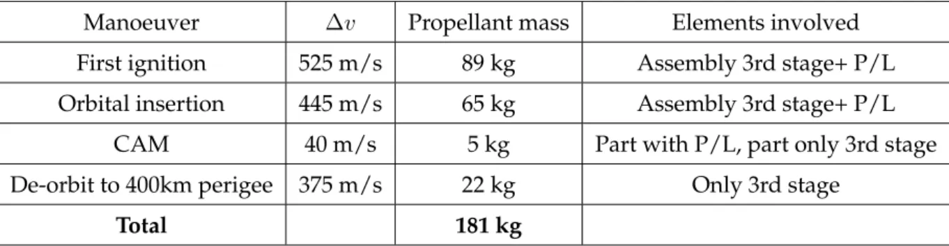
This kind of motor has been selected for the third stage of the launcher. This engine can provide the following functions:
• to insert the launcher into the transfer orbit,
• to insert the launcher from the transfer orbit into the payload final orbit,
• to perform orbital manoeuvres for collision avoidance and for multi-payload release,
• to perform de-orbiting manoeuvre for the third stage, when this is required by the debris mitigation policy.
Propulsion functions are implemented by the well-proven Astrium S400-12 bipropellant engine, which has been selected for its performances, reported in figure 2.9, and reliability.
The third stage accommodates also the payload, an attitude control system and most of the avionic system.
2.2. THE VEHICLE PROPULSION DESIGN
Throat diameter 16.4mm Nozzle end diameter 244mm Nozzle expansion ratio 244mm Mass engine with valve 3.60kg Thrust,nominal, in vacuum 420N
Specific impulse,nominal 318 Thrust range 340-440N Mass flow rate,nominal 135g/s
Mass flow rate,range 110-142g/s Mixture ratio,nominal 1.65
Mixture ratio,range 1.50-1.80 Chamber pressure 10bar Qualified single burn life 1.1hrs Qualified accumulated burn life 8.3hrs Qualified cycle life 100hrs
Figure 2.9:S400-12 engine characteristics
Thrust level provided by one single engine would be sufficient to perform the manoeuvre but long firing due to the low resulting acceleration impacts on the manoeuvre precision. For example a total amount of 1000 m/s will be needed to insert the vehicle properly on a 600 km orbit, and the burning time will be about 1200s.
Moreover, a lower firing time would allow to increase the precision of the manoeuvre. A possible solution would be to increase the number of the engines, but this would increase also the propulsion system mass. Therefore, taking into account these aspects, the third stage have been provided with only two of these engines.
The internal volume of the third stage encloses the propulsion system together with the two tanks for MMH and N2O4with the pressurant tank of helium. Instead, the avionics
unit have been accommodated on the external surface of the third stage structure. A thermal protection shield could be required for protecting the electronic units from plume radiation.