DOTTORATO DI RICERCA IN INGEGNERIA MECCANICA INDUSTRIALE
CICLO DI DOTTORATO
XXVI
COOL MATERIALS PERFORMANCES
ANALYSIS IN BUILDING AND URBAN SCALE
DOTTORANDO:
Emiliano Carnielo
TUTOR:
Prof. Ing. Aldo Fanchiotti
COORDINATORE:
Climate changes have in global warming one of the most obvious manifestations. The increase in temperature is a generalised phenomenon, associated with a number of environmental energy risks. The urban heat island is a typical effect, in which global phenomena are in addition to specific local conditions that lead to significant temperature rises in densely urbanised areas with respect to rural ones. Another trend is the increase in consumption for air conditioning in summer and, consequently, of electricity in the civil sector, as demonstrated by data collected in recent years, at national and European level, regarding consumption by sector.
Cool materials represent a possibility to mitigate both phenomena, since they allow to reduce the overheating of construction materials due to the high absorption of solar radiation. Cool materials, characterised by high solar reflectance and thermal emissivity, have many possible applications and are the subject of numerous studies to optimise their thermal-physical properties and check their effects on urban area and on buildings. This study aims at evaluating the efficiency of the cool material both on building scale and on urban scale.
Among cool materials there are products used as building roof coatings, the so-called cool roofs. These products are available in the European market for nearly a decade and nearly two decades in American ones. Although they are a consolidated technology, their use remains limited to a few buildings mostly experimental. This also makes impossible to massively exploit their properties.
Within this report, the application of a cool roof has been tested on a single floor building with a low-sloped roof. The experimental and numerical analyses have shown the potential of this passive technique on increasing in thermo-hygrometric comfort influencing the decrease in internal temperatures of about 2.5 °C as well as the energy savings associated with the energy demand for cooling.
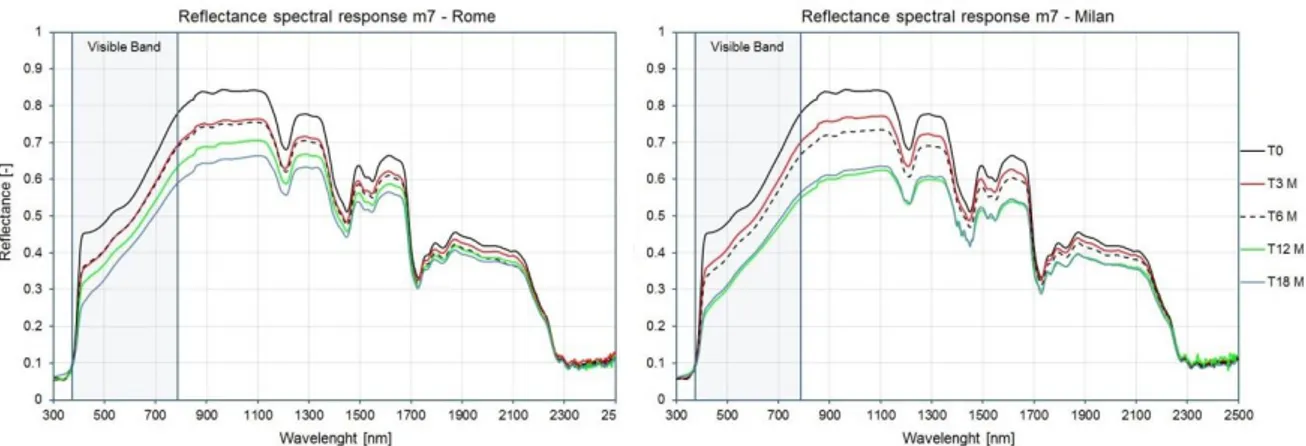
A little investigated aspect of this technology is the study of the decay of the reflection power related to natural phenomena of ageing and soiling. A measurement campaign still in progress aims at assessing the reflectance of materials used as roof coatings with regular experimental analyses. After 18 months there was a decrease of about 24% of the reflection power for samples that had an initial solar reflectance greater than 0.8. In general, this decay is a function of roughness and reflectance spectral response shape. Nonetheless in many cases spectral data measured after 12 and 18 months demonstrate a convergence trend with broadband values however higher than that of conventional materials.
Despite the benefits reported in this and other studies on real applications, there are no procedures for the energy classification of these materials. National energy policies are aimed at reducing consumption related to space heating, with restrictions on thermal transmittance values of the building envelope, neglecting those related to space cooling. For this reason it has been proposed a cool roof classification system as a function of their thermal properties and their influence on the energy performance of buildings normalised as a function of the geometry of some reference buildings and climatic zones.
The cool materials used for urban applications as asphalt and concrete tints, the cool paving, are a technology still in its infancy, with a negligible market penetration. The optical and solar characterisation of these products confirmed their high reflectance especially compared to conventional materials with surface temperatures even lower than 20 °C. A lower surface temperature reduces the heat transferred to the air for convection. The potentialities of these materials applied on the asphalt of a neighbourhood of Rome were analysed by numerical analysis with a type SVAT tool (Soil, Vegetation, Atmosphere, and Transfer). Results showed a decrease in average air temperature of 5.5 °C compared to those obtained in presence of conventional asphalts. The temperature decrease is also reflected at an altitude over the average height of buildings. This shows how cool materials, when used on an urban scale, can be exploited as a contributory factor to the reduction of the heat island.
the reflectance as a constant and independent on the incidence angle of radiation that hits the surfaces (Lambertian reflection). Instead, the building materials, especially those used as roof coatings, present mixed reflection modalities with not negligible regular components, which are a function of angle of incidence as demonstrated in the experimental campaign shown in this report. Thus, it was obtained a function that linked the solar reflectance to incidence angle starting from the measured data. It has been used in order to modify the calculation model of a dynamic tool in order to optimise the solar gains calculation. The results demonstrate the limits of current thermo-physical models generally used to conduct energy analyses.
I cambiamenti climatici hanno nel riscaldamento globale una delle manifestazioni più evidenti. L‘aumento delle temperature è un fenomeno generalizzato, cui si associano una serie di rischi ambientali ed energetici. L‘isola di calore urbana è un tipico effetto, in cui fenomeni globali si sommano a specificità locali che portano ad innalzamenti di temperatura significativi in aree densamente urbanizzate. Altra tendenza è l‘aumento dei consumi per la climatizzazione estiva e, conseguentemente, di energia elettrica nel settore civile, come dimostrato dai dati raccolti in questi anni su scala nazionale ed europea riguardanti i consumi per settore.
I cool material rappresentano una possibilità per mitigare entrambi i fenomeni, dal momento che consentono di ridurre il surriscaldamento dei materiali da costruzione per effetto dell‘elevato assorbimento della radiazione solare. I cool material, caratterizzati da riflettanza solare ed emissività termica elevate, hanno numerose possibilità applicative e sono oggetto di numerosi studi per ottimizzarne le proprietà termo-fisiche e verificarne gli effetti su aree urbane e sugli edifici. Questo studio ha lo scopo di valutare l’efficienza dei cool material sia su scala di edificio sia su scala urbana.
Tra i cool material esistono dei prodotti utilizzati come rivestimento per i tetti degli edifici, definiti cool roof. Tali prodotti sono presenti nei mercati europei da circa un decennio e da circa due decenni in quelli americani. Sebbene siano una tecnologia ormai consolidata, il loro utilizzo resta limitato a pochi edifici perlopiù sperimentali. Ciò non rende possibile uno sfruttamento massivo delle loro proprietà.
All’interno di questa relazione, è stata testata l’applicazione di un cool roof su un edificio sviluppato su un piano singolo con tetto orizzontale. Le analisi sperimentali e numeriche hanno dimostrato le potenzialità di questa tecnica passiva sia sul benessere termo-igrometrico, influendo sulla diminuzione delle temperature interne di circa 2.5 °C, sia sul risparmio energetico associato alla richiesta di energia per il raffrescamento.
Un aspetto poco investigato di questa tecnologia riguarda lo studio del decadimento del potere di riflessione legato a fenomeni di invecchiamento e sporcamento naturali. Una campagna di misura tuttora in atto ha come obiettivo la valutazione della riflettanza di materiali utilizzati come rivestimento dei tetti con analisi sperimentali periodiche. Dopo 18 mesi è stata riscontrata una diminuzione di circa il 24% del potere di riflessione per i campioni che presentavano una riflettanza solare iniziale superiore a 0.8. In generale questo decadimento è funzione della rugosità e dello spettro di riflessione. Nonostante ciò, in molti casi, i valori di riflettanza spettrale misurati dopo 12 e 18 mesi sembrano iniziare a convergere con valori integrati comunque più alti rispetto a quelli dei materiali convenzionali.
Nonostante i benefici rilevati in questo e in altri studi su applicazioni reali, non esistono procedure di classificazione energetica di questi materiali. Le politiche energetiche nazionali sono mirate a ridurre i consumi legati al riscaldamento degli edifici, con restrizioni sempre maggiori sui valori di trasmittanza termica dell’involucro edilizio, trascurando invece quelli legati al raffrescamento estivo. Per questo motivo è stato proposto un sistema di classificazione per i cool roof in funzione delle loro proprietà termiche e della loro influenza sulle prestazioni energetiche degli edifici normalizzate in funzione della geometria di alcune strutture di riferimento e delle fasce climatiche.
I cool material utilizzati per applicazioni urbane come tinte per asfalti e calcestruzzi sono una tecnologia ancora in fase embrionale, con una trascurabile penetrazione nei mercati. La caratterizzazione ottica e solare di questi prodotti ha confermato la loro elevata riflettanza soprattutto rispetto ai materiali convenzionali con temperature superficiali, rispetto a questi ultimi, anche inferiori di 20 °C. Una temperatura superficiale inferiore riduce il calore ceduto all’aria per convezione. Le potenzialità di questi materiali applicati sull’asfalto di un quartiere di Roma sono state analizzate tramite analisi numeriche con un software di tipo S.V.A.T. (Soil, Vegetation, Atmosphere, Transfer). Si sono ottenute diminuzioni della temperatura media dell’aria anche di 5.5
diminuzione dell’effetto isola di calore.
L’utilizzo di diversi software per l’analisi energetica impiegati come strumento numerico ha permesso di evidenziare un limite riguardante la modellizzazione delle superfici degli edifici. Questi modelli considerano la riflettanza come costante e indipendente dall’angolo di incidenza della radiazione che li colpisce (riflessione Lambertiana). In realtà i materiali da costruzione, soprattutto quelli utilizzati per il rivestimento superficiale dei tetti, presentano modalità di riflessione miste con componenti regolari, che sono funzione dell’angolo di incidenza, a volte non trascurabili come dimostrato nella campagna sperimentale riportata in questa relazione. È stata ricavata quindi una funzione che legasse la riflettanza solare all’angolo di incidenza a partire dai valori misurati. Essa è stata utilizzata in modo da modificare il modello di calcolo di un software dinamico al fine di ottimizzare il calcolo dei carichi solari. I risultati hanno dimostrato i limiti dei modelli termo-fisici generalmente utilizzati per condurre analisi energetiche.
It was possible to carry out this work thanks to the funds allocated by the Italian Ministry for Economic Development under the framework of RSE - Ricerca Sistema Elettrico, for the following projects:
Impatto di tecnologie Cool Roof sulle prestazioni energetiche degli edifici. Caso studio; Impatto di tecnologie Cool Roof sulle prestazioni energetiche di edifici residenziali in area
mediterranea;
Impatto delle protezioni solari trattate con vernici innovative ad elevata riflettanza all'infrarosso vicino sulle prestazioni energetiche di edifici residenziali in regime estivo; Impatto di cool material sulla mitigazione dell’isola di calore urbana e sui livelli di comfort
termico negli edifici;
Determinazione delle proprietà termofisiche di materiali ad elevata riflettanza solare per applicazioni a scala urbana: limiti e potenzialità;
Caratterizzazione e valutazione di pavimentazioni riflettenti per applicazioni urbane. Ricerca di sistema elettrico;
Sviluppo di materiali e tecnologie per la riduzione degli effetti della radiazione solare.
Moreover a special thanks goes to Prof. Aldo Fanchiotti of Engineering Department of Roma Tre University for giving me the opportunity to carry on this research, to Dr. Michele Zinzi of UTEE of ENEA Casaccia Research Centre for the forwarded experience, to Dr. Tiziana Poli and to Dr. Riccardo Paolini of ABC Department of Politecnico di Miliano and to Dr. Giuseppe Rossi of INRIM for their technical and theoretical support.
ABSTRACT ... 2 SINTESI ... 4 ACKNOWLEDGEMENTS ... 6 SECTION 1: OVERVIEW ... 11 1. Introduction ... 12 1.1 Research Topic ... 12 1.2 General Framework ... 12
1.3 Cool Materials: Properties ... 16
1.4 References ... 18
2. Theoretical references ... 19
2.1 Introduction ... 19
2.2 Nomenclature... 20
2.3 Solar Radiation and Optical Quantities ... 20
2.3.1 Solar Radiation Characteristics ... 20
2.3.2 Materials and Solar Radiation ... 22
2.3.3 Optical and Solar Properties of Materials ... 24
2.4 Wall Exposed to Solar Radiation ... 24
2.5 Outline of Black Body Theory ... 26
SECTION 2: EXPERIMENTAL AND NUMERICAL ANALYSES ... 29
3. Instruments for solar and thermal characterisation of materials ... 30
3.1 Introduction ... 30 3.2 Nomenclature... 31 3.3 Spectrophotometer ... 31 3.3.1 Commercial Spectrophotometer ... 32 3.3.2 Experimental Facility ... 34 3.4 Gonio-Photometer ... 35 3.5 Emissometer ... 39 3.6 References ... 40 4. Cool Roofs ... 41 4.1 Topic ... 41
4.2.2 Cool Roof Types ... 42
4.2.3 Main Cool Roof Products ... 43
White Cool Roofs ... 43
Metal Materials ... 43
Cool Coloured Materials ... 44
Other Cool Materials ... 44
Thermo-Chromic Materials ... 44
4.3 Case study: Cool Roof Application in a Non-Residential Building ... 45
4.3.1 Building Description ... 45
4.3.2 Cool roof application ... 47
4.3.3 Methodology ... 47
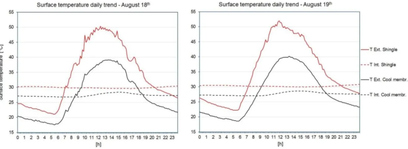
4.3.4 Experimental ... 47
Optical and Thermal Characterisation of Roof Coating Surfaces ... 47
Positioning of the Outdoor Equipment ... 48
A Drawback for the Membrane ... 49
Comparative Analysis of Measured Data ... 50
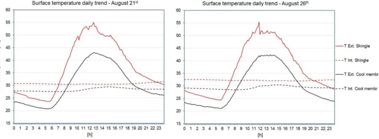
4.3.5 Numerical Analyses ... 52
The Software ... 52
The Model ... 52
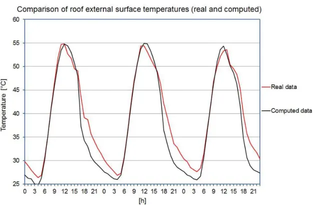
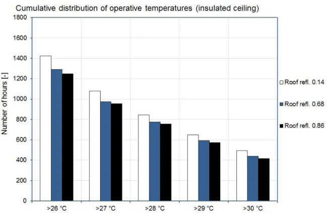
Simulations Results: Operative Temperatures ... 54
Simulations Results: Cooling Energy Demands ... 56
4.4 Effects of Ageing and Soiling on Solar Reflectance of Roofing Membranes ... 58
4.4.1 Nomenclature ... 58
4.4.2 Selected Materials ... 59
4.4.3 Exposure Sites and Sample Positioning ... 59
4.4.4 Methodology ... 59
4.4.5 Experimental Results ... 60
4.5 Cool Roofs Energy Rating System Proposal ... 66
4.5.1 Methodology ... 66
4.5.2 Climatic Conditions ... 67
4.5.3 The Reference Buildings ... 67
4.5.4 Numerical Analysis ... 68
Software ... 68
Climate Independent Cooling Energy Rating ... 74 4.6 Chapter Conclusions ... 76 4.7 References ... 76 5. Cool Paving ... 78 5.1 Topic ... 78 5.2 Introduction ... 78
5.3 The Urban Heat Island effect ... 80
5.3.1 Measurement of the Intensity of the Urban Heat Island in the City of Rome ... 81
5.4 Photo-Catalytic Tints for Asphalts... 86
5.4.1 Samples Description ... 86
5.4.2 Methodology ... 86
5.4.3 Experimental ... 86
Thermo-Graphic Analysis ... 86
Solar and Optical Characterisation ... 87
Surface Temperatures Analysis ... 88
5.5 Porous Concrete Draining Paving ... 91
5.5.1 Selected Materials ... 91
5.5.2 Experimental ... 91
5.6 Calculation of Urban Environment Temperatures: Numerical Analysis... 93
5.6.1 Description of the Calculation Software: ENVI-met ... 93
5.6.2 ENVI-met Model of a Neighbourhood of Rome: Prati ... 93
5.6.3 Simulations Result ... 97
Buildings and Asphalt Surfaces ... 97
Asphalt Surfaces: Photo-Catalytic Tints ... 101
Asphalt Surfaces: Concrete Draining Paving ... 106
5.7 Chapter Conclusions ... 111
5.8 References ... 111
SECTION 3: DEVELOPMENT OF NUMERICAL METHODS ... 114
6. Solar reflectance angular dependence of opaque construction materials ... 115
6.1 Introduction ... 115
6.2 Nomenclature... 116
6.3 Methodology ... 116
6.6 Spectrophotometric Measurements ... 123
6.7 Comparison Between the Two Instruments Results... 126
6.8 Numerical Analysis Calculation ... 127
6.8.1 Preliminary Comparisons Between Experimental and Theoretical Solar Reflectance .... 127
6.8.2 Model Description ... 129
6.8.3 Results ... 129
6.9 Chapter Discussions and Conclusions ... 133
6.10 References ... 133
7. Conclusions ... 134
7.1 Achievements ... 134
1. Introduction
1.1
Research Topic
This research is focused on the study of the efficiency of innovative materials used as passive technique for energy savings in buildings and as a contributory factor to limit the overheating phenomenon of urban areas: the urban heat island. These materials, characterised by high solar reflectance and thermal emissivity, were the subjects of tests carried out in laboratory and outdoors. The results supported by numerical analysis allowed to establish their limits and potentialities.
1.2
General Framework
Phenomena such as climate change and global warming are known to the public opinion, as well as the associated risks. They are present on a global scale, regardless of latitude and economic development, although with different intensity and consequences. One of the areas at risk is the Mediterranean basin with a predicted rise in average air temperatures of 2 °C by 2030 and even further by 2100 [1.1]. Some estimates foreshadow very drastic scenarios: increase of tropical nights, where the temperature never drops below 20 °C and 30% reduction in annual rainfall in comparison to the current standards.
The data on the increase of the concentration of carbon dioxide show a strong link to the anthropogenic activities. The trend shown in Figure 1.1 highlights how radically changed the amount of CO2 emissions resulting from fossil fuels in atmosphere since the mid-1700s. Emissions
are literally exploded in the second half of the twentieth century in large part due to energy uses. The data comes from CDIAC (Carbon Dioxide Information Analysis Center) of the Department of
The increase of CO2 concentration in atmosphere, the main greenhouse gas, has a significant
impact on temperature rising. From this point of view, it is interesting to observe the evolution in Figure 1.2. The figure refers to the annual average temperature of the Earth surface. It is important to note the growing trend, especially in recent decades. Once again, data confirm a planet thermal equilibrium alteration due to anthropogenic factors.
A much debated topic wonders if these changes are natural or caused by human activity, being the second option considered the most plausible by the majority of the scientific community. The latter argues that global warming will lead to many irreversible risks and changes if the increase in temperature will exceed 2 °C.
Figure 1.1: CO2 emissions in atmosphere since 1700.
Figure 1.2: Annual average temperature of Earth surface (source: NASA).
Most of development and production activities of industrialised countries required an enormous amount of energy produced and used. All this happened for decades and only in the last 20 - 30 years the energetic and environmental problems have been globally recognised, without arriving at shared solutions to limit it. Furthermore, the appearance of new and formidable economies makes this problem resolution definitely more complex.
Some interesting data are retrievable from RAEE (Rapporto Energia e Ambiente), annually published by ENEA [1.2]. The global energy end uses in 2009 amounted to about 7.5 billion of toe (tons of oil equivalent, a unit of measurement that expresses the energy released by the combustion of a ton of oil) corresponding to an increase by 34% if compared to 1990.
The previous figure is alarming but in the euro zone the trend is downward. Looking at the national data, considering the available data, the energy end uses decreased of about 5.2% from
2011 to 2012, following the positive trend of the previous year in which they decreased of about 2.65%. In fact the end uses consumptions reached in these years the values they had in 1997 denoting a collective effort that has reversed the trend of growth.
On the other hand, ENEA data also reported that the civil sector does not follow this positive trend. The impact of this sector on total energy end uses increased from 30.8% in 2004 to 36.7% in 2012, proving to be the sector with the highest energy consumption in Italy. Figure 1.3 shows the distribution of end uses of energy sector for the year 2012.
Figure 1.3: Percentage distribution of energy end uses in Italy, 2012 (source: Data processing by ENEA - Data provided by the Italian Ministry of Economic Development).
Figure 1.4 shows the energy consumption trend for the main sectors over the years. In the last years the civil sector (residential and services) has overtaken the industry, which has experienced a period of undeniable energy efficiency, and the transport sector, traditionally the more consistent consumption item.
Figure 1.4: Energy end uses trend by sector (source: Data processing by ENEA - Data provided by the Italian Ministry of Economic Development).
(+0.8% from 2010 to 2011), the services sector shows a strong increasing trend. In particular, the electricity consumption per worker in trade sector has more than doubled in the last twenty years.
The constant increase in sales of compact units for air conditioning and in size of large cooling systems, demonstrates the critical point, as well as the increasing in comfort demand from the growing population.
The phenomenon seems to be linked to the continuous urbanisation which sets in motion millions of people from rural to urban and suburban areas, with significant problems of environmental degradation. One of these problems is the urban heat island effect, a phenomenon for which the average or peak temperatures of urban areas becomes a few degrees higher than the ones of rural areas.
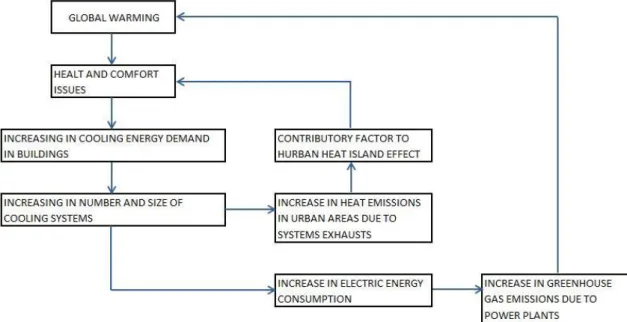
The aspects related to energy and environmental issues listed in this paragraph assume an even more serious connotation considering that they are related in a cyclic manner, as shown in Figure 1.5.
Figure 1.5: Cause and effect diagram of energy and environment problems.
The need to cool buildings and cities become crucial in a context of great environmental commitment recruited on an international scale. The problem is not only Italian; in fact buildings are responsible for the 40% of global energy consumption in the European Union. Therefore, in the European Directive 91/2002 issued by the European Parliament the dictates to follow to reduce energy consumption in buildings are reported [1.3]. The Directive covers different fields and introduces key aspects such as energy certification of buildings, the requirement to take into account for the different energy uses and not only for heating, i.e.: cooling demand; ventilation; lighting; production of domestic hot water. In 2010 was enacted the Directive 31, which updates the Directive 91/2002, introducing other aspects, such as the obligation to almost zero energy consumption for new buildings here in a few years [1.4]. The ultimate goal is to contribute to the achievement of the reduction of greenhouse gas emissions by 20% compared to 1990 levels by 2020 as required by the Kyoto Protocol.
Many techniques for energy saving in buildings were proposed in recent years. Some proposals are related to increase cooling and heating systems performances, such as systems that use absorption heat pumps powered by hot fluids obtained as result of regeneration or through solar collectors (solar cooling). Unfortunately, these systems have very high initial costs that justify their use only for high peak powers and therefore are not suitable for residential use. In Europe, thanks to incentive policies, household photovoltaic systems are taking hold to allow to feed with the electrical energy stored in batteries the heat pumps for heating and cooling.
There are also passive techniques designed to make the building envelope more efficient. Among these, there are some that are aimed at a reduction of solar load on the external surfaces. The study concerning solar gains through the opaque components of the building envelope is assuming significant importance in both residential and non-residential buildings. The need to improve the energy performance of buildings, reducing energy consumption for cooling is leading to the development of new materials that are designed to modulate solar gains. These materials represent a viable and economical technique for passive cooling of buildings. They are characterised by a higher reflection power of solar radiation than conventional materials and, used as coatings for external surfaces, play an important role in the heat exchange. These products are defined “cool materials”.
The high reflection limits the increase of surface temperature in presence of solar radiation, reducing both the heat exchanged with the environment by convection and the incoming heat in buildings by conduction. The final consequence is, in the first case, the urban heat island reduction, in the second case the cooling demand reduction in buildings. Projects and studies conducted in recent years show the impact of technology by means of numerical analysis [1.5 - 1.9], and by means of experimental campaigns in real buildings [1.10 - 1.17].
1.3
Cool Materials: Properties
Cool materials are a passive technique used for energy savings. They are used as coatings for the building envelope. This technology is based on a high solar reflectance and a high thermal emissivity.
The reflectance is a characteristic of materials surface. It is defined as the ratio between the intensity of the radiant flux reflected from a surface and the radiant flux incident on it (see paragraph 2.3.2). Cool materials have a high reflectance in the solar spectrum.
Figure 1.6 shows the solar spectrum emission outside atmosphere and at sea level. Having an ideal white colour surface means reflecting the full emission spectrum in the visible band (380 - 780 nm), at each wavelength, equivalent to approximately 55% of the whole power contained in the solar spectrum. Having an ideal black colour material means absorbing the whole energy emission of the visible band. This is the reason why the light colours materials tend to heat up less compared to dark colour materials. The phenomenon is well known and used in the building since ancient times as shown in Figure 1.7 which shows an ancient structure in use in southern Italy: The “trullo”.
Figure 1.7: Trullo in southern Italy.
Figure 1.6 also highlights how the sun emits a significant amount of energy over the visible band and distributed in a larger band: The NIR band (Near Infra-Red) that ranges from 780 to 2500 nm. A high reflection power in this band is the peculiar characteristic of cool materials.
High reflection in visible band depends mainly on the surface colour, while the cool materials have a high reflectivity in the entire solar spectrum being equal the surface colour reflecting a greater amount of solar radiation compared to a conventional material. This depends on the reflectance in the NIR band.
For example Figure 1.8 shows the reflectance as a function of wavelength, in the solar spectrum of two materials with the same colour, one of which is a cool coloured material [1.17]. The colour of these materials is dark grey, for this reason the reflectance in the visible band remains below 0.1. Beyond 780 nm the reflectance of the conventional material stay at a nearly constant value between 0.05 and 0.07, while the reflectance of the cool coloured material increases in a clear manner, reaching a peak value of 0.7 at 1600 nm, greater than an order of magnitude compared to the conventional material one.
To express the physical concept of thermal emissivity, it is useful to take into account the theory of the black body (see paragraph 2.5). It is a physical entity capable of absorbing the full electromagnetic radiation and, for the energy conservation, is able to re-irradiate (or emit) it entirely.
The emittance of a body is the ability that the body has to emit a quantity of energy at a certain temperature and it represents a power per unit area (W / m2).
The emissivity is defined as the ratio between the global emittance of a real body and the global emittance of a black body at the same temperature considered.
The construction materials typically have a very high value of emissivity of around 0.9 with the exception of the metals which have lower values (0.2 - 0.7). Generally cool materials have a high thermal emissivity in order to facilitate the dissipation during the night of the heat accumulated during daylight hours due to radiative and convective heat transfer.
1.4
References
[1.1] Climate change: Intergovernmental Panel on Climate Change (IPCC); 2007.
[1.2] RAEE Rapporto Annuale Efficienza Energetica: ENEA; 2014. www.ENEA.it; available online at. [1.3] Eu Directive 2002/91/Ec. On The Energy Performance Of Buildings; 2002.
[1.4] Eu Directive 2010/31. On The Energy Performance Of Buildings (recast); 2010.
[1.5] Akbari H, Bretz S, Kurn D, Hartford H. ‘Peak power and cooling energy savings of high albedo roofs’. Energy and Buildings; 1997; 25: 117 - 126.
[1.6] Christen A, Vogt R. ‘Energy and radiation balance of a central European city’. International Journal of Climatology; 2004; 24: 1395 - 1421.
[1.7] Suehrcke H, Peterson EL, Selby N. ‘Effect of roof solar reflectance on the building heat gain in a hot climate’. Energy and Buildings; 2008; 40: 2224 - 2235.
[1.8] Synnefa A, Santamouris M, Akbari H. ‘Estimating the effect of using cool coatings on energy loads and thermal comfort in residential buildings in various climatic conditions’. Energy and Buildings; 2007; 39(11): 1167 - 1174.
[1.9] Zinzi M. ‘Cool materials and cool roofs: Potentialities in Mediterranean buildings’. Advances in Building Energy Research; 2010; 4: 201 - 266.
[1.10] Bozonnet E, Doya M, Allard F. ‘Cool roofs impact on building thermal response: A French case study’. Energy and Buildings; 2011; 43(11): 3006 - 3012.
[1.11] Carnielo E, Fanchiotti A., Zinzi M. ‘Energy and comfort benefits of a cool roof application in a non - residential building belonging to Roma Tre University’. World Renewable Energy Congress, 8 -13 May, Linköping, Sweden; 2011.
[1.12] Kolokotsa D, Diakaki C, Papantoniou S, Vlissidis A. ‘Numerical and experimental analysis of cool roofs application on a laboratory building in Iraklion’. Energy and Buildings; 2011; 55: 85 - 93.
[1.13] Paolini R, Zinzi M, Poli T, Carnielo E, Fiori M, Mainini AG. ‘Evolution over time of UV – VIS - NIR reflectance of cool roofing materials in urban environments’. 34th AIVC conference, 25 – 26 September, Athens, Greece; 2013.
[1.14] Parker D, Huang J, Konopacki S, Gartland L, Sherwin J, Gu L. ‘Measured and simulated performance of reflective roofing systems in residential buildings’. ASHRAE Trans; 1998; 104(1): 963 - 975.
[1.15] Romeo C, Zinzi M. ‘Impact of a cool roof application on the energy and comfort performance in an existing non - residential building. A Sicilian case study’. Energy and Buildings; 2011; 67: 647 - 657. [1.16] Synnefa A, Saliari M, Santamouris M. ‘Experimental and numerical assessment of the impact of
increased roof reflectance on a school building in Athens’. Energy and Buildings; 2012; 55: 7 - 15. [1.17] Zinzi, M, Carnielo E, Agnoli S. ‘Characterization and assessment of cool coloured solar protection
2. Theoretical references
2.1
Introduction
The building envelope is the boundary which delimits the built environment from the external one and, for that reason, it is subject to a series of thermal fluxes, having a direction dependent on external and indoor conditions.
Referring to Figure 2.1, the following thermal fluxes can be highlighted:
Transmission: A function of temperature difference between indoor and outdoor;
Solar gains: A function of solar radiation, both direct and diffuse, which affects opaque and transparent surfaces;
Ventilation: Outdoor air intentionally introduced into the environment to ensure the indoor air healthiness;
Infiltration: Amount of the non-controlled air that penetrates through the building envelope, which is not perfectly sealed.
According to the European Directive EPBD and later recast in 2010, energy uses to be considered in the energy balance of building are: heating, cooling, ventilation, lighting, hot water. The opaque components of the building involved in energy balance by influencing the cooling and heating demand.
This chapter describes the main thermo-physical properties of the opaque components and illustrates the way in which they enter into the heat balance of the building. These basics are necessary for fully understanding the following chapters, in which the characteristics of different materials used as building coatings will be widely discussed.
Figure 2.1: Heat fluxes affecting the building envelope.
2.2
Nomenclature
Table 2.1 shows the symbols reported in chapter 2.
Table 2.1: Chapter 2 nomenclature.
2.3
Solar Radiation and Optical Quantities
2.3.1
Solar Radiation Characteristics
The sun is a gaseous spherical mass with a diameter equal to 1.4 · 106 km and a temperature on the order of millions of degrees in the central regions, which emits energy in the form of oscillating electromagnetic field. Among the many chemical reactions that take place inside the star, there is the fundamental transformation of hydrogen into helium, a reaction that gives rise to spontaneous emission of energy. The energy is then transferred through convection to the sun surface and radiated into the space according to a very complex process. Solar radiation is the result of many layers that emit and absorb radiant energy at variable wavelengths. In the physical-technical analysis is permissible to approximate the sun as a black body having an effective temperature that range about between 5800 and 6300 K.
The sun is located at a distance from the Earth equal in average to 1.495 · 1011 m (about 150 million km), with a variation of ± 1.7 %, due to the elliptical shape of the trajectory of motion of the Earth around the star. The characteristics of the sun and the geometric relationships between it and the Earth induce almost constant intensity of solar radiation outside the atmosphere. This consideration allows to introduce the solar constant Is, a quantity defined as the energy coming
from the sun which affects, in the unit time, the unit area of a surface perpendicular to the direction of radiation propagation and placed in the space at a distance equal to the average distance Earth-Sun. The most recent measurements assign to the solar constant a value between 1353 - 1367 W/m2.
In addition to the total energy emitted by the sun, it is also important to know its spectral distribution. The emitted radiation is actually the overlap of a series of waves having wavelengths in a range theoretically infinite, but practically between 150 nm and 10 µm. The following spectral portions can be therefore identified:
Ultraviolet spectrum (150 - 380 nm), harmful to health and to the deterioration of many materials, particularly plastic ones (polymerisation);
Visible spectrum (380 - 780 nm), part of the solar spectrum that is sensitive to the human eye and, therefore, the most important for the study of natural lighting;
Infrared spectrum (780 nm -10 microns), spectral area with significant impact on heat transfer. Reference standards define as NIR (Near Infra-Red) a region between 780 and 2500 nm. Medium and far infrared are related to portions of spectrum to higher wavelength. The spectral distribution of solar radiation indicates that about 7% of the radiation falls within the ultraviolet spectrum, about 55% in the visible spectrum and the rest in the NIR spectrum being the contribution in the far infra-red only a few percentage points. It is important to note that the spectral distribution, beyond its own nature, is often defined differently in various international standards.
Figure 2.2 shows the spectral trend normalised to the peak of the solar radiation and the cumulative distribution of the radiation itself, which shows that more than 90% of solar energy falls within 1700 nm.
The radiation coming from the sun propagates as a beam of parallel rays but, in crossing the atmosphere, undergoes three changes, due to the effect of the gases, water vapour, water droplets and suspended solid particles which constitute the atmosphere itself:
A substantial reduction, due to the fact that the radiation is partly absorbed by the atmosphere and in part reflected to the outer space;
A variation of the spectral distribution, due to the selective behaviour of some of the atmosphere components (O2, O3, CO2, H2O);
A dispersion in the atmosphere (scattering), due to multiple reflection phenomena that diffuse the radiation reaching the ground in addition to the collimated one coming directly from the direction of the sun (direct radiation).
The consistency of these phenomena depends on thickness and composition of the atmosphere layer passed through by the radiation. It is useful to remember that the solar constant is a value much higher than the normal values found on Earth surface both for filtering effect due to the atmosphere and for the geometrical conditions between the sun and an oriented surface. Hence, the amount of stored solar energy in a surface depends on the inclination and orientation of the surface itself. Figure 2.3 shows the monthly average values of solar radiation (W / m2) on surfaces oriented in a different way, and this demonstrates what is stated above.
Figure 2.3: Monthly average solar radiation for several orientations – Rome.
2.3.2
Materials and Solar Radiation
When solar radiation hits a surface material is decomposed into several components as a function of parameters that affect the characteristics of the radiation, such as the spectral distribution, the angle of incidence, and the material type.
Solar reflection can be transmitted, reflected and absorbed:
The ratio between the transmitted radiation and the incident radiation is called transmittance, generally indicated with “τ”.
The ratio between the reflected radiation and the incident radiation is called reflectance, generally indicated with “ρ”.
The ratio between the absorbed radiation and the incident radiation is called absorptance, generally indicated with “α”.
These quantities can be expressed similarly in dimensionless value (from 0 to 1) or with a percentage (from 0% to 100%). The three coefficients are related by the following equation.
Opaque materials, for their own definition do not allow to be passed through by solar radiation, for this reason τ = 0. The previous equation 2.4 becomes:
These quantities are not constant if considered in the whole solar spectrum but they depend on wavelength. The equation 2.2 can be rewritten as:
And similarly it is possible to rewrite the quantities reported in equations 2.1 and 2.3. Figure 2.4 shows the spectral reflectance trend of an opaque material.
It has to be noted that the reflectance indicates only the amount of radiation reflected and nothing about the way in which the phenomenon occurs. This clarification is essential when treated opaque materials in densely urbanised areas to avoid concentrated inter-reflections both for health and safety issues. The incident radiation can be reflected in such a way:
Regular, the beam is reflected with an angle equal to the angle of the incident radiation; Diffuse (Lambertian), according to the cosine law, the incident beam is reflected as the sum
of infinite rays emitted in all directions following the equation:
The reflected radiation, in the direction defined by the angle θ, that the direction itself do with the surface normal, is equal to the normal reflected radiation multiplied by the cosine of the angle. The materials of this type are purely theoretical and do not exist in nature. The term “diffuse” generally refers to those materials that have an opening angle with respect to the normal between 60° and 90° (being the latter the angle of a Lambertian material);
Partially diffuse (scattering), the incident beam is reflected more or less diffusely, keeping a preferential direction as a function of the incidence angle.
Those considerations can be applied similarly to transmittance and absorptance.
2.3.3
Optical and Solar Properties of Materials
The spectral quantities for practical applications can be traced to singular broadband values, by means of integration operations on reference spectra.
Referring for simplicity only to reflectance, it is defined solar reflectance (indicated with subscript “e”) the value expressed by the following equation.
∫
∫
having indicated with the reference solar spectrum, the integration limits are the reference solar spectrum limits. Likewise it is defined the luminous or visible reflectance (indicated with the subscript “v”) the value expressed in the following equation.
∫
∫
The spectral reflectance is multiplied by two reference curves: One corresponding to a white illuminant and one corresponding to the sensitivity curve of the human eye . The integration limits correspond to minimum and maximum wavelength detected by the human eye.
2.4
Wall Exposed to Solar Radiation
In paragraph 2.1 solar gains have been defined as one of the main thermal fluxes involved in the energy balance of a building. This section is intended to define how they can be included in the calculation of the heat exchange through a flat wall, giving for granted the other basic concepts.
In the hypothesis of steady thermal flux a flat wall composed by “n” layers separates two environments characterised by two different temperatures and . The thermal transmittance
“ ” of the wall is (see table 1 for the used symbols):
The wall is hit by solar radiation [W/m2] on the external surface. The wall absorbs " " being " " its solar absorptance.
The layer of the wall which absorbs the radiation reaches a temperature Ts in order to ensure
the balance, namely that the radiation absorbed by the unit area in the unit time is transferred from the layer both outwards ( ) and through the wall ( ) to environment with temperature :
The two heat fluxes can be expressed as the ratio between the corresponding difference in temperatures and the thermal resistances:
having indicated with B and the inverse of the sum of all the resistances offered by the layers of the wall plus the resistance associated to the internal adduction coefficient. Namely:
The Figure 2.5 shows the quantities taken into account in this paragraph.
Figure 2.5: Thermal fluxes in a flat wall under solar radiation.
By entering equations 2.13 and 2.14 into the equation 2.11 it is possible to find the expression for :
By entering equation 2.15 into equation 2.13 the following equation is obtained:
(
)
By dividing numerator and denominator of 2.16 for (remembering equation 2.14) the
following equation is obtained:
[
]
In this equation the term represents the equivalent temperature air-sun. It takes into
account the contribute of the solar load summing it to air temperature.
In other words, the thermal flux passing through the wall is expressed as a function of the difference between the internal temperature and this new fictitious or equivalent temperature which correspond to consider the effect of solar radiation as an increase in the temperature of the external environment. Therefore, under solar radiation, the thermal flux (calculated with 2.17) can actually be positive, facing the inside, not only when (e.g. during summer) but also when (e.g. during winter) as long as the effect of absorbed radiation by the wall, summarised
in the term
makes greater than .
2.5
Outline of Black Body Theory
In the universe all bodied have a temperature greater than 0 K and emit radiant energy. Hence a body emits radiant energy and then receives it from other bodies.
A radiative thermal flux is present whenever two or more bodies, having different temperatures, are found in the presence of each other, separated by a mean that is sufficiently transparent to radiation (such as vacuum or air). In contrast to what happened during conduction and convection, radiant energy can be transmitted even in the absence of matter, hence the study of heat transfer by radiation requires knowledge of the laws governing the emission and absorption of the bodies.
Solid state bodies have generally selective properties on energy. This means that they can emit it, reflect it, absorb it, or leave it may pass through, as a function of the wavelength.
Therefore, in order to characterise the behaviour of a body, it is not sufficient to know the extent of the radiant power globally emitted but it is necessary to know how it is distributed among the different wavelengths and in the different directions.
The following equations characterise the black body, a theoretical body with an absorption coefficient constant, whose value is equal to 1. From this equations the behaviours of the real bodies are derived. The three laws are:
1. Stefan-Boltzmann law; 2. Wien law;
3. Planck law.
The first one introduces the value , the global emittance of a black body, namely the energy globally radiated:
Where is the Stefan-Boltzmann constant = 5.67 · 10-8
[W /m2 K4].
The second one, called displacement law, provides the wavelength value for which the monochromatic emittance is maximum:
With = 2898 [μm K].
The third one expresses the distribution of the monochromatic emittance of a black body.
(
)
having indicated with: , the speed of light = 3 108
[m / s]; , the Plank constant = 6.6 · 10-34
[J s];
, the Boltzmann constant = 1.4 · 10-23
[J/K].
Referring to Figure 2.6, from the black body emission laws it can be derived that an increasing in temperature leads to:
An increase of globally emitted power, proportionally to the fourth power of absolute
temperature, based on the Stefan-Boltzmann law;
The power increases even for every wavelength, based on the Plank law, the emission
diagram moves totally towards higher values;
The maximum emission value shifts towards smaller wavelengths.
Figure 2.6: Specific emission of a black body at different temperatures: T1 = 4000 K, T2 = 3500 K, T3 = 3000 K.
In this way the black body behaviour has been characterised, but these considerations remain valid also for real bodies emitting temperature, although not black.
For them it is necessary to introduce a new quantity, the total emissivity ε that is the ratio between the relevant body global emittance and that of the black body at the same temperature.
Therefore, once the emissivity value of a real body is known, it is possible to easily calculate its fully radiative power, using the above formula.
The emissivity is another quantity that characterises the materials used as building coating. A material with a high emissivity is able to easily re-emit the heat accumulated, due to the solar loads.
Section 2: Experimental and
Numerical Analyses
3. Instruments for solar and thermal
characterisation of materials
3.1
Introduction
The reflectance and transmittance in solar, visible and NIR band together with the thermal emissivity are basic values to evaluate the performance of the materials used as building coatings.
Their measurements can be effectively performed by devices that return directly a broadband value such as reflectometers, but they can also be performed by more accurate instruments that have the ability to make a spectral analysis such as spectrophotometers. The spectral analysis allows to evaluate the behaviour of a material in the regions of the solar spectrum allowing to evaluate the selective ability of the material at a given wavelength.
The procedures contained in international standards used to calculate the broadband values of reflectance, transmittance and absorptance of materials in the solar, visible and NIR band start from the spectral data [3.1]. This suggest the importance of these measurements.
Apart from this consideration, a complete characterisation of radiometric / photometric material also requires the measurement of the spatial distribution of the light reflected / transmitted from the surface of the material when illuminated from different angles. In this case, an instrument exists to measure the luminance / radiance of a surface at different view angles: the gonio-photometer.
In this chapter the tools used for the solar and thermal characterisation of materials object of study in this thesis are presented. The principles of operation and the main constituent elements
3.2
Nomenclature
The following table reports the symbols used in this chapter.
Table 3.1: Chapter 3 nomenclature.
3.3
Spectrophotometer
A spectrophotometer is a photometer that can measure the intensity of light as a function of its wavelength. Single beam and double beam are the two major classes of spectrophotometers. Linear range of absorption and spectral bandwidth measurement are the important features of spectrophotometers. In Single Beam Spectrophotometers, all the light hits the sample. To measure the intensity of the incident light, the sample must be removed so that all the light can pass through towards the detector. This type of spectrometer is usually less expensive and less complicated. The single beam instruments are optically simpler and more compact and can also have a larger dynamic range. In a Double Beam Spectrophotometer, before it reaches the sample, the light source is split into two separate beams. One beam hits the sample and the second one is used for reference. This gives an advantage because the reference reading and sample reading can take place at the same time.
In transmission measurements, the spectrophotometer quantitatively compares the amount of light passing through the reference and test sample. For reflectance, it compares the amount of light reflecting from the test and reference sample. Many spectrophotometers must be calibrated before they start to analyse the sample and the procedure for calibrating spectrophotometer is known as "zeroing." Calibration is done by using the reference sample, and the reflectance or transmittance of all other samples are measured relative to the reference sample as a percentage value of the amount of light reflected / transmitted of the sample relative to the reference.
Light Source;
Wavelength selector; Sample Holders; Detector.
Materials with rough surfaces present a difficulty during the measurements. For these materials the incident light beam is not fully reflected or transmitted at a predictable angle of reflection, but it will be diffuse in every direction. The detector will receive only a small percentage of the reflected light by altering significantly the measured value. To solve this problem a hemispherical cavity called "integrating sphere" covered with highly reflective material is used. The light beam after hitting the sample is reflected inside the sphere and the detector read the signal directly from this environment.
The law governing the measurements of the spectral quantities in a spectrophotometer is represented in the following equation 3.1, see Table 3.1 for used symbols.
The first factor of the second member in equation 3.1 represent the ratio between the reflected flux from the sample (minus the background signal) and the reflected flux from the reference sample (minus the background signal).
Typically the sample reference is constituted by a material with a high reflection power in wavelengths of the solar band (solar reflectance broadband value ranging between 0.95 - 0.98). According to the reflectance definition given in the previous chapter, the ratio between the radiation reflected by a surface and the radiation incident on it (par. 2.32), the denominator should be constituted by the incident radiation flow, while it has been replaced by the flow reflected from the reference sample. Only in the case the reference reflectance value was 1 the two fluxes would coincide. To correct the measurement, the ratio is multiplied by C(λ), which represents the certified reflectance value of the reference at the wavelength λ. In the case in which the measurements were performed with an instrument equipped with integrating sphere the total incident flux on samples and sphere found to be higher than the incoming flow (even of one order of magnitude) as a result of multiple reflections inside the cavity (sphere multiplier).
3.3.1
Commercial Spectrophotometer
The Perkin Elmer Lambda 950 is a double beam type commercial instrument made available by the UTTMAT laboratory (Unità Tecnica Tecnologie dei Materiali) of the ENEA Casaccia Research Centre, see Figure 3.1.
It can perform measures in reflectance, transmittance and absorptance modes from 200 to 3000 nm covering the whole solar spectrum with a minimum resolution of 1 nm. It can be equipped with a 150 mm Spectralon coated integrating sphere. Spectralon is a reference material with a high reflectivity (almost constant) at every wavelength of the solar spectrum. Figure 3.2 report the reflectance spectral response of Spectralon between 250 and 2500 nm.
Figure 3.3 shows the arrangement of the main elements that characterise the 150 mm integrating sphere mounted on Perkin Elmer. For reflectance measurements samples are mounted in the back sample holder. The front sample holder is used for transmittance measurements and it is removed during reflectance measurements in order to leave a free passage to the light beam through the input door of integrating sphere. The PMT / PbS detectors are placed at the bottom of the sphere. Figure 3.3 also shows the two light beams paths, the one incident on the sample (blue) and the one incident on the reference (violet). The spectrophotometer equipped with an integrating sphere has a measurement error of around ± 0.01 of units of the spectral quantity measured [3.2].
3.3.2
Experimental Facility
An experimental optical test bench equipped with a large integrating sphere was made available by UTEE (Unità Tecnica Efficienza Energetica) of the ENEA Casaccia Research Centre [3.3]. It is composed by the following elements:
A tungsten halogen lamp with adjustable power, ranging from 250 up to 1000 Watt, see Figure 3.4. The collimated beam diameter can be modulated through a diaphragm according to the measurement requirements. Usual diameters range from 4 to 10 cm;
An integrating sphere with a 75 cm diameter composed by an external aluminium shell, while the internal surface is made of Spectralon a material with a reflectivity greater than 95% in the whole solar range (300-2500 nm). The sphere is equipped with several ports; the layout of the facility can be adjusted in order to perform transmittance, reflectance and absorptance measurements;
Detection system consisting of three array spectrometers and three detectors: NMOS for the 250-1000 nm range (dispersion 1.4 nm/pixel); InGaAs for the 900-1700 nm range (dispersion 3.125 nm/pixel); ExtInGaAs for the 1600-2500 nm range (dispersion 3.52 nm/pixel).
An optical characterisation which involves a variation of the angle of incidence of the beam on the sample is typically not feasible with commercial spectrophotometers. A large integrating sphere equipment is able to perform angular measurements on such materials. For reflectance measurements the sample is placed in a holder sited inside the sphere. The arm holder can rotate in order to vary the beam incidence angle. Figure 3.5 shows the setup.
For issues related to the shape of the measure instrument it was not possible to perform measures with an incidence angle greater than 75°. As shown in Figure 3.6, at 75° of incidence the light beam spot on the sample surface is very elongated going beyond the edges of the sample. To overcome this problem the lamp has to be translated and the dimension of the spot has to be sensibly decreased penalising the amount of incoming energy in the sphere and the accuracy of detectors. For this reason, for incidence angle greater than 75°, the problems related to the geometry of the configuration do not allow to perform the measurement.
Figure 3.5: Inside the sphere and sample holder.
Figure 3.6: Measurement at 75° of incidence angle.
3.4
Gonio-Photometer
The calculation of the reflectance (global parameter) allows a first estimation of the illumination or irradiation levels due to the fraction of light or solar radiation reflected from the material. The presence of preferential directions of reflection requires, for more accurate calculations and simulations, a gonio-photometric characterisation of reflection, generally obtained through the measurement of the coefficient of luminance or radiance “q” often indicated with the acronym BRDF (bi-directional reflectance distribution function).
The gonio-photometer shown in Figure 3.7 was made available by the optics laboratory of INRIM (Istituto Nazionale di Ricerca Metrologica) of Turin.
Figure 3.7: INRIM gonio-photometer.
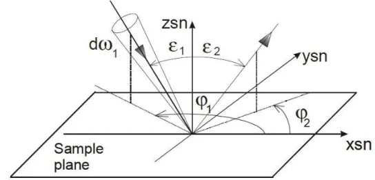
The measurements geometry for the calculation of q is shown in Figure 3.8. To specify each direction, incident or scattered, it is necessary a pair of angles (ε, φ). The polar angles ε1 and ε2 are
the angles between the optical axis of the incident beam and the surface normal; the azimuth angle φ can instead be utilised to indicate the difference between the azimuth plane of incidence defined by φ1 and the plane of view defined by φ2 (φ = φ2 - φ1).
Figure 3.8: Reference angular system for incident and reflected light beam.
The instrument is composed by the following elements: A fixed luminous source;
A detector (photometer or spectra-radiometer); A sample cradle rotator.
As a consequence, three axes which can have each orientation in the space, can specify the coordinates system used for measurements: the direction of the lighting beam, the view direction and the sample normal.
As shown in Figure 3.9, the light source hit the sample horizontally: The detector is installed on the horizontal plane containing it.
As shown in Figure 3.10 the detector can rotate around a vertical axis, which contains the centre of the cradle rotator setup supporting the sample that permits its orientation in any direction in the space. The cradle can also be lowered for permitting the measurement of the lighting beam luminance (or radiance) directly through the detector. The generality of the measurement system that means that it is possible to measure all geometrical configurations, is preserved if the sample normal can be rotate in any directions in the space. This requirement is satisfied only for the hemisphere facing the source, the one used for reflection measurements [3.4].
The sample is positioned in the centre of rotation O of a cradle rotator. This cradle (with a radius of 300 mm and a rotation range of 100°) is mounted on a rotating unit and on two optical benches (on one is installed the photometric detector). The optical benches have dimensions 300 mm x 1500 mm and rotate horizontally.
Figure 3.9: Gonio-photometer setup (horizontal plane).
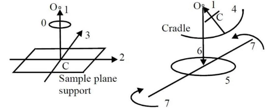
Figure 3.11 gives schematically a representation of the gonio-photometer movements: four linear (1, 2, 3, and 6) and four circular (0, 4, 5, and 7).
Figure 3.11: Linear (1, 2, 3, 6) and circular (0, 4, 5, 7) movements of gonio-photometer.
In particular:
The movement 1 shifts the sample along its normal (axis zsn in the sample reference of Figure 3.8): In order to obtain the coincidence between the sample surface height and the centre of cradle-rotator setup supporting it, the sample thickness has to be considered. The movements 2 and 3 shift the sample along two perpendicular axes on its plane (they
could coincide with axes xsn and ysn of Figure 3.8): these movements permit to analyse different zones of the sample.
The movement 6 permits to lift up and pull down the sample along the vertical: it is utilised only to commute between source (L1) and sample (L2) luminance / radiance measurements.
The movement 0 permits to rotate the sample around its normal.
The movement 4 is obtained by a guide that runs on the cradle: it permits each inclination between 0° and 100° of the sample normal respect to the horizontal plane.
The movement 5 rotates the entire system cradle-sample around a vertical axis passing through the rotation centre O of the system.
The movement 7 rotates horizontally the optical benches: on one of which is installed the detector.
From Figure 3.11 it can be observed that: if the central point of the sample analysed zone coincides with the centre of the cradle rotator O, this central point remains fixed while the guide run on the cradle (movement 4).
The linear and circular movements have respectively a mechanical precision of 0,01 mm and 0.01°. Globally it is possible to carry out radiometric / photometric measurements for any directions of incidence, any orientation of the reflection view axis (Figure 3.8) and almost all orientation of transmission viewing axis (Figure 3.2), with an uncertainty of 0.1°.
Once aligned the system by the movements 1, 2, 3, 6, it is possible to position the sample for each measurement configuration (ε1, φ1; ε2, φ2) by the other movements 0, 4, 5, 7.
The detector mounted on the gonio-photometer is CCD (Charge Couple Device) luminance meter. It is a suitable devices able to evaluate the luminance of an acquired scene using digital technology. One of the advantages in the use of the CCD detector is its linearity associated with the possibility of varying the exposure time. In this way the calibration (incident illuminance measurement) is performed with the same detector by pointing directly the source.
The measurement of the luminance / radiance coefficient q is performed according to the following algorithm.
Indicating with “D” the distance between the light source and the sample in O (the centre of cradle rotator) and with ε1 the incidence angle, considered as a constant, for all the elements ΔSbi
of the source (hypothesis certainly correct considering the small extension of this), the illuminance E in O can be written as:
∑
having indicated with Lbi the luminance of every element ΔSbi. The summation is extended to
the entire source surface.
If the luminance of the source is uniform (a necessary condition, following the traditional measurement methodologies for gonio-photometers), all luminances Lbi are constant and the
summation coincides with the luminance Lb of the source multiplied by its total area Sb. In this case
this requirement is not necessary because, by means of the CCD detector, all values Lbi can be
accurately measured.
In the context of material characterisations, the required accuracy is not comparable to that needed for the calibration samples. In this case, for practical reasons mainly related to the time of measurement, it is preferred to place the result of the summation equal to the average luminance of the source Lb multiplied by its total area Sb.
By introducing the geometric parameter G:
(
)
The value of q can be obtained with the following equation 4:
Knowing the measured luminance values of light source (Lb) and sample (LS).
Unfortunately, also this type of measurement is not simple because of the relation between Lb and LS that can exceed 4 orders of magnitude. The peculiar operation of the CCD detector
allows to solve this problem through different exposure times: in fact, the output signal is proportional to the product of the luminance for the integration time. In the gonio-photometer the integration time is defined by a specially designed rotating shutter. By doing this it is possible to carry out the two measures under conditions of linearity of the detector.
The final equation is:
having indicated with Tb the exposure time used to measure the light source luminance, with
TS the exposure time used to measure the sample luminance and with k a correction parameter
dependent on the readings of the CCD in the two measurement conditions.
3.5
Emissometer
The emissivity is the basic parameter to thermally characterise a material. It represent the capability of a body to emit the absorbed heat and it is a temperature function. The device proposed to measure the thermal emissivity is a Devices & Service emissometer, model AE 1, a very simple and cheap tool, based on the fact that the output quantity is a voltage value directly proportional to the emissivity value of the sample. It was made available by UTEE (Unità Tecnica Efficienza Energetica) of the ENEA Casaccia Research Centre.
It is capable of measuring the heat emission from a body in the wavelengths between 3 and 30 microns, and returns as output the broadband value in that band.