Chapter 3
REFERENCE PLANT AND ROD EJECTION ACCIDENT DESCRIPTION
3.1 Reference plant description 3.1.1 General lay-out
This study used as reference Nuclear Power Plant (NPP) the Kozloduy-6 NPP, a WWER-1000, model 320,which started operations in May 1991 [15]. It is a pressurized water reactor with a thermal nominal power (PNominal) of 3000 MW, equipped with 4 loop and 4 horizontal steam
generators. Each loop is also equipped with a Main Coolant Pump (MCP). The primary coolant operates at a pressure of 15.6 MPa with a medium flow of 17611 Kg/s; it exits from the core at a temperature that can reach the maximum value of 592 °K during operating conditions.
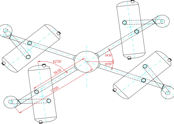
Fig. 3.1.1.1 - Primary circuit lay-out
The primary coolant transfers part of its energy to the secondary coolant in the orizzontal steam generators. Here steam is formed, dried and sent to turbine at a pressure of 6.28 MPa and a temperature of 551.5 °K. A brief description of the main components of the plant involved in this study is reported below.
Fig. 3.1.1.2 – Primary loop sketch
3.1.2 Reactor vessel and internals
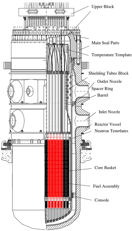
The reactor pressure vessel is the pressure boundary of the reactor core and high-pressure coolant. The detailed geometry of the reactor pressure vessel is presented on Figure 3.1.2.1
The lower part of the vessel consists of an elliptical flow distributor plate with perforations passing through the inner vessel. The perforations are circular holes 40 mm in diameter and 1344 holes are present (Figure 3.1.2.2). The curvature of the reactor shaft elliptic bottom is greater than the curvature of the reactor vessel elliptic bottom. This configuration allows for a significant amount of flow area to be present even during the most severe loss of coolant accident (LOCA) and high vessel temperatures. Thus, this increase in area was a way to try and guarantee that a significant part of the flow path will be available so that coolant will be able to reach the active section of the core during severe conditions. Once the coolant passes through the perforation of the inner vessel, the flow reaches the lower plenum, which is adjacent to the fuel support columns.
The fuel support columns are also perforated to allow the coolant to enter into the fuel assemblies themselves. The fuel support columns are welded to the inner vessel and welded together at the top such that no flow passes around the fuel support columns. The upper part of support columns has a hexagonal shape with a central circular opening for the bottom of the fuel assemblies. There are 163 fuel support columns since there is a one to one correspondence between the fuel support and the columns. The fuel support columns have an outside diameter 194 mm with a metal thickness of 12 mm. The perforations in the support column are ellipsoidal slits about 30 mm long (major axe) and 3 mm wide (minor axe). Each column along the height has 12 rows of slits. Every two adjacent rows are shifted in a chess layout. The distance between two adjacent slits in a row is 60 mm, thus every four adjacent slits form a rhomboid 30 mm wide. Primary coolant flows through the slits, upward through the supporting columns and into the fuel assemblies. The
perforations act as an orifice to distribute the flow. Another function of the slots is to prevent debris from entering the active fuel region and completely blocking off an assembly. Supporting columns also ensure that an even stress is applied to the elliptic bottom of the inner vessel while providing the support for the fuel.
Fig. 3.1.2.1 – Reactor vessel and internals
Upper Block
Main Seal Parts Temperature Templates
Shielding Tubes Block
Spacer Ring Barrel Outlet Nozzle Reactor Vessel Inlet Nozzle Neutron Templates Core Basket Fuel Assembly Console
The core barrel rests on a support ledge recessed in the upper part of the reactor pressure vessel immediately below the level where the upper head is bolted on. Outside of the upper part of the core barrel is the supporting ring. The core barrel is secured in place by the reactor pressure vessel head.
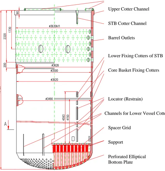
The top of the core barrel has an “o” ring around its circumference. When the head is bolted on, the “o” rings are elastically compressed between the head and the supporting ring of the core barrel to ensure a complete seal. The core barrel is shown on Figure 3.1.2.2.
Fig. 3.1.2.2 – Core barrel
Elastic Tube Element Upper Cotter Channel
STB Cotter Channel
Barrel Outlets
Lower Fixing Cotters of STB
Core Basket Fixing Cotters
Locator (Restrain)
Channels for Lower Vessel Cotters
Spacer Grid
Support
Perforated Elliptical Bottom Plate
On the upper part of the core are positioned the set of safety tubes, which have these several functions:
• to create a lattice for the correct position of the upper part of the fuel elements
• to avoid a vertical diplacement of the fuel elements
• to protect the actuators and control and safety systems from coolant flow effects The set of safety tubes incorporates the following:
• perforated bottom plate, which mounts fuel assemblies heads locking devices — fuel assemblies catchers and wherein the lower ends of safety tubes and intra-reactor monitoring ducts are fixed
• top plate, wherein the upper ends of safety tubes and output devices are fixed
• safety tubes, which are the main set of safety tubes part; these tubes are intended to protect control and safety system actuators and the larger part of intra-reactor monitoring ducts from coolant direct effects
• perforated shell, serving to improve the conditions of coolant flow equalization before the reactor outlet pipes, as well as to couple the top and bottom plates
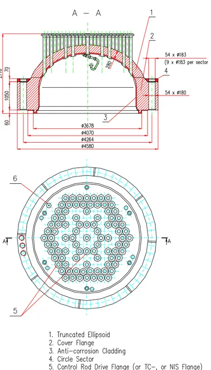
Fig. 3.1.2.3 – Set of Safety Tubes
Fig. 3.1.2.4 – A-A section from Fig. 3.1.2.3
In the set of safety tubes top lattice, provision is made for holes to cool the reactor closure and main joint sealing points. Set of safety tubes lower portion is mounted upon spring-loaded pins of the heads of fuel assemblies; the set of safety tubes upper portion is pre-compressed by the flange of upper block closure in the course of tightening the seal of the reactor.
Reactor cover assures the sealing of the pressure vessels, the entrances for the nuclear instrumentation sensor cables and by some nozzles, the connection of the CR drive mechanism pressure housing to the reactor vessel.
Fig. 3.1.2.5 – Reactor Cover
Cooling of the external parts of the cover is realized by air forced by some fans.
3.1.3 Core description
In Table 3.1.3.1 are reported the main geometrical and physical data for the core. The reactor core is composed by 163 hexagonal fuel assemblies with 235U enrichment between 2.0 and 3.3 %. Every fuel assembly is composed by 330 fuel rods and a water rod arranged with a pitch of 12,76 mm in a triangular lattice. Sixty-one of these fuel assemblies are composed by 312 fuel rods, a water rod and 18 guide tubes to allow the insertion of a CR cluster. Every fuel rod is constrained in the correct position by the presence of 15 spacer grids.
Table 3.1.3.1 – WWER 1000 Core Geometric and Physical Data
Parameter Value
Equivalent Diameter, m 3.120
Active Height, m 3.55
Volume, m3 27
Moderator-fuel area ratio 2
Operating pressure, MPa 15.6
inlet 562
Average coolant temperature, °K
outlet 593
Medium coolant flow, Kg/s 17611
Core pressure drops, MPa 0.18
Reactor pressure drops, MPa 0.4
Fuel weight, Kg 75000 235 U enrichment, % 3.3 – 2.0 inlet 9.8 Coolant speed, m/s outlet 11
Average core power density, KW / l 111
Fuel Assembly number 163
CR cluster number 61
A clad of Zr-Nb alloy, with an outer diameter of 9.1 mm and a thickness of 0.65 mm, encases the fuel pins.A detailed geometric description of a fuel assembly and of its components is shown in Table 3.1.3.1 and in Figure 3.1.3.1. Physical properties of fuel as function of temperature are instead reported in Table 3.1.3.
Table 3.1.3.2 – FA geometric data
Parameter Value
Pellet diameter, mm 7.53
Clad diameter (outside), mm 9.1
Clad wall thickness, mm 0.65
Fuel rod total length, mm 3837
Fuel rod active length (hot state), mm 3550
Fuel rod pitch, mm 12.76
Fuel rod grid Triangular
Number of guide tubes 18
Guide tube diameter (outside), mm 12.6 Guide tube diameter (inside), mm 11.0
Number of fuel pins 312
Number of water rods/assembly 1
Water rod diameter (outside), mm 11.2 Water rod diameter (inside), mm 9.6
FA wrench size, mm 234
Fig. 3.1.3.1 – Fuel assembly lay-out
Table 3.1.3.3 – Fuel properties [4]
Parameter Value T, 0K 300 500 700 900 1100 1300 1500 λ, W/m0K 8.15 6.7 5.4 4.4 3.75 3.25 2.80 cp, J/kg0K 270 287 302 310 314 319 320 ρ, kg/m3 10400 ÷ 10800 cv, kJ/m30K 2862.0 3042.2 3201.2 3286 3328.4 3381.4 3392
Parameter Value T, 0K 1700 1900 2100 2300 2500 2700 2900 λ, W/m0K 2.50 2.40 2.42 2.44 2.5 2.65 3.0 cp, J/kg0K 328 340 364 390 426 470 520 ρ, kg/m3 10400 ÷ 10800 cv, kJ/m30K 3476.8 3604 3858.4 4134 4515.6 4982 5512
Table 3.1.3.4 – Cladding properties [4]
Parameter Value t, °C 20 100 200 300 400 500 600 700 800 T, 0K 293.15 373.15 473.15 573.15 673.15 773.15 873.15 973.15 1073.15 λ, W/m0K 17.2 18.0 19.3 20.1 20.5 20.9 21.8 22.9 cp, J/kg0K 280 301 322 343 368 398 448 420 cv, kJ/m30K 1834 1972 2109.1 2246.7 2410.4 2606.9 2934.4 2751 Parameter Value t, °C 900 1000 1100 1200 1300 1400 1500 T, K 1173.15 1273.15 1373.15 1473.15 1573.15 1673.15 1773.15 λ, W/m0K 27.8 29.0 30.1 31.2 32.3 33.4 cp, J/kg0K 380 290 cv, kJ/m30K 2489 1899.5
Table 3.1.3.5 – Properties of fuel rod gap [4]
Parameter Value T, °K 273.15 373.15 473.15 573.15 673.15 873.15 1073.15 λ, W/(m 0K) 0.145 0.181 0.214 0.246 0.279 0.334 0.387 cp, J/(kg 0K) 5193.0 γ, kg/m3 3.50 2.59 2.04 1.69 1.44 1.11 0.90 cv*10-3, J/ (m30K) 18.176 13.450 10.594 8.776 7.478 5.764 4.674
3.1.4 Control System description
In the Figure 3.1.4 is shown the Kozloduy NPP control rod banks arrangement. The are 61 CRs cluster grouped in 10 banks, which can have safety or regulation purposes. Every bank, except bank 5 and 6, is composed by 6 CRs. Strong absorber (B4C) are present along CRs full length. Only the
CRs of bank 5, which have the function to damp the Xenon oscillations, present absorber along their lower half. The “arms” of the cluster (see Figure 2.1.4 for a geometric description) are placed inside the guide tubes of a Control Assembly (CA) along all its length (371 cm) when the CR is inserted.
Fig. 3.1.4.1 - Kozloduy - 6 NPP CR banks disposition 1 2 3 4 5 6 7 8 9 IV 10 11 IX 12 16 17 III 18 19 VIII 20 II 21 I 13 III 14 15 22 VII 23 24 IV 25 61 26 27 28 VII 29 30 31 VI 32 33 34 VIII 35 36 37 38 IX 39 I 40 41 X 42 43 44 X 45 46 II 47 IX 48 49 50 51 II 52 V 53 54 55 VI 56 57 58 V 59 I 60 62 63 IV 64 VIII 65 66 67 VI 68 69 70 VI 71 72 73 VII 74 III 75 101 IV 102 76 77 78 79 X 80 81 82 V 83 84 85 X 86 87 89 90 III 91 VII 92 93 94 VI 95 96 97 VI 98 99 100 VIII 115 103 104 105 I 106 VI 107 108 109 VI 110 111 112 VI 113 II 114 116 117 IX 118 II 119 120 X 121 122 123 X 124 125 I 126 IX 127 128 129 130 VIII 131 132 133 V 134 135 136 VII 137 138 139 140 IV 141 142 VII 143 I 144 II 145 VIII 146 147 III 148 149 150 151 III 152 153 IX 154 155 IV 156 157 158 159 160 161 162 163 88
I
II
III
IV
20°30’ 34°30’ 34°30’ 20°30’ MCP 1 MCP 2 MCP 3 MCP 4 A BFA with Control Rod A – FA number
B – Control Rod Group number
I, II, III, IV
– Reactor Vessel and Core AxesBank No rods Purpose
I 6 Safety II 6 Safety III 6 Safety IV 6 Safety V 4 APSR (*) VI 9 Safety VII 6 Safety VIII 6 Safety IX 6 Safety X 6 Regulating
3.2 Description of Rod Ejection Accident
The Rod Ejection Accident (REA) is defined as an assumed failure of the control rod mechanism pressure housing such that the reactor coolant system would eject the control rod and drive the shaft to the fully withdrawn position. It is a postulated accident, that is a deviation from the normal operations of the plant of safety concern with a probability to happen less than 10-2 /year.
The consequences of this accident is a rapid reactivity insertion together with a power burst and an adverse core power distribution. If this event were to happen, a fuel rod thermal transient wich could cause DNB may occur together with limited fuel damage. The amount of fuel damage that can result form such an accident will be governed mainly by the worth of the ejected rod and the power distribution attained with remaining control rod pattern. Therefore the fuel suffers a rapid overheating that can lead to the partial melting of the pelletts and to their fragmentation. The DNB that could happen can also lead to a clad rupture with consequently fuel dispersal into the coolant. The transient is terminated by the Doppler reactivity effect of the increased fuel temperature, by the negative moderator temperature and eventually by a reactor scram caused by high neutron flux signal.
Figure 3.2.1 – REA schematization
The break in the pressure housing mechanism create also a hole in the top of the reactor vessel, producing a small break loss of coolant accident (SBLOCA). This scenario would initiate a depressurizzation of the reactor coolant system (RCS). The effects of this scenario are studied in the SBLOCA analyses; here, it is assumed that the hole is plugged by the ejected rod. As a consequences, a pressure increase occurs in the RCS until pressure-relieving devices act to reduce it. Therefore, this event could challenge the faulted condition stress limits of the RCS.
Feature in the design preclude the possibility of a REA, or limit the consequences of the event if it were to occur. These include a thorough quality control program during assembly, and a nuclear design which lessens the potential ejected worth of the control rods. The consequences of
this accident are limited by the presence of control rod insertion limits and the limited reactivity worth of the individual control rods. The control rod insertion limits, which vary as function of power level, are present to limit the reactivity worth of the rod inserted in the core when the core is critical. In addition on ensuring that adequate shutdown margin is available throughout the cycle at all power levels, the rod insertion limits also constrain the amount of reactivity associated with the ejection of a control ros as well as the resulting core peaking factors following the ejection. Typically, the plant operates with the rods well above the insertion limits. Therefore, only a minor reactivity excursion would be expected following a REA. However, the plant may occasionally operate with control rods near the insertion limits after changes in plant power level or during load follow operation.
For conservatism, in the nuclear design analysis, as in this work, it is assumed that the control rods are at the insertion limits in order to maximize the reactivity insertion.
3.3 Main plant parameters
Two state of the plant were analyzed in this work: the Hot Full Power (HFP) and the Hot Zero Power (HZP), to bound operations from zero to full power. Furthermore the first state implies a transient to a fuel that is at high temperature as long as the second state could lead to a severe transient for the clad because the minor coolant flow associated with fewer pump in operation.
The HZP and HFP with the nuclear fuel at the BOL and at the EOC were analyzed. The control rod was always assumed to be ejected in 0.1 seconds from the fully inserted to the completely withdrawn position. The scram delay signal, also according to [4], was assumed to be 0.3 seconds and the time for the complete insertion of all the CRs was assumed to be 3.6 seconds. In table 2 are summarized the main parameters imposed for the defining of the plant status.
Table 3.3.1 - Main plant parameters for the HZP and the HFP
Hot Zero Power Hot Full Power
Core Power 0.1 % PNominal 100 % PNominal
PRZ pressure 15.6 MPa 15.6 MPa
Pumps in operation 4 4
Boron Concentration (ppm) 1208(BOC) 5.0 (EOC)
1208 (BOC) 5.0 (EOC)
Core inlet coolant temperature (°K) 550 550
Fuel average temperature (°K) 552 977
CRs group positions I to III A.R.O.(*) IV 57% withdrawn V A.R.O. VI to X A.R.I.(**) I to X A.R.O. Transient 1 CR ejected in 0.1 seconds Scram set-point : 40% PNominal 1 CR ejected in 0.1 seconds Scram set-point : 120% PNominal
Scram delay signal (s) 0.3
Scram time (s) 3.6
(*) All Rods Out (**) All Rods In
3.4 Control rods worth spectrum
The calculations of the CR worth were executed using the PARCS code in a stand-alone mode. Note that for every transient executed here described, it was ejected only one of the six CR that formed every bank. Detailed information about core modelling and nodalization used are reported in Chapter 3 of this work. Two ways of calculation were followed:
• in the first way, starting with CR banks positions described in Table 3.3.1, there were executed a series of transients, changing every time the ejection of a control rod previously fully inserted. At the end of the transients calculation, it was extracted by the data the maximum reactivity insertion and therefore, the control rod worth
• in the second way (following the definition of CR worth given in [16], it was realized a series of steady state calculations of the keffective (k1) assuming the CR banks positions
described in Table 3.3.1 and the control rod that has to be ejected fully inserted; then it was performed a steady state calculation of the keffective (k2) with this control rod completely
withdrawn. The reactivity insertion was therefore calculated by the formula :
β
ρ
($)
*
1
2 1 2k
k
k
−
=
In this last way, it was clearly ignored the Doppler effect and the flux redistribution in the calculation. It was executed only for obtain a kind of validation of the first way of calculation. As can be seen in the Table 3.4.1-4, the values are roughly the same.
Table 3.4.1 – CR worth spectrum for the HZP - EOC
CR ejected bank number CR worth – 1st way of calculation ($) CR worth – 2nd way of calculation ($)* 6 0.232 0.273 7 1.337 1.573 8 1.235 1.45 9 1.338 1.575 10 0.255 0.30 (*) b : 5.5*10-3
Table 3.4.2 – CR worth spectrum for the HZP – BOL
CR ejected bank number CR worth – 1st way of calculation ($) CR worth – 2nd way of calculation ($)* 6 0.0806 0.0949 7 1.024 1.205 8 0.807 0.95 9 1.167 1.373 10 0.0128 0.0151 (*) b: 7.268*10-3
Table 3.4.3 – CR worth spectrum – HFP - BOL CR ejected bank number CR worth – 1st way of calculation ($) CR worth – 2nd way of calculation ($)* 1 0.1828 0.1930 2 0.1957 0.2067 3 0.1262 0.1333 4 0.1108 0.1170 5 0.1545 0.1631 5_center 0.1608 0.1698 6 0.1609 0.1699 7 0.1469 0.1552 8 0.1707 0.1803 9 0.1191 0.1258 10 0.1602 0.1692
Table 3.4.4 – CR worth spectrum – HFP – EOC CR ejected bank number CR worth – 1st way of calculation ($) CR worth – 2nd way of calculation ($)* 1 0.2113 0.2442 2 0.2263 0.2615 3 0.1459 0.1686 4 0.1281 0.1480 5 0.1786 0.2064 5_center 0.1859 0.2148 6 0.1860 0.2149 7 0.1699 0.1963 8 0.1974 0.2281 9 0.1377 0.1591 10 0.1852 0.2140
As can be seen by the previous tables, the CR with the maximum worth for the HZP is one of the CR of the bank number 9; for the HFP is one of the CR of the bank number 2. Thus, for every transient performed later, it was assumed a REA caused only by these two rod assembly failure.


![Table 3.1.3.5 – Properties of fuel rod gap [4]](https://thumb-eu.123doks.com/thumbv2/123dokorg/5664709.71419/10.892.55.844.346.739/table-properties-fuel-rod-gap.webp)
