Chapter 3 Handling of microproducts within the microfactory
Chapter 3
Handling of microproducts within the microfactory
3.1 Introduction
As seen in Chapter 2, the automatic handling of microcomponents is a key task within the assembly microfactory. The main handling operations are:
• Sorting & Sieving • Grasping & Releasing • Feeding & Positioning • Inserting
• Orienting
These different tasks are carried out by means of different handling devices such as microfeeders to transport, locate and orient microparts, microgrippers to grasp and release components, microrobots to support and move microgrippers and micropositioners to carry microparts. Other devices as sorters and sieves are required to organize in preset locations randomly positioned microparts.
It is important to highlight that in this classification are considered as feeders the systems able to directly move microparts, while devices as carriers that are used to carry microcomponents are considered as micropositioners.
In this Chapter, some of these handling devices are analyzed by showing their state of the art. In § 3.2.1 are considered microparts feeders and positioners with particular focus on electrostatic feeders. In § 3.2.2 are treated grasping and releasing devices, in § 3.2.3 microrobots and manipulators and, finally, in § 3.2.4 are considered sorters and sieves.
3.2 State of the art in the handling of microparts
3.2.1 Strategies for transporting, positioning and orienting
microparts
In the microfactory concept, automatic microfeeders are needed to transport parts to the assembly stations and to move them within the assembly workspace. These devices have to locate microparts in the correct position along the required orientation.
Since in the microdomain surface forces equal or overcome gravity (please refer to § 2.1.1), traditional systems are not suitable and so innovative handling strategies have been developed. Most of them take advantage from the very little mass of the handled components: forces usually irrelevant in the macrodomain become adequate to handle parts of a few milligrams.
These novel handling strategies can be distinguished in two macro categories: contact and no contact handling as shown in Table 1.
Microhandling devices for the assembly of Hybrid Microproducts
Contact handling (H.C)
Principle Actuation Description
Pushing tool Piezo [1][2][3] Use a pushing tool to move and rotate microobjects
Friction Suction + Piezo [4] Use the friction caused by suction force to move objects
Thermal [6][7][8]
Use thermal expansion of polyimide joints to achieve motion
Electrostatic [9][10] Use electrostatic force for the activation of cilia
Magnetic [11] Use magnetic force for the activation of cilia Cilia
Coordinated motion of array of cilia to move microobjects [5][6]
Piezo [10][12] Use piezoelectric to actuate cilia
No Contact handling(H.N.C)
Principle Actuation Description
Air flow Air [13][14] Use air flow to move microobjects
AC fields [15][16][17]
[18][19]
Use AC electric field to move microobjects
Electric DC fields [20][21][22]
[23][24][25][26]
Use DC electric field to move microobjects
Standing waves: Small parts are held in the pressure node of standing waves between an ultrasonic source and a reflector Ultrasonic
waves Near field (or squeeze film): The reflector of the standing wave levitation is the levitated part itself. It allows the transporting of heavy objects [27]
Ultrasonic
[28][29]
Use of high intensity ultrasounds (f>20 KHz) to apply pressure forces on the microobjects and to lift them. The transportation of parts can be obtained by the motion of sonodrome or varying its electronic parameters [29]
Laser beam Laser [30]
Use Focused Laser beam to move microobjects. Thanks to the beam reflection and refraction, an axial force pushes a component forwards in the direction of the beam
Vibration Vibrations [31][32][33] Use surface vibrations to move microobjects
Table 1: Contact and no contact transporting strategies.
Contact strategies
The innovative contact strategies make use of different approaches to move and orient microobjects:
• pushing tool
• active friction force field
Chapter 3 Handling of microproducts within the microfactory
The pushing tool method exploits one or more tools with dimensions smaller [1] or comparable [2] to those of the object to be moved and oriented: this tool can be a piezoresistive AFM cantilever [1], a stainless tip sheet piezo actuated [2], a microslider actuated by piezoelectric vibration [3].
The active friction force field approach has been employed by Sin and Others [4] by using an array of pneumatic nozzles and piezoelectric actuators. The pneumatic nozzles make the object adhere to a plane by suction, then the plane, by means of piezo actuators, moves. Since the friction caused by suction force overtakes the one against the motion, the object moves in the same direction of the platform.
In the coordinated motion of array of microactuators, the key idea is to organize the simple motion of microactuators (cilia) to carry and position an object by means of the friction generated among cilia and objects. These cilia (so called in analogy to their biological counterparts in the human respiratory tracks) can be actuated with different principles such as thermal [6][7][8], electrostatic [9][10], magnetic [11] and piezoelectric one [12].
No Contact strategies
Concerning the no contact strategies, they employ various actuation principles: • electric fields
• magnetic fields • air flow
• ultrasonic waves • focused laser beam • surface vibrations • Bernoulli levitation
With regard to air flow manipulation, the lift and motion of microparts is obtained by the coordination of several air flows [13][14]. The key idea is to realize an array of microactuators having two or more nozzles electrostatic driven, that can be opened or closed permitting the air to flow. Konishi and Fujita [13] levitated and carried an object by controlling air flows from many actuators. Each actuator has two on-off electrostatic driven nozzles. Turitto and Others [14] proposed a feeder based on contactless pneumatic distributed manipulation: an array of microactuators having four nozzles allows the part to be suspended and moved by air flows. The motion and the orientation of parts are obtained by the coordination of the different nozzles, each of them actuated by electrostatic force.
The electrostatic manipulation, deeply considered in the following paragraph, exploits the principle that bodies in an electric field are subjected to forces arising either from electrophoresis (direct attraction of a charge in an electric field) or dielectrophoresis (polarization of the matter and its subsequent tendency to move into regions of different strength field) or from a mixture of both [20]. Both AC [15][16][17][18][19] and DC [20] [22][21][23][24][25][26] fields are used in literature to move microobjects.
Microhandling devices for the assembly of Hybrid Microproducts
In the magnetic force handling, microobjects are levitated and/or moved by means of magnetic fields.
Ultrasonic waves handling makes use of high intensity ultrasound (f>20 KHz) to apply
pressure forces on microobjects and to lift them. The transportation of parts can be obtained by the motion of sonodrome or varying its electronic parameters [29]. A further classification can be done between Standing waves and Near field (or squeeze film) [28]. In “standing waves” approach, small parts are held in the pressure node of standing waves between an ultrasonic source and a reflector. In the “near field” technique, the reflector of the standing wave levitation is the levitated part itself. Thus, it allows the transport of heavy objects [27].
In the focused laser beam manipulation [30], thanks to the beam reflection and refraction, an axial force pushes a component forwards in the direction of the beam.
Similar to traditional vibration feeders, it is possible to feed parts by means of surface
vibration. Vorstenbosch and Others [31] made use of a vibration tooling plate to separate
and orient parts with dimensions between 0.5 and 5 mm.
The above mentioned non contact strategies show good performance in terms of reducing sticking effects and avoiding the damage of the small and fragile manipulated parts. The main advantages of no contact handling strategies are:
• surface forces are reduced or completely neglected;
• fragile and sensitive parts can be manipulated without risk of damage and contamination (these features are very important in case of delicate parts such as biomedical and optical devices);
• there are no problems in manipulating soft parts.
The electrostatic transporting and positioning of microparts
Electrostatic handling has some advantages in comparison with other no contact strategies:
• there is no residual effects on manipulated objects;
• both metallic and dielectric components in a wide dimension range (from a few µm to some mm) can be handled;
• electrostatic fields are quite simple to be generated and controlled in comparison to other methods (e.g. air flows).
In feeding, AC and DC electrostatic fields have been used to manipulate and position microparts. An important issue mentioned in literature with regard to the electrostatic feeding, is the need to eliminate or reduce adhesion forces [20]. In some AC electric feeders microparts are lifted by means of electric force and then adhesion forces are completely removed [15]. In DC feeders, authors reduce them by using air flow [20] or vibration [21][22][24][25].
With regard to AC electric fields, Moesner and Higuchy [15] lifted and conveyed metallic and plastic spheres with a diameter up to 400 µm with a non uniform electric traveling
Chapter 3 Handling of microproducts within the microfactory
field: particles become charged through the application of three or six phase AC voltage to parallel electrodes and move perpendicular to them. A similar approach have been used in [16][17] by using AC traveling field. Gan Mor and Law [16] transported charged particulates with a diameter of 15 µm by means of a three phase AC electric field. This electric field is imposed by a series of parallel electrodes. Deasai and Others [17] realized a MEMS feeder that consists of 3 phase electrode arrays covered by insulators. This system, supplied with 200 Volt, is capable to transport particles with a diameter of 5-10 µm in air. Arai and Others [18] have developed a bio aligner able to control the position and the orientation of little objects (they made tests with glass spheres with a diameter of 100 µm) by means of dielectrophoresis forces arising among electrodes supplied with AC voltage. Fuhr and Others [19] induced the linear motion of dielectric spheres and living cells with a diameter of 5-100 µm by using traveling electric field. An AC voltage with frequency of a few MHz is applied to a linear pattern of electrodes: the resulting electrostatic forces levitate the particles and move them laterally in the direction of the traveling field.
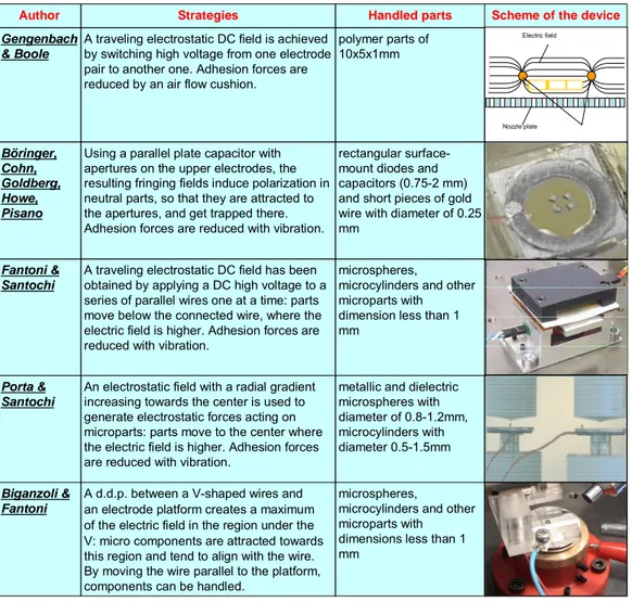
Concerning DC electric field, Gengenbach and Boole [20] have developed an electrostatic feeder able to convey polymer parts of 10x5x1mm: a traveling electrostatic field is achieved by switching high voltage from one electrode pair to another one. Since their conveyor lifts objects thanks to the air flow instead of electrostatic forces, thus it permits to handle big parts. Böhringer and Others [21] positioned and aligned surface-mount diodes and capacitors with rectangular dimensions between 0.75 mm and 2 mm and short pieces of gold wire of 0.25 mm of diameter by using a parallel plate capacitor with apertures on the upper electrodes: the resulting fringing fields induce polarization in neutral parts, so that they are attracted to the apertures, and get trapped there. Fantoni and Santochi [22] used the concept of a moving capacitor between a platform and a series of parallel wires supplied one at a time: microspheres, microcylinders and other microparts with dimensions less than 1 mm move below the connected wire where the electric field is higher. This electrostatic feeder is able to orient and transport microcomponents along a straight line. Porta and Santochi [24] realized an electrostatic system able to center microcomponents. The device makes use of an electrostatic field with a radial gradient increasing towards the center to generate electrostatic forces acting on microparts and also utilizes a vibrating platform to reduce adhesion forces. The good choice of the electrostatic field and of the vibration amplitude and frequency allows the correct centering of microcomponents. Biganzoli e Fantoni [25] developed a device able to manipulate on a plane microbjects with dimensions in the range of 0.5-1 mm. A d.d.p. is applied between a V-shaped wire and an electrode platform: this electric configuration creates a maximum of the electric field under the tip of V. So, micro components are attracted toward this zone and then tend to align with the wire. By moving the wire parallel to the platform, components can be handled. Kikuya and Others [26] coated optical fibers with a thin metal film and aligned them within a “V” groove with electrodes on the two slopes of the groove by applying DC voltage between the fiber and both the electrodes. Controlling the voltage of the two electrodes, electrostatic forces make the fiber exactly aligned inside the groove.
Microhandling devices for the assembly of Hybrid Microproducts
Table 2 summarizes the DC electric field handling strategies and the features of the manipulated objects.
metallic and dielectric microspheres with diameter of 0.8-1.2mm, microcylinders with diameter 0.5-1.5mm An electrostatic field with a radial gradient
increasing towards the center is used to generate electrostatic forces acting on microparts: parts move to the center where the electric field is higher. Adhesion forces are reduced with vibration.
Porta & Santochi
microspheres,
microcylinders and other microparts with dimensions less than 1 mm
microspheres,
microcylinders and other microparts with dimension less than 1 mm
rectangular surface-mount diodes and capacitors (0.75-2 mm) and short pieces of gold wire with diameter of 0.25 mm
polymer parts of 10x5x1mm
Handled parts
A traveling electrostatic DC field has been obtained by applying a DC high voltage to a series of parallel wires one at a time: parts move below the connected wire, where the electric field is higher. Adhesion forces are reduced with vibration.
Fantoni & Santochi
A d.d.p. between a V-shaped wires and an electrode platform creates a maximum of the electric field in the region under the V: micro components are attracted towards this region and tend to align with the wire. By moving the wire parallel to the platform, components can be handled.
Biganzoli & Fantoni
Using a parallel plate capacitor with apertures on the upper electrodes, the resulting fringing fields induce polarization in neutral parts, so that they are attracted to the apertures, and get trapped there. Adhesion forces are reduced with vibration.
Böringer, Cohn, Goldberg, Howe, Pisano
A traveling electrostatic DC field is achieved by switching high voltage from one electrode pair to another one. Adhesion forces are reduced by an air flow cushion.
Gengenbach & Boole
Scheme of the device Strategies
Author
Electric field
Nozzle plate
Table 2: DC electric field handling strategies.
3.2.2 Strategies for grasping and releasing microparts
In the microfactory, grippers are required to carry out assembly tasks, to handle components within assembly stations, to load pallets moving throughout the assembly workspace. The grippers have to pick microparts up and release them with the correct orientation in the preset place with high accuracy. Furthermore, they have to do that without damaging or contaminating the parts they handle.
Chapter 3 Handling of microproducts within the microfactory
Many strategies have been developed for grasping microparts as shown in [34]. Some microgrippers configurations are downscaled from macro [35][36], while others take advantage, thanks to the very little dimension and mass of handled microparts, of surface forces or other effects for grasping components.
Principle Description
Friction
Objects are grasped by the friction between the fingers and the part. The opening/closing of the fingers is obtained by electrostatic [37][38], piezoelectric [39][40][41][42[43], shape memory alloy [44][45][46][48], magnetic [48] or pneumatic actuators [49].
Suction Objects are grasped by means of air suction [50][51][52].
Van der Waals Objects are picked up by van der Waals forces [53].
Cryogenic Objects are picked up by adhesion forces got freezing a little
volume of liquid [54].
Sound pressure Parts are levitated by ultrasonic radiation pressure [55][56].
Magnetic Parts are grasped by means of magnetic force.
Electrostatic Parts are grasped by means of electrostatic force [57][58]
[59][60][61].
Surface tension Use capillary forces to grasp microcomponents [62][63][64].
Optical pressure
A radial gradient force traps the component in the center of a beam when the component refractive index is higher than that of the surrounding medium [30][65].
Bernoulli
Due to the high pressure supply, air radially flows between the gripper and the component. The high velocity induces a dynamic pressure decrease (Bernoulli effect) leading an upwards attracting force on the component.
Table 3: Grasping strategies (adapted from [34]).
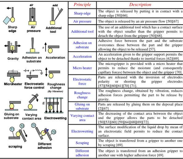
Conversely to the macroworld, in the microdomain the main problem is the releasing phase. Actually the gravity, usually used in traditional assembly to release components, is often less important than adhesion forces. Hence, components tend to remain stuck to the gripper, creating the need for the development of innovative releasing strategies. Table 4 shows the solution adopted in literature to allow the releasing of microparts.
Microhandling devices for the assembly of Hybrid Microproducts
Principle Description
Sharp edge The object is released by putting it in contact with a
sharp edge [50][66].
Air pressure The object is released by an air pressure flow [50][67] 1 Additional tool
The use of an additional tool which has a contact surface with the object smaller than the gripper permits to detach the object from the gripper [50][68].
Adhesion on substrate
Adhesive force between the part and the substrate overcomes those between the part and the gripper allowing the object to be released [57].
Acceleration An acceleration given to the gripper support permits the
object to be detached thanks to inertial forces [62][69].
Micro heater
The microgripper is provided with a micro heater that permits to reduce the moisture (and consequently capillary forces) between the object and the gripper [70].
Electrostatic force
Parts are released with the inversion of electrodes polarity or shorting the gripper electrodes [57][58][60][61][70] [71].
Roughness change
The roughness change, obtained by vibration, reduces adhesion forces permitting the part to be release by gravity.
Gluing on substrate
Parts are released by gluing them on the deposal place [2][67] .
Varying contact area
The decreasing of the contact area between the object and the gripper allows the parts to be detached [50][53][60] [59][64][68][69][72].
Electrowetting
The surface modification of the liquid drop by mean of an electrostatic field permits to reduce the contact surface.
Scraping The object is transferred from a gripper to another one
by scraping [69].
Different adhesion
The object is transferred from an adhesion gripper to another one with higher adhesion force [69].
Table 4: Releasing strategies.
For parts grasped by means of surface forces, general consideration could be done on microgrippers’ shape, material and roughness to limit the contact area and, consequently, to make simpler the releasing of microparts. In order to limit the effect of surface forces, it is important to pay attention to various aspects:
• fingers’ shape: spherical shape rather than a flat one;
• fingers’ material: hard materials that do not modify their shape during contact rather than rubber or plastic;
• fingers’ roughness: rough fingers rather than smooth ones.
In order to make reliable grippers able to pick and place microparts, often a grasping approach is coupled with one or more releasing strategies. Table 5 (inspired by [73])
Sharp edge
air
Air
pressure Additionaltool
add.
g
Gravity Adhesionon substrate
Micro heater Electrostatic force control Roughness change a Acceleration Gluing on substrate Electrowetting E Varying contact area
scraping adhesionDifferent T1 T2 T1 T2 edge air Air
pressure Additionaltool
add.
g
Micro heater Electrostatic force control
Electrowetting
E
scraping adhesionDifferent T1
T2 T1
T2
Chapter 3 Handling of microproducts within the microfactory
shows how grasping methods have been related to releasing strategy in grippers developed in literature. Grasping Principles Friction/ Jaw M agnetic Ice Van der Waals Electrostatic Adhesive f o rces (general) Adhesive ( liquid) Suction
Pressure by an acoustic sour
ce Pr essur e gener ated by a laser beam
Placing on adhesive substrate [57] Gluing the part in the right
place [2][67]
Greater adhesion [69] By positive mechanical
engagement [67] [74] Small puff of gas (blow
away) [67] [50] Mechanical release with
needle [67] Destruction of the gripper
mechanism
[54] [75]
Vibration of the gripper [76] [62] Dynamical effect [69] [62] Component against an edge [66] [50]
Auxiliary tool [50] [68] [50] Decrease the contact surface
(Rolling, varying area etc. ) [72]
[53] [60][59] [68][69] [64] [50] Electrostatic repulsion [70] [57][58] [60][61] Scraping off [69] Pressure generation by
thermal variation into microholes
[77] Roughness variation [70] Thermal control of surface tensions due to air humidity [70]
Relea
sing
Princip
les
Contactless handling [55][56] [30][65]
Table 5: Releasing strategies related to grasping strategies (adapted from [73]).
Since objects that differ in terms of material, shape, dimension etc. require different kinds of grippers, another issue considered in literature is the possibility to have many grippers available at the same time. The approaches used to fulfil this topic are:
Microhandling devices for the assembly of Hybrid Microproducts
• Gripper changing system
• Revolving turret with different kinds of grippers
In the first approach, different kinds of fingers can be mounted on the same support and used with the same actuators. Clevy and Others [43] made different mechanical end-effectors with two fingers that are fixed and released on the tips of the microgrippers actuators by means of thermal glue. Each gripper is characterized by a finger shape, a gap between fingers and an opening/closing capability. By changing the end-effectors, a wide range of microobjects can be manipulated. Driesen and Others [78] equipped robots with a tool changer in order to increase their functionality and flexibility. The end effectors are adhesion grippers positioned on the tip of a bender piezo actuated. Also in this case, the actuator of the various grippers remains the same.
In the revolving turret approach, various end-effectors are available on the same support and can be selected by the rotation of the turret. A revolver tool changer with six tool positions has been developed within the Microassembly system developed at Karlsruhe Research center [79]. This revolver permits to select the most suitable gripper-tool on the basis of the microassembly task to be carried out.
3.2.3 Strategies for microrobot & micromanipulator
Other significant elements belonging to the microfactory are microrobots and micropositioners. As mentioned in § 3.1 microrobots are systems that support grippers or other end-effectors, while micropositioners are devices (as carriers) that carry and move microparts throughout the workspace. These two kinds of devices are treated at the same time because they usually have similar design and they make use of the same principles for the motion and/or for the actuation.
Like in traditional assembly, the features of microrobots and micropositioners in terms of DOF, versatility, and dexterity depend on the microassembly task. However (as mentioned in § 2.1.2) the precision accuracy required in microassembly is generally lower than 10µm and it can reach values lower than 1 µm. So, microrobots to be used in microassembly tasks have to get these precision capabilities [80].
As shown in Table 6 (adapted from [46] and [80]), a rough classification of precision robots suitable to be used in microassembly can be done by taking into account their structure and design approach. On the basis of their structure [80] the types of microrobot are serial, parallel, hybrid, while considering the design approach [46] the micromanipulators can be realized with a top-down approach or a bottom-up one. In the top down approach, the performance of conventional robots are increased by modifying their existing structures, whereas in the bottom-up conception new robotic systems are specially developed for microassembly tasks [81]. Some microrobots shown in Table 6 are commercially available (c), while others are developed by research institutes (r).
Chapter 3 Handling of microproducts within the microfactory
Design approach
Top-down Bottom-Up
Cartesian
• Sysmelec Autoplace 411 [82] (c) • SPI Precision robots [83] (c) • Feinmess MP series [84] (c)
• MW3R/L Somapatch [89] (c)
• Robot of TOMI project [90] (r)
Serial Scara • Yamaha YK 120-150X [85] (c) • Bosch Turboscara SR6 [86] (c) • Mitsubishi Melfa RH-X [87] (c) • Epson E2C [88] (c) Hy brid
• Parallel hybrid robot [80] (r)
• Kleindeik MM3A [91] (c) • Nanomanip Klocke [92] (c) • Exfo PCS 4100 [93] (c) • NewPort: MRSI [94] (c) Planar • IWF Micabo –f [46] • IWF Micabo f2 [104][105](r) • Mitsubishi RP-series [95] (c) Structure Ty pe Parallel
Volumetric • IWF triglide • IWF Micabo –h [96] [97](r) (r)
Table 6: Classification of precision assembly robots (adapted from [46] and [80]).
In the top-down approach standard robots (e.g. little SCARA) are equipped with extra redundant axes of high resolution, additional sensors, special interface between the robot and the end-effector able to improve the manipulator functionality and precision [98]. This additional equipment give standard robots very good precision performance without losing the wide workspace they own [99]. The main drawbacks are that standard roots are very expensive (many thousands Euros) [80] and they have a high energy and space consumption in relation to microcomponents to be handled and assembled. So that their size make them not suitable to be inserted in little clean rooms where often the assembly takes place.
In the bottom-up approach, the improvements in terms of precision accuracy are usually obtained by reducing the size of manipulators and simplifying their designs. The scope is to improve the system’s immunity to environmental perturbations such as vibrations and thermal drifts and to reduce the overall costs (both production and running costs). Various micromanipulators have been specially designed for microassembly tasks and are commercially available as reported in [100]. Other microrobots exist as prototypes developed in research centers: some of them reach submicron resolution [101][102] while others are much smaller [80] or easier to be manoeuvred than those available on the market and assure a precision accuracy better than 5 µm [103]. In particular, at the Technical University of Braunschweig (IWF), various little parallel microrobots with high performance in term of accuracy have been realized. The “Micabo -f-“[46], especially developed for microassembly tasks, is a 4 DOF robot with hybrid-parallel structure that
Microhandling devices for the assembly of Hybrid Microproducts
allows a very good repeatability (less than 3 µm) and, thanks to serial drives, a high range of rotation. The “Micabo -f2-“ [104][105] makes use of a 3D vision sensor and improves the performance of the parent robot achieving a repeatability of 0.6 µm.
With regard to the microrobot and micropositioner prototypes developed in literature, three main actuation principles are exploited for their motion: piezoelectric, electrostatic and magnetic ones (Table 7). Table 7 also reports, for robots equipped with control systems, the sensors used for feedback information (when more than one control devices are used, the reference is repeated).
Devices used for control (sensor)
Laser Interf erom eter/ Laser displacement sensor Capacitive senso rs Image processing / vision control AFM Encoder
Eddy currents sensors
Linear sensor Friction [106] [106] Push [99] [107] [111] Inchworm-walking drive [108][109][110] [108] Piezo Stick slip [113] [39] Electrostatic [119] Electromagnetic [48] [126] [123][130] [125][128] [125] Linear motors [104][105] [46][90][105]
Voice coil motor [131]
Motion Princ
iple
Magneti
c
Ferromagnetic fluids [132]
Table 7: Strategies used in micropositioners and microrobots.
Micromanipulators-Microrobots equipped with piezoelectric actuators
For many micromanipulators or robots, piezoelectric actuators are used following four main approaches:
• Push
• Inchworm (or walking drive) • Stick slip
• Friction
In the push strategy [99][107][111],the motion is simply obtained by pushing a slider or another object by means of a piezoelectric actuator. Since in this case the travel of the
Chapter 3 Handling of microproducts within the microfactory
system is limited by the very little motion range of the piezo, often this approach is used as fine positioning only. Other actuators with rough resolution assure the system long travel.
In the “inchworm” or “walking drive” strategy a set of electrostatic [112] or piezoelectric [108][109][110] actuators clamp a slider first and then the motion is obtained with the alternative extension of one or more piezo actuators. This strategy permits to overcome the limit of piezoelectric actuators (the limited travel) without losing their strength (the high resolution). Hence, microrobots and micropositioners with long travel and high accuracy can be obtained.
The stick slip approach has been used in many microrobots and micromanipulators. The microrobots prototype developed in the European projects Robosem [113], Micron [39], Miniman I-II-III-IV, Proham, Robotman and Spider 1-2 [114][115][116] exploit piezoceramic or piezoelectric bimorph actuators as locomotion principle. Piezotubes are actuators exploited for the stick slip motion of the micropositioning of the platform in [117]. The main advantage of the stick slip method is that there is not limit in the length of the travel.
Another method exploits the friction between a platform and various spheres [106], each one actuated by means of two piezos, to obtain the motion of the platform.
Micromanipulators-Microrobots equipped with electrostatic actuators
Also electrostatic actuators can be used to move micromanipulators. In [119] a glass rotor, once polarized using a electrostatic field, is synchronized with a moving electrostatic field: sub micrometric and sub arc second displacements can be achieved. By the coupling of two electrostatic actuators, a comb drive resonator and a parallel-plate capacitor, it is possible to obtain a large displacement and high velocities in the direction of the required motion and stop the paddle in the desired position [119]. Often adhesion forces on the moving platform are reduced by means of various methods such as air flow [120], electrostatic force [121][122] etc.
Micromanipulators-Microrobots equipped with electromagnetic actuators
Magnetic actuators are also widely used. Many positioners have a platform equipped with permanent magnets that can be moved by means of electromagnetic forces generated by an array of wires [123] or coils [47][124][126][128][129]. Some of these micromanipulators utilize (electro) magnetic forces both to levitate and to move themselves [47][123][125][126][130], others only to move mobile magnetic platforms that are previously levitated by squeeze film [126]. In any case, the motion is obtained without contact and this fact assures the absence of friction with good positioning performance of the manipulator within the workspace. Microrobots in pipe for biomedical application [127] exploit a moving fin driven by permanent magnet: the movement can be controlled by the frequency adjustment of an alternative magnetic field.
Particular electromagnetic actuators for microrobots are linear motors that reach high performance in terms of speed and precision as the one shown in [90] (precision less than 1um, acceleration/deceleration 4g) and developed within the TOMI project (please
Microhandling devices for the assembly of Hybrid Microproducts
refer to Chapter 2). These linear motors are frictionless, but they work at a temperature of 80°C: in order to avoid a thermal expansion in the robot structure, an efficient cooling system is required. Linear drives are also used in micabo robots [46][104][105].
An ultraprecision positioning table with nanometer accuracy and high speed has been obtained by using a hybrid linear motor in noncontact condition. This system exploits a DC motor for rough positioning and a voice coil motor for the fine one [131].
High precision positioning systems with one axis, multi axis and parallel kinematics movements are possible exploiting ferrofluids. Actually, amplifying the magnetic force acting on the surface of a paramagnetic actor which levitates in a ferrofluids, the system can be used for the high precision positioning of tables [132].
3.2.4 Strategies for microsorters and microsieves
Devices able to correctly sort and position many random parts and to select components, according to their shapes, are often the first equipment required in assembly systems. Actually, the first task in a microfactory is to make available to the following assembly operations microparts positioned and oriented according to the assembly features. All the self-assembly methods (please refer to § 2.3.2) can be considered as sorter systems. In general, these devices exploit force fields able to locate many components at the same time in stable predefined positions.
In Table 8 some of the most significant sorting strategies in literature are shown. These devices exploit different driving forces and minimization of energy to correctly sort and position microparts: Böhringer and Others [21] made use of fringing electrostatic fields, Fantoni, Porta and Santochi [133] exploited electrostatic potential minima, Yeh and Smith [134] used gravity in a liquid flow, Xiong and Others [135] combine hydrophobic-hydrophilic surface patterning and capillary forces in a liquid medium, Jacobs and Others employed capillary forces and minimization of the free energy [136].
Chapter 3 Handling of microproducts within the microfactory
Surface mount LEDs (0.8 x1.6mm) and other components in the millimeter range . Many parts contained in a liquid are
positioned at the same time exploiting the hydrophobic-hydrophilic surface patterning and capillary forces of an adhesive liquid between binding sites located both in the objects and in the target areas.
Xiong, Hanein, Fang, Wang, Wang, Schwartz, Böhringer
GaAs/GaAlAs LEDs with a chip size of 280x280x200 mm3
Metallic microspheres with a diameter in the range of 0.9-1.2 mm
rectangular surface-mount diodes and capacitors (0.75-2 mm) and short pieces of gold wire with a diameter of 0.25 mm trapezoidal GaAs Led with basis dimensions 0.02x0.02 mm and 0.01x0.01mm
Handled parts
The sorting of components is achieved by a combination of a vibrating platform, to reduce friction and adhesion, and an electrostatic potential with several minima. Thanks to a suitable design of the electrostatic sorting device, only one component is attracted and trapped in each electrostatic potential minimum.
Fantoni, Porta, Santochi
The substrates present patterned, solder-coated areas that act both as receptors for the components of the device during its assembly and as electrical connections during its operation. The components are suspended in water and gently agitated. Minimization of the free energy of the solder-water interface provide the driving force for the assembly.
Jacobs, Tao, Schwartz, Gracias, Whitesides
Four microparts are sorted and positioned using a parallel plate capacitor with four apertures on the upper electrodes. The resulting fringing fields induce polarization in neutral parts, so that they are attracted toward the apertures, and get trapped there. Adhesion forces are reduced with vibration. Böhringer, Cohn, Goldberg, Howe, Pisano
In a liquid environment microparts are fed by a liquid flow towards a tilted table where a series of pockets with the same shape of the parts are engraved. Gravity makes parts fall down from the top and some of them remain trapped in the hollows.
Yeh, Smith
Scheme of the device Strategies
Author
1
2
Microhandling devices for the assembly of Hybrid Microproducts
References
[1] Zesch, W., Fearing, R., 1998, Alignment of microparts using force controlled pushing, SPIE Conference on Microrobotics and Micro-manipulation, 2-5 November, Boston, MA.
[2] Shimada, E., Thompson, J. A., Yan, J., Wood, R., & Fearing, R. S., 2000, Prototyping millirobots using dextrous microassembly and folding, in Proc. 2000 ASME Intl. Mechanical Engineering Congress and Exposition: Symp. on Microrobotics, New York, pp. 933-940. [3] Saitou, K., Wang, D., Wou, S.J., 2000, Externally Resonated Linear Vibromotor for
Microassembly, Journal of Microelectromechanical systems, vol. 9, no. 3, pp. 336-345. [4] Sin, Winther, Stephnou, 2001, Micromanipulation using a friction force field, IEEE International
Conference on Robotics and Automation May 21-26, Seoul, Korea.
[5] Liu, W., Will, P., 1995, Parts Manipulation on an Intelligent Motion Surface, Proceeding of IROS `95, IEEE/RSJ International Conference on Intelligent Robots and Systems, IEEE Computer Soc. Press, Los Alamitos, Calif., Vol. 3.
[6] Ataka, M., Omodaka, A., Takeshima, N., Fujita, H., 1993, Fabrication and operation of polyimide bimorph actuators for a ciliary motion system, Journal of Microelectromech. Syst. 2(4), pp. 146-150.
[7] Ebefors, T. Mattsson, J.U., Kalvesten, E., Stemme, G., 1999, A robust micro conveyer realized by arrayed polyimide joint actuators, Proceeding of MEMS '99. Twelfth IEEE International Conference on Micro Electro Mechanical Systems, pp. 576-581.
[8] Suh, J.W., Darling, R.B., Böhringer, K.-F., Donald, B.R., Baltes, H., Kovacs, G.T.A., 2000, Fully Programmable MEMS Ciliary Actuator Arrays for Micromanipulation Tasks, Proc. IEEE Int. Conf. Robotics and Automation (ICRA), San Francisco, CA., pp. 1101-1108.
[9] Böhringer, K.F., Donald, B. R., MacDonald, N.C., 1996, Single crystal silicon actuator arrays for micro manipulation tasks, In Proc. IEEE Workshop on Micro Electro Mechanical Systems (MEMS), San Diego, California, February.
[10] Furuhata, T., Hirano, T., Fujita, H., 1989, Array-Driven Ultrasonic Microactuators, in Proc. 5th Int. Conf. Solid State Sensors and Actuators (Transducers89), Montreux, Switzerland, pp. 1056-1059.
[11] Liu, C., Tsao, T., Tai, Y.C., Ho, C.M., 1994, Surface micromachined magnetic actuators, in Tech. Dig. ’94 IEEE Workshop Micro ElectroMech. Syst., Oiso, Jpn, pp. 57-62.
[12] Ferreira, A., Boudjabi, S., Fontaine, J.-G., 2002, Dynamic Model of an Arrayed-type Ultrasonic Microconveyer for Control Design, IEEE Int. Conf. on Robotics and Automation, May 11-15, Washinton DC, (USA), pp. 3205-3211.
[13] Mita, Y., Konishi, S., Fujita, H., 1997, Two dimensional micro conveyance system with through holes for electrical and fluidic interconnection, Proceeding of International Conference on Solid State Sensors and Actuators, 1997. TRANSDUCERS '97 Chicago, pp. 37-40.
[14] Turitto, M., Chapius, Y.A., Ratchev, S., 2006, Pneumatic contactless feeder for Microassembly, Third International Precision Assembly Seminar IPAS'2006 Bad Hofgastein, Austria, 19-22 February.
[15] Moesner, F.-M., Higuchi, T., 1999, Electrostatic Devices for Particle Microhandling, 530 IEEE Transactions on Industry Applications, 35/3.
[16] Gan-Mor, S., Law, E., 1992, Frequency and Phase -Lag Effects on Transport of Particulates by an AC Electric Field, IEEE Transactions on Industry Applications, Vol. 28, pp. 317-322.
Chapter 3 Handling of microproducts within the microfactory
[17] Desai, A., Lee, S.W., Tai, Y. C., 1998, A MEMS Electrostatic Particle Transportation System, The Eleventh Annual International Workshop on Micro Electro Mechanical Systems, pp. 121-126.
[18] Arai, F., Kasugai, T., Fukuda, T., 1998, 3D position and orientation control method of micro object by dielectrophoresis, International Symposium on Micromechatronics and Human Science, pp. 149-154.
[19] Fuhr, G., Benecke, W., Hagedorn, R., Wagner, B., 1991, Linear motion of dielectric particles and living cells in microfabbricated structures induced by travelling electric fields, IEEE Workshop on Micro Electro Mechanical Systems. New York/N.Y., pp. 259-264.
[20] Gengenbach, U., Boole, J., 2000, Electrostatic feeder for contactless transport of miniature and Microparts, Microrobotics and Micromanipulation, Proceeding of SPIE, pp. 75-81.
[21] Böringer, K.F., Cohn, M., Goldberg, K., Howe, R., Pisano, A., 1998. Parallel microassembly with electrostatic force fields, Proceedings of IEEE International Conference on Robotics and Automation, pp. 1204-1211.
[22] Fantoni, G., Santochi, M., 2005, A modular contactless feeder for microparts, Annals of the CIRP, vol.54/1.
[23] Moesner, F.-M., Higuchi, T., 1999, Electrostatic Devices for Particle Microhandling, 530 IEEE Transactions on Industry Applications, 35/3.
[24] Porta, M., Santochi, M., 2006, An electrostatic Centering Device for Microcomponents, 1st CIRP International Seminar on Assembly Systems, Stuttgart, 15-17 November 2006.
[25] Biganzoli, F., Fantoni, G., 2004, Contactless Electrostatic Handling of Microcomponents, Proc. Inst. Mech. Eng. Vol 218 Part B: Journal of Engineering Manufacture, pp. 1795-1806.
[26] Kykuya, Y., Hirano, M., Koyabu, K., Ohira, F., 1993, Micro alignment machine for optical coupling, Micro Electro Mechanical Systems, Proceedings of An Investigation of Micro Structures, Sensors, Actuators, Machines and Systems IEEE, pp. 36-41.
[27] Lambert, P., Vandaele, V., Delchambre, A., 2004, Non contact handling in micro-assembly: state of the art, Proceedings of the International Precision Assembly Seminar IPAS 2004, Austria, February 12-14.
[28] Reinhart, G., Hoeppner, J., 2000, Non-Contact Handling Using High-Intensity Ultrasonics, Annals of the CIRP 49/1, pp. 5-8.
[29] Haake, A., Dual, J., 2002, Micro manipulation of small particles by node position control of an ultrasonic standing wave, Ultrasonics 2002, Vol. 40, Iss. 1-8, pp. 317-322.
[30] Rambin, C.-L., Warrington, R.-O., 1994, Micro-assembly with a focused laser beam, Proceeding of IEEE MEMS, pp. 285-290.
[31] Vorstenbosc, J.-M., Bourgeois, F., Koelemeijer, R, Chollet, S., Tichem, M., 2004, Theory and experiments on vibration feeding of small parts in the presence of adhesive forces, Proceedings of the International Precision Assembly Seminar IPAS 2004, Austria, February 12-14.
[32] Quaid, A. E., 1999, A Miniature Mobile Parts Feeder: Operating Principles and Simulation Results, Proceedings of the 1999 IEEE International Conference on Robotics & Automation Detroit, Michigan, May 1999.
[33] Böhringer, K.-F., Bhatt, V., Goldberg, K. Y., 1995, Sensorless manipulation using transverse vibrations of a plate, In Proc. IEEE Int. Conf. on Robotics and Automation (ICRA), Nagoya, Japan, May 1995, pp. 1989-1996.
Microhandling devices for the assembly of Hybrid Microproducts
[34] Tichem, M., Lang, D.F., Karpuschewski, B., 2004, A Classification Scheme for Quantitative Analysis of Micro-Grip Principles, Assembly Automation, 24/1, pp. 88-93.
[35] Carrozza, M.C., Dario, P., Menciassi, A., Fenu, A., 1998, Manipulating biological and mechanical microobjects using LIGA-microfabricated End-effectors, Proc. ICRA, pp.1811-1816.
[36] Weck, M., Hümmler, J., Petersan, B., 1997, Assembly of Hybrid micro systems in a large-chamber electron microscope by use of mechanical grippers, Proc. of SPIE, Micromachining and microfabrication Process Technology III, 3223, pp. 223-229.
[37] Mita, M., Kawara, H., Toshiyoshi, H., Ataka, M., Fujita, H., 2003, An Electrostatic 2-Dimensional Micro-Gripper for Nano Structure, TRANSDUCERS '03: The 1st International Conference on Solid State Sensors, Actuators and Microsystems, Boston, June 8-12.
[38] Kim, C.J., Pisano, A.P., Muller, R.S., 1992, Silicon-processed overhanging micro- gripper, J. Microelectromechanical System, l(l), March 1992, pp. 31-35.
[39] Bergander, A., Driesen, W., Varidel, T., Meizoso, M., Breguet, J.-M., 2004, Mobile cm3 -microrobots with tools for nanoscale imaging and micromanipulation, In Mechatronics & Robotics (MechRob 2004), pp. 1041-1047.
[40] Albut, A., Zhou, Q., del Corral, C., Koivo, H. N., 2003, Development of Flexible
Force-Controlled Piezo-Bimorph Microgripping System, Proceedings of 2nd VDE World
Microtechnologies Congress MICRO.tec 2003, Munich, Germany, pp. 507-512.
[41] Menciassi, A., Eisiberg, A., Carrozza, M.C., Dario, P., 2003, Force sensing microinstrument for measuring tissue properties and pulse in microsurgery, IEEE/ASME Trans. Mechatron. [42] Agnus, J., Nectoux, P., Chaillet, N., 2005, Overview of microgrippers and design of a
micromanipulation station based on a MMOC microgripper, in Computational Intelligence in Robotics and Automation.
[43] Clevy, C., Hubert, A., Agnus, J., Chaillet, N., 2005, A micromanipulation cell including a tool changer, Journal of Micromechal and Microengineering 15, pp. 292-301.
[44] Buttgenbach, S., Butefisch, S., Leester-Schadel, M., Wogersien, A., 2001, Shape memory microactuator, Microsyst. Technol. 7, pp. 165-170.
[45] Menciassi, A., Moglia, A., Gorini, S., Pernorio, G., Stefanini, C., Dari, P., 2005, Shape memory alloy clamping devices of a capsule for monitoring tasks in gastrointestinal tract, Journal of Micromechanics And Microengineering 15, pp. 2045-2055.
[46] Hesselbach, J., Pokar, G., Wrege, J., Heuer, K., 2004, Some aspects on the assembly of active micro systems, Production Engineering Vol. XI/1, pp.159-64.
[47] Khamesee, M.B., Kato, N., Nomura Y., Nakamura, T., 2002, Design and control of a microrobotic system using magnetic levitation, IEEE/ASME Trans Mech. 7 (1), pp. 1-14. [48] Nakamura, T., Shimamura, K., Andou, T., 2001, A magnetic parallel motion hand for micro
grasping and processes, Proceedings 2001 ICRA. IEEE International Conference on robotics and Automation Vol. 4, pp. 3920- 3925.
[49] Bütefisch, S., Büttgenbach, S., 2001, A new pneumatically actuated miniature gripper for micro assembly, Proc. SPIE Vol. 4568, pp. 32-39.
[50] Zesch, W., Brunner, M., Weber, A., 1997, Vacuum tool for handling microobjects with a NanoRobot, Proc. ICRA, pp. 761-1776.
Chapter 3 Handling of microproducts within the microfactory
[51] Sato, K., Koyano, K., 1993, Novel Manipulator for Micro Object Handling as Interface between Micro and Human Worlds, IEEE/RSJ International Conference on Intelligent Robots and Systems.
[52] Geiger, M., Egerer, E., Enfel, U., 2002, Cross Transport in Multi-Station Former for Microparts, Production Engineering, IX/1, pp. 101-104.
[53] Miyazaki, H., Sato, T., 1996, Pick and place shape forming of three dimensional micro structures from fine particles, Proc. of the IEEE Int. Conf. on Rob. and Autom., ICRA'96, pp. 2535-2540.
[54] El-Khoury, M., 1998, Ice gripper handles micro-sized. components, Design News, September, pp. 8.
[55] Hélin, P., Druon, C., Sadaune, V., 1996, A Microconveyor Using Surface Acoustic Waves in the HF Band, Proc. Mecatronics ’96, pp. 580-582.
[56] Reinhart, G., Zah, M.F., 2004, Non contact Handling- Leading to New vision in logistic and assembly, Production Engineering Vol. 11/ 1, pp. 153-158.
[57] Hesselbach, J., Büttgenbach, S., Wrege, J., Bütefisch, S., Graf, C., 2001, Centering electrostatic microgripper and magazines for microassembly tasks, Microrobotics and Microassembly 3, Proceeding of SPIE, vol.4568, Newton, USA.
[58] Fantoni, G., Biganzoli, F., 2004, Design of a novel electrostatic gripper, International Journal for Manufacturing Science and Production, 6/4, pp. 163-179.
[59] Kasaya, T., Miyazaki, H., Saito, S., Sato, T., 1999, Micro Object Handling under SEM by Vision-based Automatic Control, International Conference on Robotics & Automation Detroit, Michigan, May 1999.
[60] Nakao, M., Tsuchiya, K., Matsumoto, K., Hatamura, Y., 2001, Micro Handling with Rotational Needle-type Tools Under Real Time Observation, Annals of the CIRP, vol. 50/1.
[61] Lang, D., Tichem, M., 2006, Design and experimental evaluation of an electrostatic micro-gripping system, Third International Precision Assembly Seminar IPAS'2006 Bad Hofgastein, Austria, 19-22 February 2006.
[62] Lambert, P., Delchambre, A., 2005, Design Rules for a Capillary Gripper in Microassembly, Proceedings of ISATP05, Montreal, Canada.
[63] Westkämper, E., Schraft, R.D., Bark, C., Vögele, G., Weisener, T., 1996, Adhesive Gripper – a new approach to handling MEMS, Proc. Actuator 96, 100-103.
[64] Pagano, C., Ferraris, E., Malosio, M., Fassi, I., 2003, Micro-handling of parts in presence of adhesive forces, CIRP Seminar on Micro and Nano Technology 2003, Copenhagen, November 13-14, pp. 81-84.
[65] Bancel, P.A., Cajipe, V.B., Rodier, F., Witz, J., 1998, Laser seeding for biomolecular crystallization, Journal of Crystal Growth, Vol. 191, pp. 537-544.
[66] Lambert, P., 2006, Design of a capillary gripper for a submillimetric application, Third International Precision Assembly Seminar IPAS'2006 Bad Hofgastein, Austria, 19-22 February 2006.
[67] Bark, C., Binneboese, T., 1998, Gripping with low viscosity fluid, IEEE Int. workshop on MEMS, pp. 301-305.
[68] Koyano, K., Sato, T., 1996, Micro object handling system with concentrated visual fields and new handling skills, Proceedings of the 1996 IEEE International Conference on Robotics and Automation, pp. 2541-2548.
Microhandling devices for the assembly of Hybrid Microproducts
[69] Driesen, W., Varidel, T., Régnier, S., Breguet, J-M., 2004, Micromanipulation by adhesion with two collaborating mobile micro robots, 4th International Workshop on Microfactories.
[70] Arai, F., Ando, D., Fukuda, T., Nonoda, Y., Oota T., 1995, Micro Manipulation Based on Micro Physics -Strategy Based on Attractive Force Reduction and Stress Measurement-, Proceeding of IEEE/RSJ Conference on Robots and Intelligent Systems 2, pp. 236-241. [71] Saito, S., Himeno, H., Takahashi, K., Onzawa, T., 2002, Electrostatic detachment of a
micro-object from a probe by applied voltage, International Conference on Intelligent Robots and System, Vol.2, pp. 1790-1795.
[72] Arai, F., Andou, D., Nonoda, Y., Fukuda, T., Iwata, H., Itoigawa, K., 1996, Micro endeffector with micro pyramids and integrated piezoresistive force sensor, Proceedings of the 1996 IEEE/RSJ International Conference on Intelligent Robots and Systems.
[73] Santochi, M., Fantoni, G., Fassi, I., 2005, Assembly of microproducts: state of the art and new solutions, Proceedings of the AMST05, Udine June 8-9, pp. 99-115.
[74] Ahn, C.H., Allen, M.G., 1994, A Fully Integrated Micromachined Magnetic Particle Manipulator and separator, Proc. IEEE MEMS, pp. 91-96.
[75] Kochan, A., 1997, European project develops “ice” gripper. for micro-sized components”, Assembly Automation,. vol. 17(2), pp. 114-115.
[76] Monkman, G.J., 2003, Electroadhesive Microgrippers, Assembly Automation Vol. 24, No. 1, MCB University Press, October.
[77] Arai, F., Fukuda, T., 1997, A new pick up and release method by heating for micromanipulation, IEEE MEMS, pp.383-388.
[78] Driesen, W., Varidel, T., Mazerolle, S., Bergander, A., Breguet, J.-M., 2005, Flexible micro manipulation platform based on tethered cm/sup 3/-sized mobile micro robots, IEEE International Conference on Robotics and Biomimetics (ROBIO), pp. 145-150.
[79] http://www.iai.fzk.de/english/projekte/mikrologistik/microassembly/index.html
[80] Burisch, A., Soetebier, S., Wrege, J., 2004, Design of a parallel hybrid microscara robot for high precision assembly, Institute of Machine Tools and Production Technology (IWF), Technical University of Braunschweig.
[81] Fahlbusch, S., Fatikow, S., Seyfried, J., Buerkle, A., 1999, Flexible microrobotic system MINIMAN: design, actuation principle and control1999. International Conference on Advanced Intelligent Mechatronics, Proceedings, IEEE/ASME, pp. 156-161.
[82] http://www.sysmelec.ch [83] http://www.spi-robot.de/ [84] http://www.feinmess.de/e/index.htm [85] http://www.yamaharobotics.com/business/robot/ykx/index.html [86] http://www.boschrexroth.com/business_units/brl/en/produkte/roboter/ [87] http://www.mitsubishi-automation.de/products/robots_content.html [88] http://robots.epson.com/products/e2crbts.htm [89] http://somascientific.com/hydrman.html
[90] Heikkilä, R., Tuokko, R., 2003, Development of high precision and high performance mini robot-technological highlights and performance, Proceedings of the International Precision Assembly Seminar IPAS 2003, Bad Hofgastein (Austria), February 12-14.
Chapter 3 Handling of microproducts within the microfactory [92] http://www.nanomotor.de/ [93] http://www.exfo-lifesciences.com/burleigh/prod-manip.asp [94] http://www.mrsigroup.com/products.htm [95] http://www.mitsubishi-automation.com/products/robots_RP.html [96] http://www.iwf.ing.tu-bs.de/f%2Be/fawm/Allgemein.html [97] http://www.upob.de/deutsch/ccupob_ev/inst_firm/IWFMikromontage.pdf
[98] Hollis, R., Salcudean, S., Allan, A. P., 1991, A six-degree-of-freedom magnetically levitated variable compliance fine motion wrist: Design, modeling, and control, IEEE Transactions on Robotics and Automation, vol. 7, no. 3 June 1991, pp. 319–332.
[99] Hohn, M., Robl, C., 1999, Qualification of Standard Industrial Robots for Micro-Assembly, Proceedings of the 1999 IEEE International Conference on Robotics Sr Automarron Detroit, Michigan, May 1999.
[100] Sanchez-Salmeron, A.J., Lopez-Tarazon, R., Guzman-Diana, R., Ricolfe-Viala, C., 2005, Recent development in micro-handling systems for micro-manufacturing, Journal of Materials Processing Technology 167, pp. 499-507.
[101] Quaid, A.E., Hollis, R.L., 1996, Cooperative 2-dof robots for precision assembly, IEEE International Conference on Robotics and Automation, Minneapolis, Minnesota, April 1996. [102] Danuser, G., Pappas, I., Vögeli, B., Zesch, W., Dual, J., 1997, Manipulation of microscopic
objects with nanometer precision: potentials and imitations in nano-robot design, Int. J. Robotics Res., August.
[103] u-KROS 316 by Jenoptik automatisierungstechnik, GmbH, Jena.
[104] Hesselbach, J., Schöttler, K., Tutsch, R., Berndt, M., 2006, Assembly of Hybrid Microsystems Using an Assembly System with 3D Optical Sensor, Annals of the CIRP 55/1.
[105] Simnofske, M., Schöttler, K., Hesselback, J., 2005, MICABOf2-Robot for Micro Assembly, Production Engineering vol. XII/2, pp. 215-218.
[106] Van Brussel, H. l., Reynaerts, D., Vanherck, P., Versteyhe, M., Devos, S., 2003, A
Nanometre-precision, Ultra-stiff Piezostepper Stage for ELID-grinding, Annals of the CIRP, vol.52/2, pp. 317-322.
[107] Fukuda, T., Fujiyoshi, M., Kosuge, K., Arai, F., 1991, Design and Dextrous Control of
Micromanipulator with 6 DOF, Proc. of 5th International Conf. on Advanced Robotics
(ICAR'91), Vol. 1, pp. 343-348.
[108] Zhang, B., Zhu, Z., Zhang, B., Fu, W.E., Wang, J., 1997, A linear Piezomotor of High Stiffness and Nanommeter Resolution, Annals of the Cirp Vol. 46/1, pp. 305-308.
[109] Moriwaki, T., Shamoto, E., 1996, Ultraprecision feed system based on Walking drive, Annals of the Cirp vol. 45/1, pp.505-509.
[110] Shamoto, E., 1997, Rigid XYθ Table for Ultraprecision Machine Tool Driven by means of Walking drive, Annals of the Cirp vol. 46/1, pp. 301-305.
[111] Kang, D. S., Seo, T. W., Yoon, Y. H., Shin, B. S. , Liu X-J, Kim J. , 2006, A Micro-positioning Parallel Mechanism Platform with 100-degree Tilting Capability, Annals of the CIRP vol. 55/1. [112] Cusin, P., Sawai, T., Konishi, S., 2000, Compact and precise positioner based on the
Microhandling devices for the assembly of Hybrid Microproducts
[113] Kortschack, A., Shirinov, A., Trüper, T., Fatikow, S., 2005, Development of mobile versatile nanohandling microrobots: design, driving principles, haptic control, Robotica Vol. 23, pp. 419-434.
[114] http://i60p4.ira.uka.de/tiki/tiki-index.php?page=MINIMAN [115] http://i60p4.ira.uka.de/tiki/tiki-index.php?page=Microrobots [116] http://swarm-robotics.org/SAB04/presentations/seyfried-review.pdf
[117] Juhas, L., Vujanic, A., Adamovic, N., 2000, Development of platform for micro-positioning actuated by piezo-legs, Proceedings of the IEEE lnternational Conference on Robotics & Automation, San Francisco, CA, April 2000.
[118] Fatikow, S., Magnussen, B., Rembold, U., 1995, A Piezoelectric Mobile Robot for Handling of Microobjects, Proc. of Int. Symp. on Microsystem, Intelligent Materials and Robots, Sendai. [119] Moser, R., Sachs, L., Cassat, A., Bleuler, H., Higuchi, T., 2003, Advances in precise
positioning using the electrostatic glass motor, IEEE-IAS, Salt-Lake City, USA, 12-16 October, Vol. 3, pp. 1684-1688.
[120] Fearing, R.S.,1996, A Planar Milli-Robot System on an Air Bearing, in Robotics Research the 7th International Symposium, edited by G. Giralt and G. Hirzinger, pp. 570-581, London: Springer-Verlag 1996.
[121] Fukuda, T., Tanaka, T., 1990, Micro Electro Static Actuator with Three Degrees of freedom, Proc, MEMS, pp. 153-158.
[122] Odell, D. L., Porter, J. M., 2004, MicroRobot Conveyance and Propulsion System Using Comb Drive and Parallel Plate Actuators: The ScuttleBot, Univ. of Calif. Berkeley.
[123] Robichaux, J.D., 1991, Model based maglev microrobotic motion control, Proceedings of IEEE International Conference on Robotics and Automation vol.2, pp.1714-1719.
[124] Ataka, T., 2000, The Experimental Microfactory System in Japanese National R&D project, R&D Department, Scientific Instruments Division, Seiko Instruments Inc.
[125] Molenaar, A., Zaaijer, E.H., van Beek, H.F., 1998, A novel low dissipation long stroke planar magnetic suspension and propulsion stage, Proc. of the 6th International Symp. on Magnetic
Bearings, MIT Cambridge, pp. 650-659.
[126] Fearing, R.S., 1995, A planar milli-robot system on an air bearing, in Seventh International Symposium of Robotics Research, October, G. Giralt and G. Hirzinger (eds), Springer-Verlag, Berlin, pp.570-581.
[127] Guo, S., Sasaki, Y., Fukuda, T., 2003, A New Kind of Microrobot in Pipe Using Driving Fin, Proceedings of 2003 IEEE/ASME International Conference on Advanced Intelligent Mechatronics vol. 2, pp. 697-702.
[128] Wang, I.Y.A, Busch-Vishniac, I.A., 1994, New repulsive magnetic levitation approach using permanent magnets and air-core electromagnets, IEEE Transactions on Magnetics, vol.30/4, pp. 1422-32.
[129] Nakazawa, H., Watanabe, Y., Morita, O., Edo, M., 1997, The two-dimensional micro conveyer, Principles and fabrication process of the actuator, Proceedings of the Transducers, pp. 33-36. [130] Fujita H., 1990, Fabrication and testing of a micro superconducting actuator using the
Meissner effect, Proc. of MEMS’90, Napa Valley, USA, pp. 61-66.
[131] Shinno, H., Hascizume, H., 2001, High Speed Nanometer Positioning Using Hybrid Linear Motor, Annals of the CIRP vol.50/1, pp. 243-246.
Chapter 3 Handling of microproducts within the microfactory
[132] Uhlmann, E., Bayat, N., 2006, High Precision Positioning with ferrofluids as an active Medium, Annals of the CIRP vol. 55/1.
[133] Fantoni, G., Porta, M., Santochi, M., 2007, An electrostatic sorting device for microparts, Annals of the CIRP vol. 56/1.
[134] Yeh, H.J., Smith, J.S., 1994, Fluidic assembly for the integration of GaAs light-emitting diodes on Si substrates, IEEE Photon. Technol. Lett. vol.46, pp. 706-709.
[135] Xiong, X., Hanein, Y., Fang, J., Wang, Y., Wang, W., Schwartz, D.T., Böhringer, K.F., 2003, Controlled Multi-Batch Self-Assembly of Micro Devices, ASME/IEEE Journal of Microelectromechanical Systems vol.12/2, pp. 117-127.
[136] Jacobs, H.O., Tao, A.R., Schwartz, A., Gracias, D.H., Whitesides, G.M., 2002, Fabrication of a Cylindrical Display by Patterned Assembly, Science, 296/5566, pp. 323-325.

![Table 3: Grasping strategies (adapted from [34]).](https://thumb-eu.123doks.com/thumbv2/123dokorg/7293933.86216/7.892.179.773.238.628/table-grasping-strategies-adapted-from.webp)
![Table 5: Releasing strategies related to grasping strategies (adapted from [73]).](https://thumb-eu.123doks.com/thumbv2/123dokorg/7293933.86216/9.892.176.770.204.814/table-releasing-strategies-related-grasping-strategies-adapted.webp)
![Table 6: Classification of precision assembly robots (adapted from [46] and [80]).](https://thumb-eu.123doks.com/thumbv2/123dokorg/7293933.86216/11.892.174.772.180.516/table-classification-precision-assembly-robots-adapted.webp)


