XII
Appendix B
B.1 ILT2 Protocol
Required material to set the ILT1 system (Figure Errore. L'origine riferimento non è stata trovata.):
1) 1 Bioreactor ILT2 + holder system (Polycarbonate parts + PDMS leaves) 2) 1 mm id tubing for pump
3) 2 mm id tubing for pump 4) A pump (IPC Ismatec)
5) 6 tubes of 300 mm length and 1 mm id to connect the pump to the bioreactor, the bioreactor to each mixing chamber and the mixing chambers to the pump
6) 2 mixing chambers 7) 1 Clamp
8) 1 membrane
9) 2 O-Ring or elastic bands
Different diameters in order to apply 2 different flow rates to the top and bottom
XIII
Figure 1. Material and the pump
Supplementary material to do TEER measurement (figure 2): 10) Electrical contacts
11) Cable to connect the contacts to the EVOM 12) EVOM
Only if you would like to do continuous TEER measurement: 13) NI USB-6008 (or any similar DAQ device)
14) one BNC cable to connect the EVOM to the DAQ device 15) USB cable to connect the DAQ device to the computer
XIV
Figure 2. Material to do TEER measurement, immediate (left) or continuous (right)
Bioreactor assembly
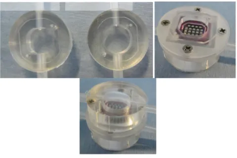
Place the bottom PDMS thin layer in the bottom holder.
Figure 3. PDMS layer and bottom holder
Use the black piece to center the chip: place it in the bottom holder, put the chip with tweezers, remove the piece while maintaining the chip at the bottom
Figure 4. step to place membrane on bottom holder
Bottom holder
Bottom PDMS layer
Piece to center the chip
XV Place the top PDMS thin layer on the system and close the system with the top holder
Figure 5. Top PDMS layer and holder system
Put a piece of biocompatible tape on each electrode side hole.
The system is now ready to be autoclaved and then put in a 6-well plate to do cell culture.
Place the holder on the bottom PDMS fluidic chamber (previously sterilized with ethanol and rinsed with water and then PBS) and close with the top PDMS fluidic chamber
Figure 6. How to build ILT2
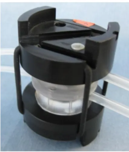
Close the system with the clamps (bottom and top are similar) and elastics. Bottom fluidic
chamber
Top fluidic chamber
XVI
Figure 7. ILT2 + clamps
Insert the spring contacts in the system (same for top and bottom). The voltage contact (to be connected to the inner electrodes of the chip) is on the side of the cables coming out from the contact holder.
Figure 8. ILT2 system + electrodes
Setting up the circuit:
Connect a tube of 300 mm in length, to each input of the bioreactor, using the male/female luer locks (Figure ).
XVII
Figure 9. Tubes of 300 mm in length connected to the input tubes of the bioreactor
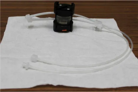
Connect a tube of 300 mm in length, to each output of the bioreactor (figure 10).
Figure 10. Tubes of 300 mm in length connected with the output tubes of the bioreactor
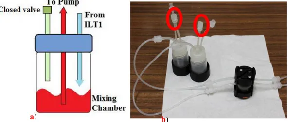
Connect each output tube to a mixing chamber using one of the 2 short tubes in the screw top. Insert a valve in the other short tube, in order to close it. Pay attention:
XVIII if the mixing chamber third way is not closed by this valve, there will be problems of liquid passage through membrane (figure 11).
Figure 11. a) A particular of the mixing chamber tubes is represented. b) The bioreactor joined with two mixing chambers.
Assemble the pump by inserting the 2 tubes (#2 and 3) in the pump head.
Note that the smaller tube (# 2 id 1mm) connects to the bottom circuit while the larger 2 mm id tube (#3) is for the top circuit
Connect the long tube of the mixing chamber to a tube of 300 mm in length and then to the inlet of pump.
Connect the bioreactor input tubes to the outlets of the bubble traps (in figure 12 bubble traps are ILT0 bioreactors in reverse position).
Connect the outlet of the pump to the bubble traps input tubes using 300 mm of tubing.
XIX
Figure 12. Complete system with the pump
Pump setting:
The flow rate in the top chamber should be twice that of the top part. Keeping in mind that above 300 μl/min the flow in top may present microturbulence, we suggest that the flows be fixed at 200 μl/min in the top half of the chamber and 100 μl/min in the bottom half. The rpm needs to be calibrated for each pump and circuit.
Filling ILT2:
While the top part of ILT2 is simple to fill because of the sloping roof, the bottom half is tricky because air bubbles may obstruct passage of nanoparticles and signaling molecules across the membrane. With the tubes connected as previously described, turn on the pump in order to fill the system
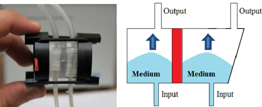
Make sure that liquid is flowing by looking at the tubes before and after the pump. Rotate the bioreactor in a vertical position, with the output of the ILT2 chamber at
XX the top. The medium will flow into the chamber as it is represented in figure 13. When the meniscus arrives near to the output tube, gently swing the bioreactor from left to right as shown in figure 14. This movement should allow the air bubble detachment from the PDMS base and the membrane. The flow will drive out the bubble and the medium will completely fill the bottom half of the bioreactor.
Figure 23. a) The position required to fill the bottom chamber, avoiding air bubbles. b) Schematic of the meniscus through the bioreactor.
Figure 14. Schematic of the motion required to detach the air bubbles from the bioreactor walls and the membrane.
XXI Method to connect ILT0 system to ILT2:
Place the ILT0 circuit between the ILT2 bottom output and the tube of 300 mm in length that is connected to mixing chamber (figure 15). Remember to maintain the ILT0 smaller tube in diameter as medium input.
It is convenient to fill ILT0 system before to fill ILT2, so connect it before to insert ILT2 in the circuit. By this way it is possible to start time table experiment when ILT2 is completely filled.
Figure 35. a) ILT2 circuit. b) ILT0 system and ILT2 circuit joined together.
Method to connect bubble traps system to ILT2:
Bubble traps allow to avoid any gas bubbles problem in ILT2 bioreactor. It is necessary to connect the bubble trap between ILT2 input and the tubes of 300 mm in length in connected to the pump outlets. Do it before to fill
XXII the bottom chamber of the ILT2. In case ILT0 in reverse position played as bubble traps, remember to maintain the bubble trap input (small tube in diameter) in a higher position than the output. By this way gas bubble enters in the trap and flow to the upper level. Here it will be entrapped because of the lower position of the outlet.
Figure 46. a) Bubble traps. b) Bubble Traps placed in properly way in order to be filled by liquid
When liquid fills bubble traps it is important to maintain the bubble traps system in vertical position because of the input and output tubes position. If this condition is not respected, liquid will flow out from the bubble trap without filling it sufficiently. Air bubbles could enter in the outlet and create problems in along the circuit. It is convenient to fill bubble traps system before to connect ILT2 in series.
XXIII
Figure 17. a) ILT0 system and ILT2 circuit joined together. b) Bubble Traps, ILT0 system and ILT2 circuit joined together.
XXIV t0 fill bubble traps
t1 fill ILT0 system
t2 Fill ILT2 system
t3 Start experiment
Table 1. on the left column time steps are represented. On the right column operation are reported.
Figure 58. ILT2 system with bubble traps and ILT0 in series
How to take samples
During experiments it could be useful take samples in order to evaluate concentration of NP at different times. Three way valves will be used to permit this operation. One valve
XXV will be positioned in the upper circuit, after ILT2. The other one will be placed in the bottom circuit, after ILT0. Maintaining the pump on, the operator will turn the valve, in order to open the communication between circuit and outside environment. Gilson will be used to take liquid samples, waiting that the liquid will flow out from the valve, according to pump pressure. Don’t try to take liquid samples before the right time, otherwise air could be flow inside Gilson tip. At the end, close the valve in the starting position, as it is represented in figure XX. Repeat the same operation with the other valve. It is important to make this operation as fast as possible in order to avoid a liquid lost and a pressure drop inside of the circuit.