I
Appendix A
The appendices describe bioreactor assembly and handling protocols which are distributed to InLiveTox partners. The protocols were tested and written by me, during the course of this thesis.
A.1 ILT1 protocol
Required material to set the ILT1 system (figure 1):
1) 1 Bioreactor ILT1
2) A tube for pump of 1 mm in inner diameter 3) A tube for pump of 2 mm in inner diameter 4) A pump
5) 6 tubing of 300 mm in length and 1 mm in diameter to connect the pump to the bioreactor, the bioreactor to each mixing chamber, the mixing chambers to the pump
6) 2 mixing chambers 7) 1 Holder
8) 1 membrane 9) 2 elastic rubbers
II Figure 1. Material: on the left it is possible to observe the material that is
required, on the right the pump is illustrated Circuit set up:
Place the bottom chamber on the bottom part of the holder (that one with the longest backings). The input tube is 1 mm in inner diameter and it has to be placed in the middle of the holder’s special offshoots.
Figure 2. It shows a particular of the bottom part of the holder. Pay attention to the long backings, as it is underline by the red circles
III Figure 3. Bottom chamber placed on the holder
Insert the membrane in the slit of the bottom chamber. Pay attention that the platinum isles on the chip are in correspondence with the holes for the electrodes realized in the PDMS part.
Figure 4. On the left side it is possible to see how to insert the membrane in the slit. Note the correspondence between platinum isles on the chip and the holes for the electrodes in the PDMS part. On the right side, the figure shows the membrane
placed in the correct position
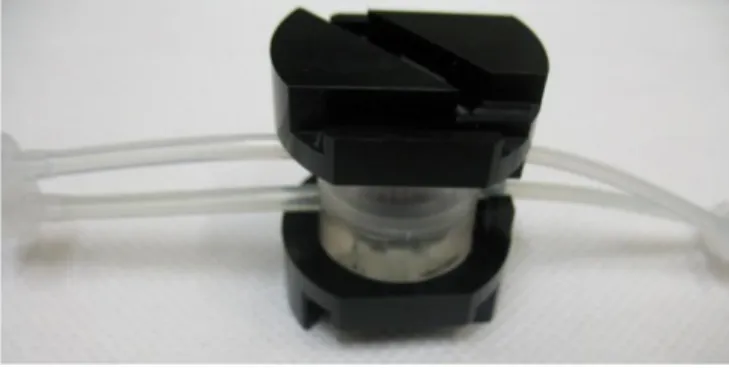
Close the bioreactor with the upper chamber. Also in this case pay attention to the correspondence between platinum isles on the chip and the holes in the PDMS part. Place the upper part of the holder. The input tube of the upper chamber has to be inserted between the holder’s offshoots. Fix the system using the elastic
IV rubbers. If a TEER measure is required, follow the indications that were provided by CSEM.
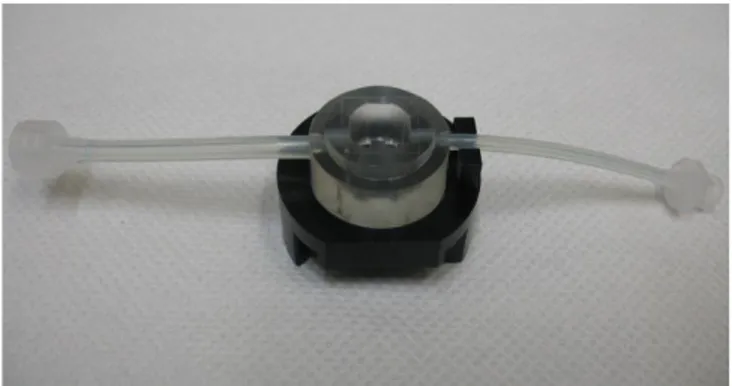
Figure 5. It shows the bioreactor placed on the holder
V Figure 7. A particular of the input tubing placed between the holder offshoots
VI
Join a tubing of 300 mm in length to each input of the bioreactor, using the male / female luer locks.
Figure 9. Tubing of 300 mm in length joined with the input tubes of the bioreactor
Join a tubing of 300 mm in length to each output of the bioreactor.
Figure 10. Tubing of 300 mm in length joined with the output tubes of the bioreactor
Join each output tubing to a mixing chamber. Use one of the 2 short tubes that passes through the top of the mixing chamber. Insert a filter to the other short way.
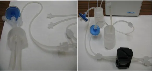
VII Figure 11. On the left a particular of the mixing chamber tubes is represented. On the
right the pictured shows the bioreactor which is joined with two mixing chambers
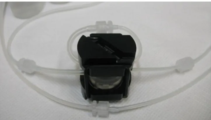
Join the long tube of the mixing chamber to a tubing of 300 mm in length and then to the pump. Do the same thing for the tubing that are joined to the bioreactor inputs
VIII Figure 13. Overview of the circuit joined with the pump (B)
Flow set up:
Set the pump to obtain a flow rate in the upper chamber circuit at 200 μl/min. Set the flow rate of the bottom chamber circuit at 100 μl/min. If the pump is calibrated using tube of 1 mm in diameter, and tubes of 1 mm in diameter are used to pump the medium in the bottom chamber circuit and tubes of 2 mm in diameter for the upper chamber circuit, set the pump at 100 μl/min. Remember: don’t use flow rate higher than 350 μl/min, to be sure to maintain a laminar flow condition.
Method to fill ILT1:
Join the tubes as previously described. Join the input and the output of the upper chamber together. The tubing that connect the pump to the input of the chamber and the output to the mixing chamber should be joined together.
IX Figure 14. The bioreactor is ready to be filled. The input tube of the upper chamber is joined with the output tube. The tubing that connect the pump to the
bioreactor and this one to the mixing chambers, are joined together
Turn on the pump. Make sure that the medium is in liquid stream, looking at the tubing before and after the pump. Rotate the closed bioreactor in a vertical position, maintaining the input of the bottom chamber in the lowest side. The medium will flow inside the bottom chamber, but it will not pass through the membrane pores. Pay attention to the meniscus that the medium creates (figure 15).
Figure 15 On the left note the position that is required to fill the bottom chamber, avoiding air bubbles. On the right the draw shows medium meniscus that flows
X
Avoid any air bubbles inside of the bottom chamber. They will cause a resistance to the solute passage through the membrane. When the medium meniscus arrives near to the output tubing, incline the bioreactor as shown in figure 16. This movement should allow the air bubble detachment from the PDMS wall and the membrane. The flow will drive out the bubble and the medium will fill completely the bottom side of the bioreactor.
Figure 16. It shows the movement that is required to detach the air bubble from the bioreactor wall and the chamber
Place the bioreactor on the work station. When the medium is arrived to the mixing chamber, stop the pump. Connect the input tube of the upper chamber to the tubing that comes from the pump. Connect the output tube of the upper chamber to the tubing that drive the flow to the mixing chamber. Start the pump. Pay attention that the medium fills the upper chamber completely. Check the drip in both the mixing chamber to be sure that the circuit hasn’t any closed tubing.
XI Method to connect ILT0 system to ILT1:
If it is required to connect any ILT0 bioreactor, do it before to fill the bottom chamber of the ILT1. Place the ILT0 circuit between the tubing of 300 mm in length that is connected to the ILT1 bottom output and the mixing chamber. Remember to maintain the ILT0 smaller tube in diameter as medium input. The tubing of 300 mm in length should allow all the movements required to fill the ILT1 bottom chamber, without any problems for the presence of the ILT0 circuit. Once all the system is joined, turn on the pump.
Figure 17. The ILT1 circuit is represented in the picture. Pay attention to the red arrow: it indicates where the ILT0 system has to be joined
Move the ILT1 bioreactor as described previously, to avoid any air bubble in the bottom chamber. The medium will fill the ILT1 and then will flow inside to the ILT0 circuit.