Simona Silvestri 50
Chapter 4
Kinetics of liquid phase in hybrid engine
4.1 Introduction
The aim of atomization is to increase the liquid surface area to enhance vaporization, mixing and burning. The fundamental mechanisms of atomization have been under wide experimental and theoretical study for more than a century. Reviews of liquid atomization mechanisms were provided by McCarthy and Molloy [20], Reitz and Bracco [21], Pilch et al. [22], and Hsiang and Faeth [23]. In spite of the importance of atomization, the mechanisms of breakup are still not well understood, even for the relatively simple case of a constant pressure injection from a single-hole nozzle into a stagnant gas [24]. The complexity of the breakup process is due to the unusually large number of parameters which influence it, including the details of the nozzle design, the liquid jet and the coflow air velocity and turbulence, and the physical and thermodynamic states of both liquid and gas. The process of atomization proceeds more easily if the liquid is present in a form that is more susceptible to disintegration. The most susceptible forms are thin jets or sheets of liquid, because they have the highest surface energy and thus the greatest instability.
Jet breakup phenomena have been divided into breakup regimes which reflect differences in the appearance of the jets as the operating conditions are changed. The regimes are due to the
Simona Silvestri 51 action of dominant forces on the jet, leading to its breakup, and it is important that these forces be identified to explain the breakup mechanism in each regime.
The phenomena that start the atomization process are the development of the waves on a liquid surface, the increase in their amplitude, and the loss of stability. Waves form on the surfaces of the jets and the sheets as well as on the surfaces of drops moving in the gaseous medium. The first solution to this problem was given by Rayleigh; he considered the vibrations and breakup of a cylindrical jet of non viscous liquid in a vacuum, including only the forces of surface tension. In his later work, Rayleigh took into consideration the viscosity of the liquid and demonstrated its influence on the disturbance growth rate.
Rayleigh’s theory was extended by C. Weber, who in addition considered the effect of aerodynamic forces acting on the liquid jet. A.S. Lyshevskii [25] and Yu F. Dityakin et al., L. A. Klyachko, V. I. Yagodkin and V.A. Borodin [26] investigated the effect of the velocity and density of the ambient gas and the viscosity of the liquid on the stability and breakup of a cylindric liquid jet. Bracco claims that the breakup and the development regions are the most relevant to the modelling of sprays. The existing experimental data are not sufficient to verify the developed spray models. Thus, accurate and detailed experimental measurements of the early stages of the liquid jet disintegration process are needed for different configurations.
Another different direction of theoretical research on liquid disintegration is based on the assumption that the disintegration proceeds in the vicinity of the outlet orifice and it is only turbulent pulsations that develop in the atomizer or on cavitation. Experiments that could confirm this theory are, however, difficult to conduct.
The theory studies only Newtonian fluids instead of non-Newtonian fluids that are necessary to experimental research.
Atomization is a process that occurs over multiple steps. Researches generally agree that there are at least two types; primary atomization, which is the initial disintegration of the jet into ligaments and large droplets, and secondary atomization, which is breakup of the ligaments and large droplets into small droplets.
A precise description of the rocket engine behaviour is currently unavailable. Most of the processes in rocket engines proceed simultaneously, the majority of which are not well understood. However a reliable description of the process in rocket engines can be made using realistic assumptions and simplifications.
Simona Silvestri 52 To describe the kinetics of the liquid phase in hybrid engines several assumptions were made. Let us consider the hybrid engines, which have a pre-combustion chamber, combustion chamber and a post-combustion chamber. The engines which have been examined, have liquid oxygen (or LOx) as oxidizer and hydroxyl terminated polybutadiene (or HTPB) as fuel. It was assumed that the atomization and the break-up of LOx jets occur only in the pre-chamber and afterwards the droplets enter into the combustion chamber, where they have the same velocity as the surrounding gas. The balance between the gas and the liquid phase of oxygen is determined by the evaporation rate of the liquid oxygen droplets. The gas temperature in the combustion chamber is much higher than the internal temperature of the droplets, which is equal to the boiling temperature of oxygen at a particular pressure. It was assumed that all considered processes proceed at constant pressure.
4.2 Stability and disintegration of liquid jets
The breakup of the liquid jet is a result of the complex interaction among inertial, viscous, and surface tension forces. Liquid viscosity has a damping effect on the growth of disturbances on the surface. Aerodynamic force, on the contrary, tends to promote them. Surface tension tends to pull the liquid together. Pressure oscillations and turbulence in the injected fluids and their surrounding gases also affect the dynamics of atomization [27].
In case of the liquid jet injection into a stagnant gas four main breakup regimes have been identified [24]. They correspond to different combinations of liquid inertia, surface tension and aerodynamic forces acting on the jet. The outcome of the jet breakup process is also influenced by the initial state of the jet as it emerges from the nozzle exit in each regime.
The unbroken length of the liquid jet, Lc, is a function of the jet exit velocity and it is a good
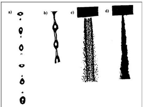
parameter to distinguish the four different regimes of breakup ( see fig.4.1). The first two breakup regimes are called the Rayleigh and first wind-induced breakup regimes in which the drops are pinched off from the end of the jet, with sizes comparable to that of the jet. In the Rayleigh regime the surface tension force, which induces axisymmetric oscillation of the jet surface, is mainly responsible for breakup; drops with diameters exceeding that of the jet are pinched off from the end of the jet. In the first wind-induced regime aerodynamic forces start playing a role
Simona Silvestri 53 and nonaxisymmetric sinuous oscillations appear; the drop diameter is of the order of the jet diameter. In both regimes the breakup occurs many nozzle diameters downstream of the nozzle.
Beyond the first wind-induced breakup regime there is confusion about the breakup length. This can be associated to separation and cavitation phenomena, which also exhibited hysteresis effects. Nozzle design effects are clearly very important for high speed jet break-up.
In the second wind-induced regime drop sizes are smaller than the jet diameter, produced by the unstable growth of short wavelength surface waves that are torn off from the jet surface; breakup starts with some distance downstream of nozzle. In the atomization regime the drop size is much smaller than the jet diameter and the breakup occurs very close to the nozzle exit.
Figure 4.1: Four jet breakup regimes. a) Rayleigh regime, b)first wind induced regime, c) second
wind-induced regime, d) atomization regime.
Miesse [28] studied the criteria of breakup regimes. He introduced the empirical relation
92 0
Re 100 L.
Z = − (4.1)
Where Z is the Ohnesorge number and ReL is the liquid jet Reynolds number which serves to
Simona Silvestri 54 Other criteria for the transition between regimes have been given by several authors.
Ranz [29] found that when the Weber number for the gas is 0.4, the inertia force of the surrounding gas reaches 10% of the surface tension force and this value marks the beginning of the first wind-induced breakup regime in which the effects of the ambient gas are no longer negligible.
It was found that Rayleigh breakup occurs for
WeL > 8 and Weg < 0,4 or for Weg < 1,2+3,41*Z0,9 (4.2)
as the alternative criterion, the maximum in the jet breakup length occurs at Weg=1,2+3,41*Z0,9 from numerical results of Sterlingg and Sleicher [30].
Ranz [28] argued that the gas-inertia force is of the same order as the surface tension force when Weg=13. This serves as the definition of the end of the first wind-induced regime, which occurs
when
1,2+3,41*Z0,9 < Weg <13 (4.3)
Weg >13 marks the onset of the second wind-induced regime, where the interaction with the
surrounding gas starts to become dominant. The criterion for the second wind-induced regime given by Miesse [27] as
13< Weg <40,3 (4.4)
In the second wind-induced regime, breakup occurs at some distance downstream of the nozzle exit and results in droplets with sizes much smaller than the jet diameter. The mechanism of breakup here is thought to be due to the unstable growth of surface waves on the jet.
The four regimes are shown in the fig. 4.2. The regimes can be found on a plot of Weber number vs Reynolds number (or on a plot of Weber number vs Ohnesorge number) and they are separated on a log-log plot by three straight lines of negative slope [27].
Simona Silvestri 55
Figure 4.2: Modes of disintegration on a liquid Reynolds number and Weber number plane.
Farago and Chigier studied how to visualize the rupture of round liquid jets under conditions with or without coflowing gas stream. In the far field they observed three different types of regimes:
- Rayleigh breakup, in which the liquid jet is disintegrated into droplets without the formation of ligaments and the mean drop diameter is of the order of the jet diameter. The maximum is twice the jet diameter. This type of breakup can be axisymmetric (We<15) and nonaxisymmetric (15<We<25).
- Jet disintegration via membrane-type ligaments (25<We<70), in which the round jet develops into a thin sheet (membrane) before breaking into drops. Liquid accumulating at the edges of the thin sheet forms a liquid frame. The diameter of the frame is smaller than the diameter of the emerging intact liquid jet. The thick frame breaks into drops via the nonaxisymmetric Rayleigh mechanism.
- Fiber-type breakup (100<We<500), in which there is the formation of fibers and their peeling off the main liquid core. The fibers break into droplets by the nonaxisymmetric Rayleigh-type jet disintegration mode. The diameter of the newly formed fibers
Simona Silvestri 56 increases with increasing axial distance from the nozzle exit and the size of the drops generated further downstream is larger than those formed closer to the nozzle exit.
Every category can be divided into two submodes: pulsating jet disruption as capillary, helical, and Kevin-Helmholtz instability and super pulsating jet disruption that is connected to an extremely high periodic change between low and high density regions in the spray.
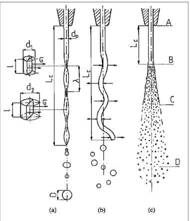
The character of the liquid jet disintegration depends on the velocity of the discharge from the nozzle [31]. Three different forms of the disintegration are caused by axisymmetric waves, asymmetric waves and aerodynamic forces. It is important to note that the outcome of the jet breakup process is also influenced by the initial state of the jet as it emerges from the nozzle exit in each regime.
In the disintegration of a liquid jet caused by axisymmetric waves incidental internal perturbations cause narrow bands to develop in the jet (see Fig.4.3).
Figure 4.3: Disintegration of a cylindrical jet of liquid caused by (a) axisymmetric waves; (b)
Simona Silvestri 57 From the equilibrium condition between the pressure forces and the surface tension forces it is possible to verify that the pressure in narrow bands, p1, is higher than the pressure in wider
bands, p2: lσ lp d1 1 =2 (4.5) lσ lp d2 2 =2 (4.6) Hence: 2 1 2 1 p d d p = (4.7)
Since d1 < d2, it is found p1 > p2. Thus the liquid is forced from the narrow bands to the wider
bands, leading to the development of the drops. This type of disintegration is only due to the surface tension. The surface energy is a product of the surface tension and the surface area. The lower the surface energy, the more the system is stable.
The problem of a jet in vacuum with initial diameter d0, length λ and diameter of the drop D was studied theoretically by Rayleigh, who obtained
0
436 1, d
D≥ (4.8)
It follows that the jet is unstable for disturbances whose wavelength is greater than the perimeter of the jet.
C. Weber extended this relation and obtained for a viscous liquid
6 1 5 0 0 Re 3 1 436 1 + = , L We , d D (4.9)
where WeL is the Weber number
σ d ρV We L L 0 2 = (4.10)
is the ratio of the inertia force of the surrounding gas and the surface normal force (due to the surface tension). It is an important parameter for the jet breakup.
Simona Silvestri 58 L L L µ d V ρ 0 Re= (4.11) where
VL, ρLand µLdenote the velocity, density and the viscosity of the liquid, respectively.
Another important parameter is the Ohnesorge number:
Re 0 L L L We σd ρ µ Z= = (4.12)
It is a dimensionless number that relates the viscous forces to inertial and surface tension forces.
In reality the drops have various diameters because they develop from segments of the jet with different constrictions. The influence of the liquid viscosity is manifested by vibration dumping, which causes delay or lack of jet disintegration.
When the discharge velocity increases, the jet is acted upon by aerodynamic forces that cause distortion of this axis. These distortions increase constantly because of pressure forces caused by the environment. Negative pressure develops in the convexities and overpressure develops in the concavities under the influence of asymmetric waves, and the jet disintegrates into smaller drops than are produced by axisymmetric waves. During the intensive action of the aerodynamic forces the jet disintegrates into relatively small drops and it is possible to distinguish three different zones (see Fig.4.3 c):
• AB is the compact jet zone in which vibrations develop
• BC is the disintegration zone in which the disintegration proceeds because the waves have a small length compared to the jet diameter
• CD is the drop zone in which the liquid disintegrates almost immediately into small jets and consequently into drops before waves can develop because of the very high velocity
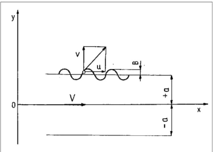
A jet of a viscous liquid with a wavy surface and infinite length is moving in a stationary, incompressible, and viscous gas (see Fig.4.4). The Navier-Stokes equations, neglecting the mass forces and the flow continuity equation, have the following form:
Simona Silvestri 59 ∂ ∂ + ∂ ∂ + ∂ ∂ − = ∂ ∂ + ∂ ∂ + ∂ ∂ ∂ ∂ + ∂ ∂ + ∂ ∂ − = ∂ ∂ + ∂ ∂ + ∂ ∂ = ∂ ∂ + ∂ ∂ 2 2 2 2 2 2 2 2 1 1 0 y v x v ν y P ρ y v v x v u t v y u x u ν x P ρ y u v x u u t u y v x u j j j j j j (4.13) where
u, v are the liquid velocity components on the jet boundary;
j is the index of the fluid type ( j=1 for the jet liquid, j=2 for the gas environment)
Figure 4.4: Scheme of the surface profile of a liquid jet
For the liquid ( j=1) in equation (4.13) the velocity components and the pressure have to be substituted with the following values:
u = U+u1, v = v1, P = P0+P1
where
v is the velocity of the liquid,
u1, v1, P1 are parameters of the disturbances,
P0 is the pressure of the liquid before superposition with the disturbances.
Simona Silvestri 60 ∂ ∂ + ∂ ∂ + ∂ ∂ − = ∂ ∂ + ∂ ∂ ∂ ∂ + ∂ ∂ + ∂ ∂ − = ∂ ∂ + ∂ ∂ = ∂ ∂ + ∂ ∂ 2 1 2 2 1 2 1 1 1 1 1 2 1 2 2 1 2 1 1 1 1 1 1 1 1 1 0 y v x v ν y P ρ y v V t v y u x u ν x P ρ x u V t u y v x u (4.14)
The parameters of the disturbed motion are periodic functions of the x coordinate and time t. The solution has the following form:
[
]
[
]
{
}
[
]
[
]
{
}
[
A (ky) A (ky)]
i(ω kV) i(kx ωt) const ρ P ωt) i(kx y) (γ B y) (γ B ik (ky) A (ky) A k v ωt) i(kx y) (γ B y) (γ B γ (ky) A (ky) A ik u + − − + = − + − + = − + + + = exp sinh cosh exp cosh sinh cosh sinh exp sinh cosh sinh cosh 2 1 1 1 1 2 1 1 2 1 1 1 2 1 1 1 2 1 1 (4.15) wherek=2π/λ is the wave number,
λ is the wavelength of the disturbance, ω is the frequency of vibrations, A1, A2, B1, B2 are constants, 1 2 2 1 v kV) i(ω k γ = − − .
For the ambient environment (j=2) the equation (4.13) has a similar form and describes the development of disturbances in this medium with the constant C1, C2, D1, D2.
The pressure in the fluid, Pσ, caused by the surface tension σ for the two dimensional case and for small disturbances is given by:
[
i(kx ωt)]
B σk Pσ = exp − 2 (4.16) whereB is the amplitude (see Fig. 4.3)
To find the solution for the simplified equation (4.10) it is necessary to write the boundary conditions:
Simona Silvestri 61 1. in infinity the disturbance decays.
2. the velocity of the motion of the jet surface (boundary) must be equal to the transverse velocity component for y = ±a
3. for y = ±a the requirement of lack of slip between the liquid and ambient medium must be satisfied
4. for y = ±a the continuity of shear stresses must be preserved
5. the pressure difference for the liquid and ambient medium at y = ±a is balanced by the pressure Pσ
The final equation that represents the base for the analysis of jet disintegration can be written as:
[
]
− − = = − + − + − + − − − a) (γ A B i (ka) σk kV) i(ω ke γ A D i e k A C µ a) (γ kγ A B i (ka) k µ (ka) kωω i(ω ρ a γ ka 1 2 2 3 2 2 2 2 2 2 2 1 1 2 2 2 1 2 1 cosh cosh sinh sinh 2 sinh 2 (4.17)Regarding the atomization of fuels in engines it is possible to neglect the viscosity of the liquid and the equation 4.13 becomes:
0 tanh 2 tanh tanh tanh 2 tanh 1 3 1 2 2 1 3 1 2 1 1 2 1 2 = + − + + + + − + (ka) iV ρ k µ (ka) V k ρ σk iω (ka) iV ρ k µ (ka) ρ k µ k (iωi ρ ρ (ka) (4.18) In dimensionless form: 0 2 1 2 1) + (K +iL)iω +R+iS= H(iω (4.19) where
( )
ε M H =1+ ⋅coth We ε L 2 1 =Simona Silvestri 62
( )
( )
σ a ρ iω ω i ka ε Lp We ε S We ε ctnh ε ε R ε N ( ε Lp K 3 1 1 3 2 2 2 2 1 coth 1 2 = = = = − ⋅ = + =The dimensional parameters that characterize the process of atomization are:
Weber number (We)
σ a V ρ We 2 2 1 = Laplace number (Lp) a σ ρ µ Lp 2 1 1 2 1 =
Ratio of gas and liquid densities (M)
1 2
ρ ρ M =
Ratio of gas and liquid viscosities (N)
1 2
µ µ N=
The equation (4.19) is a quadratic equation with respect to the vibration frequency iω.
The imaginary part of the solution determines the character of the motion’s stability. The positive sign of the real part represents the vibrational decay; instead the negative sign represents the increase in amplitude that leads to loss of stability and disintegration into drops.
In case of atomization of a liquid in a gaseous medium the density and the viscosity ratio of gas and liquid are very small. For small wavelengths the dimensionless wave number is ε >3. In this case the solution becomes [31]:
+ − − = 2 2 2 2 2 2 1 MWe ε Lp ε ε Lp ε ω (4.20)
Simona Silvestri 63 It is possible to evaluate ω1 as a function of the dimensionless wave number, ε, for different values of 1/Lp and constant values of We, M, N.
From different diagrams it is possible to extrapolate the dimensionless equation of:
308 0 21 1 max 1 0536 . . Lp (MWe) . ω =− (4.21) 22 0 8 0 173 0 . . opt . (MWe) Lp ε = (4.22)
These are used to calculate the length of the compact jet and the average diameter of the drop:
0733 0 266 0 0 . . __ Lp K(WeM) d D = − − (4.23)
this equation is applied to disturbances with very short wavelengths.
The liquid intact length is one of the most important parameters in characterizing the breakup region. The length of the compact jet, Lc, depends mostly on jet velocity, geometry of the outlet
orifice, character of the jet, physical properties of the fluid, and the ambient medium and is defined as the length of the jet that is hydraulically connected to the nozzle exit plane. For the jet in which the disintegration is caused by axisymmetric waves, Lc is derived from the Weber
equation: We δ R d Lc ln 0 = (4.24)
The parameter R/δ is determined experimentally. For a laminar jet ln(R/δ)≈24; for a turbulent jet ln(R/δ)≈4.
The general shape of the intact length versus jet velocity curve is shown in fig. 4.5; this curve is also called jet stability curve, and its shape is agreed upon by many researches. In the range of small velocities the length Lc of the compact jet increases linearly. The linear relationship is
marked with the line AB. As the velocity increases further, Lc increases slightly up to the line CD
and then decreases significantly. The line CD corresponds to the transition from disintegration caused by axisymmetric waves to disintegration caused by axisymmetric waves.
Simona Silvestri 64 A dimensionless equation derived from the equation (4.21) is [32]:
21 1 308 0 71 0 0 . . . c M Lp CWe d L = − − − (4.25) where: d0=2a,
C=442 is a constant for continuous jet atomizers, C=372 is a constant for intermittent jet atomizers.
Figure 4.5: Length dependence of a compact jet on the discharge velocity V.
4.3 Stability and disintegration of liquid sheets
The dynamics of sheets of fluid was studied by Savart, Dorman, Fraser, Eisenklam and Dombrowski; they were the first to describe the breakup and drop formation of plane fan sheet. Three different modes of disintegration have been identified [27]. In the rim mode, the surface tension creates forces that cause the free edge of a liquid sheet to contract into a thick rim; the rim
Simona Silvestri 65 then breaks up by the same disintegration mechanism of a free jet. This mode is prominent where the viscosity and the surface tension of the liquid are both high. In the perforated-sheet disintegration mode, holes appear in the sheet and are delineated by rims formed from the liquid that was initially included inside. These holes grow rapidly in size until the rims of adjacent holes coalesce to produce ligaments of irregular shape that finally break up into drops of varying size. In the wave disintegration there is the formation of wave motion on the sheet and the absence of perforation; the areas of the sheet correspond to half or full wavelengths of the oscillation and they are torn away before the leading edge is reached. Moreover, temporal and spatial stability analyses [33] show that liquid viscosity plays a dual role in the stability of liquid sheets. At low Weber numbers, viscosity introduces an additional mode of instability, which can grow faster than the aerodynamic instability. However, at high Weber numbers, linear theory shows that aerodynamic instability always dominates and liquid viscosity always reduces the disturbance growth rates and shifts the dominant disturbances to longer wavelengths.
The disintegration of the sheet [31] is also correlated with the liquid discharge velocity from a rotary atomizer and it is possible to distinguish three different types:
• Discharge with a velocity of several meters per second: the thickness of the sheet decreases as the distance from the atomizer increases. The perforations grow and create a net of narrow jets, which after loss of stability disintegrate into drops (see fig.4.6 a). • Higher discharge velocities: there are annuli and circumferential waves. At the beginning
there is the formation of annulus waves in the orthogonal direction to the velocity of the fluid. They cause the disintegration of the sheet into annuli which are then disintegrated into drops (see fig. 4.6 b).
• High discharge velocity (about 100 m/s): the ambient medium causes such strong disturbances that the sheet disintegrates into drops before the waves develop (see Fig. 4.6 c).
Simona Silvestri 66
Figure 4.6: Drop development in a swirl atomizer: (a) sheet disintegration due to perforation; (b) sheet
disintegration due to wave phenomena; (c) liquid atomization.
The model in the following figure has been used to study the disintegration of the liquid sheet:
Figure 4.7: Scheme of the disturbed surface of a liquid sheet.
The following assumptions were made:
1. Both fluids (the liquid and ambient gas) are non viscous and incompressible. 2. The amplitudes of initial disturbances are small compared to the wavelengths.
Simona Silvestri 67 3. The liquid is stationary with respect to the coordinate system
4. Gas flows with constant velocity of the liquid and the gas. 5. The sheet has infinite length.
6. The sheet thickness is limited by the coordinates y= +a and y= -a.
During the relative motion along the sheet, a gas causes the pressure distribution and this increases the amplitude of the disturbance. From the balance between the liquid pressure (p1), the
ambient pressure (p2) and the pressure (pσ) due to the surface tension, it was found:
2 2 2 1 x b σ p p p σ ∂ ∂ − = = − (4.26) Where
b is the displacement of the liquid surface from the equilibrium position.
The equation of the disturbed surface is:
kx) (nt B a y= + cos + (4.27) where
n is the time coefficient, k is the wave number,
B is the amplitude, which for loss of stability becomes infinity for time t.
The initial flow is assumed to be steady, but any perturbation induces unsteady flow in each phase that it is assumed to be irrotational, and thus associated to a perturbation potential:
0 2 1 2 2 1 2 = ∂ ∂ + ∂ ∂ y Φ x Φ (4.28) and the boundary conditions become:
for y≅+a x b V t b dt dy y Φ ∂ ∂ + ∂ ∂ = = ∂ ∂ 1 (4.29)
Simona Silvestri 68 for y≅−a 0 1 = ∂ ∂ y Φ (4.30) (because according to the assumptions the normal velocity component for the liquid, dy/dt, only exists for the upper surface.)
The solution for the continuity equation is:
[
C (ky) D (ky)] [
E (nt kx) F (nt kx)]
Φ1 = cosh + sinh ⋅ cos + + sin + (4.31)
The constants C, D, E, F can be derived from the equation (4.27) to the equation (4.31); thus the solution becomes:
[
B (nt kx) Bn (nt kx)]
(ka) (ky) (ka) (ky) k Φ ⋅ + − + + = cos sin cosh sinh sinh cosh 2 1 1 & (4.32) where dB/dt B&= .Similar equations are used to describe the motion of the ambient gas.
On the plain of fluids separation the pressures of the fluids are derived from Lamb’s equation:
∂ ∂ + ∂ ∂ + ∂ ∂ − = 2 2 2 1 y Φ x Φ t Φ ρ C pj j j j j j (4.33) in which
j=1 refers to the liquid and j=2 to the gas.
Differentiation of eq. (4.32), substituting in the eq. (4.33), and neglecting the squares of terms B, it was obtained for the liquid and the gas respectively:
(
)
+ + + − − + = (nt kx) k B nα kx) (nt B n B k α ρ C p cos sin 2 2 1 1 1 & & & (4.34)Simona Silvestri 69
[
]
+ + + + − + − − = (n kV) (nt kx) k B kx) (ht B kV) B(n k ρ V ρ C p 1 cos 2 sin 2 1 2 2 2 2 2 2 & & & (4.35) where ctgh(ka) tgh(ka) α= + 2 2 B/dt d B&&= .To find the constants C1 and C2 the case of a flat surface was considered, thus for example in
absence of disturbances, the ambient pressure is equal to the liquid pressure (p1=p2) and a
correlation between the two constants was found.
Differentiation of eq. (4.27) and substituting eq. (4.34) to eq. (4.26), yields
[
]
0 sin 2 cos 2 2 1 2 2 2 2 1 = + + + + + + − − + + − kx) (nt kV) (n k B ρ B n k α ρ kx) (nt B σk B kV) B(n k ρ ) B B (n k α ρ & & & & & & (4.36)This equation is called the dispersion equation and it is satisfied when the terms in front of sinus and cosines are zero; hence
= + + = + − + + + + = 0 2 2 2 2 2 2 2 4 1 3 2 2 2 M α MkV n B M) (α ρ σk M α V Mk n M α MkV n B B & & & (4.37) where M=ρ2/ρ1.
To determine the stability the system has to be solved. Two solutions are obtained. In case the amplitudes are functions of time
(
B&≠0)
it was found:M α MkV n 2 2 + = (4.38)
Simona Silvestri 70 M) (α ρ σk M) (α V αMk B B 2 2 2 2 1 3 2 2 2 + − + = & & (4.39)
The left-hand side of the eq. (5.39) expresses the relative acceleration of wave amplitude; the right-hand side represents the aerodynamic and surface tension forces. The most important case for the stability is the case of positive acceleration of the amplitude (B&& /B>0). This condition can be expressed as B&& /B=β2
Thus the solution of this equation has an exponential form
βt βt e L e K B= ⋅ + ⋅ − (4.40)
with the constants K and L constants. In a dimensionless form the equation becomes:
2 1 1 2 2 2 4 2 2 2 + − + = M) (α ρ amV πσ M) (α αM m π V βa (4.41) where m=λ/a, V βa
S= is the speed of the amplitude growth,
σ a V ρ We 2 1
1 = is the Weber number for the liquid.
This equation shows that the disintegration of thick sheets is possible with short waves only if there is a sufficient increase of the Weber number of the liquid and then an increase of the velocity of the liquid, but to do this high energy is necessary.
With this analysis the approximate dimension of the drops can be calculated.
First the sheet is disintegrated into annuli and then the annuli are disintegrated into drops. It was assumed [31] that the annulus of a sheet with thickness 2a and width λ* is transformed by surface tension into an annulus with a circular cross section. It is possible to evaluate the diameter of the cross section calculating the surface of the annulus (see fig. 4.6 b):
* 2 1 2 4 aλ πd ≈
Simona Silvestri 71 The disintegration proceeds in accordance with Rayleigh’s theory, for wavelengthλ1 ≈4 d.5 1. The
maximum drop diameter possible for the drop can be determined by requiring the volume of the drop, assumed spherical, equals the volume of the annulus (a cylinder with diameter d1 and length
λ1): 1 2 1 3 4 6 λ πd πD =
Thus the drop diameter is:
*
aλ .
D=212 2 (4.42)
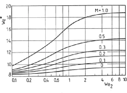
The wavelength λ* corresponds to the maximum velocity of amplitude growth present in the Weber number σ λ V ρ We * * 2 2 = (4.43)
and in other form
σ a V ρ We 2 2 2 = (4.44)
When the wavelength is equal to λ* a maximum velocity of amplitude growth for a given Weber number We2 it is possible to find the relationship between We1 and We*, as showed in fig.
Simona Silvestri 72
Figure 4.8: Effect of the sheet thickness included in Weber number We2 on the wavelength λ *
included in We*.
Many mathematical approaches to study the sheet breakup are presented in literature. Hagerty and Shea [34] and Squire [35] first considered temporal behaviour on an infinite liquid sheet at low gas to liquid density ratio. Sirignano and Mehring [36] extended the analysis to high density ratio.
4.4 Secondary disintegration of drops
As mentioned in the previous paragraphs the disintegration of a liquid jet can be studied at near field of the nozzle and at far field [27].
In the near field the difference of velocities of gas and liquid leads to a surface instability and a stripping of filaments or drops from the jet surface. At far field the gas velocity decreases because of the mixing with the external atmosphere, and the instability scales grow. At the same time the secondary atomization process takes place. The largest droplets and the ligaments produced by the primary atomization are broken up into small droplets. The breakup time of these droplets can be expressed as a function of the local relative velocity and the ratio of the gas to liquid density. The breakup time together with the initial droplet velocity is very important in the combustion
Simona Silvestri 73 application because it gives the distance from the injector where the secondary atomization takes place to the flame position.
The secondary atomization occurs because of aerodynamic forces when the drops enter an area where the dynamic pressure of the gas is increased [30]. The pressure distribution of the gas around the droplet develops on its surface and leads to the deformation of the drop. If the aerodynamic force is higher than the surface tension, the drop is deformed and later disintegrated. At the equilibrium condition for the forces it is possible to find the drag coefficient (CD) and the
critical Weber number (We*):
πDσ V ρ πD C G D = ⋅ = 2 4 2 2 D G * C σ D V ρ We 8 2 ⋅ =
The critical Weber number represents the criterion for deformations that lead to the secondary disintegration of a drop. From the last equation it is possible to determine the maximum drop diameter (Dmax) that can exist under given conditions, since all drops bigger than Dmax should
disintegrate: 2 max V ρ σWe D G * =
Secondary atomization proceeds when the Weber number is larger then critical. The higher the Weber number, the smaller the size of the secondary drops. It was established that the secondary atomization occurs in a range between two critical Weber numbers (We1* and We2*),
for We=We1* 10 to 20% drops disintegrate, and for We=We2* the remaining drops disintegrate
under the given conditions. However, there is a discrepancy in the different results due to the various factors that influence the secondary atomization. Nevertheless it was established that in the range of Weber numbers We*=6 to 50 three types of disintegration can exist. The differences between them stem from the complex interaction between the gas flow and the drop:
-a non uniform pressure distribution develops on the drop surface and it is the main cause of drop deformation
Simona Silvestri 74 -because of the gas flow, a boundary layer grows on the surface of the drop
-acceleration of the drop due to the acting of gas on its front surface, this causes Taylor instability on the surface.
In general there are two kinds of drop disintegration that are divided into several types. All types start from flattening of the drop.
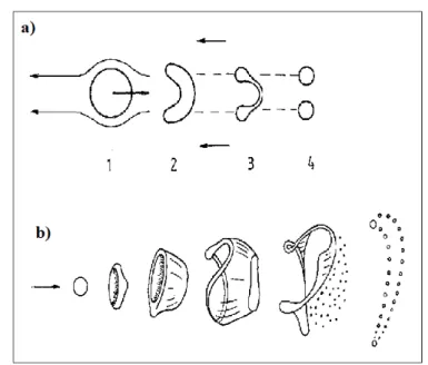
The first kind includes:
1. Single drop division (fig. 4.9a). The drop disintegrates into almost identical drops.
2. Parachute-type disintegration (fig. 4.9b). The drop flattens and is blown out in the direction of the flowing gas in shape of a parachute.
3. Chaotic disintegration. Several parachutes develop on one drop and produce small drops and liquid threads of various shapes during the disintegration.
The second kind includes:
1. Shear mechanism. The surface layer of the liquid is torn off from the rim of the oblate drop and rapidly transforms into a cloud of small drops.
2. Burst disintegration. The drop disintegration proceeds so rapidly in the whole volume that the shearing is almost unnoticeable.
The overall process of atomization can be characterized by several dimensionless parameters. An important parameter in the assessment of the disintegration type is the WeRe-0.5. It is possible to divide three different regions of breakup in function of the Weber and Reynolds numbers. The graphic in fig. 4.10 shows area I, II, III referring to various types of drop disintegration and region A encircled by line B-B. In area I and II play a dominant role the Taylor disturbances that lead to the parachute and claviform types. The lower part of curve B-B correspond to condition WeRe-0.5>0.3, where periodic disturbances appear on the drop surface. As the term WeRe-0.5 increases, the shearing off of the surface layer occurs on the larger surface, which leads to burst disintegration, region III. However, the graphic is limited at small ranges of We and WeRe-0.5
Simona Silvestri 75 because of the significant discrepancy between the data obtained from different authors due to the many factors, which can influence the secondary atomization. Some of these factors can be the type of the load acting on the drop, the liquid viscosity, the time of disintegration and the drop diameter.
For increasing relative velocity, there are two different types of deformation: for liquids with high viscosity the drop disintegration proceeds like a parachute type, the sheet of the parachute disintegrates into large numbers of small drops, and the rim disintegrates into a small number of large drops. For a liquid with low viscosity the oblate drop is blown out in the form of a hat, which is directed with its convex side towards the oncoming gas. This type of disintegration is caused by the Rayleigh-Lamb-Taylor instability. The influence of viscosity on the critical Weber number is shown in fig. 4.11; for both increasing and decreasing relative velocities of the gas and the drop. The influence of the duration of contact between a drop and gas on We*is characterized by the fact that for increasing contact time, We* decreases. The time of drop disintegration can be calculated from empirical equations, and it was established that the best agreement with experimental data was obtained with the Engle equation:
G L ρ ρ V D . t=28
Where t is the time of disintegration (ms), D is the drop diameter (mm) and V is the relative velocity of the drop and gas (m/s). The drop disintegration is influenced by the duration of the different processes as drop deformation, drop acceleration, boundary layer formation on the drop and increase of the amplitude of disturbance on the drop surface; if these processes have different durations, the time of disintegration is controlled by the shortest one.
The effect of drop diameter on We* has not been well studied, but the experiments on this field show that small drops, particularly of viscous liquids, are more resistant to the secondary atomization, which corresponds to higher We* values (fig. 4.12).
Simona Silvestri 76
Figure 4.9: a) Simple drop division; 1-4, consecutive stages of disintegration; b) Parachute-type drop
disintegration.
Simona Silvestri 77
Figure 4.11: Influence of viscosity on the critical Weber number We*: 1) increasing relative velocity; 2) decreasing relative velocity.
Figure 4.12: Dependence of the critical Weber number We*on the drop diameter D; 1) µL=1x10⁻³ Pa·s;
2) µL=4.8x10
-3
Pa·s; 3) µL=97x10 -3
Simona Silvestri 78
4.5 Single droplet combustion
The theory allows for understanding of the physical and chemical processes occurring in a burning droplet and is in good agreement with the experiment. It was developed by Spalding (1953) [38], Godsave (1953)[39] and Goldsmith and Penner (1954). In this study Williams arguments [40] are used. Furthermore it is supposed that the behaviour of all droplets had the same characteristics. The overall scheme of the process is shown in fig. 4.13.
The model considers a spherically symmetric droplet of LOx in a fuel environment. The following assumptions are used:
a) The system has spherical symmetry.
b) Combustion of droplet is quasi-steady (i.e. the fuel is consumed in the reaction zone at the same rate that it evaporates from the drop).
c) The drop temperature is fixed and is equal to the boiling temperature of LOx . d) Radiation, Soret and Dufor’s effects are neglected.
Figure 4.13: Burning combustion model of an oxygen droplet in a fuel atmosphere.
Liquid droplet
Oxidizer
Oxidizer
Reaction zone Fuel
Fuel Combustion products rl
Simona Silvestri 79 The mass flow of oxygen
( )
m& leaving the droplet can be determined from continuity equations: dt dr ρ πr ρ πr dt d m l l l l l 2 3 4 3 4 − = − = & (4.45) or( )
2 2 1 4 l l l l l d dt d dt dr r r πρ m − = − = & , (4.46) or( )
K r πρ m dt d d l l l =− 2& =− 2 , (4.47) Kt d dl = 2 − 0 2 . (4.48) whereρl is the liquid density and is assumed as a constant, dl (=2rl) is the diameter of the liquid droplet ,
K is the evaporation constant.
The equation (4.48) is supported by experimental observation that the mass flow m& is proportional to the drop radius rl. The equation results in linear variation of d2 with t.
Spalding elaborated the theory [38], which gives the expression for K. The combustion for a single droplet is assumed to be limited by evaporation of oxygen from the droplet. Additional assumptions are used to get the expression for K.
Conservation of energy at the droplet surface gives
+ − =
∑
∑
= = L h C h C πr m dr dT λ il n i n i l i i i 1 1 2 4 & (4.49) whereL is the heat of vaporization per unit mass of oxygen at temperature Tl. Heat transfer
coefficient λ, heat capacity Cp and the product ρDare set to constants and independent on
Simona Silvestri 80 The boundary conditions, expressing the assumptions that there is no reaction in the liquid phase or at infinity, are
T = Tl, Yox = Yox, l, for r = rl;
T = Tff, Yfu = Yfu, ∞, for r = r∞;
where:
Tl is the boiling temperature of liquid oxygen,
Tff is the temperature at far field.
In order to obtain the analytical solution, it is necessary to make an additional assumption, namely that the chemical reaction is given by
fuel + oxygen → products (CO2, H2O, etc.)
and that it is instantaneous (infinite reaction rate), or in other words that reaction zone is thin. As a consequence, the flame is confined to a surface into which oxidizer and fuel enter in stoichiometric ratio, thus disappearing.
The solution obtained for constant (or average) heat capacity and heat conductivity is
(
B)
D πr
m& =4 l ln1+ (4.50)
where
D is the diffusion coefficient of gaseous oxygen in the decomposition products of HTPB. For engineering evaluation the decomposition products of HTPB can be assumed as methane (4.51):
− = − T S T D D a CH O exp 273 0 4 2 (4.51)
Simona Silvestri 81
D0 0.22 cm2/s
a 1.695
S 44.2 K
Table 4.1: Table of physical values for diffusion coefficient. [43]
The transfer number B, also called the Spalding number, is given by
(
)
+ − = υ Q T T C L B 1 p f l (4.52)Where Q/υ is the specific heat of combustion divided by the stoichiometric coefficient.
It qualitatively represents the ratio of an impetus for interphase transfer to resistance opposing that transfer. From the viewpoint of energetic, the sum of the heat released per unit mass of fuel consumed and the difference in the thermal enthalpy per unit mass between the ambient gas and the gas at the surface of the droplet comprise the impetus for transfer, while the heat of vaporization L per unit mass of oxidizer vaporized is the resistance.
To calculate the transfer number and the mass flow it is necessary to know the adiabatic flame temperature and the boiling temperature of LOx.
5.5.1 Adiabatic flame temperature
The adiabatic flame temperature is the temperature that results from the complete combustion process that occurs without heat transfer or changes in kinetic or potential energy.
For ideal gas it is possible to write the correlation between the variation of the combustion chamber heat and the enthalpy:
∆Q i ) T( T dT pi c fi h i N f T T dT pi c fi h i N = ∑ ∫ + − ∫ + 0 o o o o , (4.53)
Simona Silvestri 82 ')λ ν " (ν N N i i ) ( i i = + − 0 . (4.54) where:
Ni is the number of the moles of theith species,
Ni(0) is the initial number of the moles of the ith species,
νi” is the stoichiometric coefficient of the products,
νi’ is the stoichiometric coefficient of the reactants, o
fi
h is the enthalpy of formation of the i-th species,
cpi is the specific heat at constant pressure,
Tf is the flame temperature,
T(0) is the initial temperature,
o
T is the temperature at standard condition, ∆transferred to the system.
At adiabatic conditions the transferred heat equals to zero, thus
0 0 = ∑ ∫ + − ∫ + i ) T( T dT pi c fi h i N f T T dT pi c fi h i N o o o o (4.55)
The reaction between the droplet of LOx and the solid fuel of HTPB is in stoichiometric ratio and given by: 2 2 2 6 4H 5,5O 3H O 4CO C + → +
Simona Silvestri 83 Thus in this case the equation (5.53) becomes:
0 0 0 2 2 2 6 4 6 4 6 4 6 4 2 2 2 6 4 6 4 6 4 6 4 2 2 2 2 2 2 = + − + − + + + + + + + + +
∫
∫
∫
∫
∫
∫
) ( T T p(liquid)O fO O ) ( T T H p(solid)C H f(solid)C H C ad T T p(liquid)O fO O ad T T H p(solid)C H f(solid)C H C Tad T pCO fCO CO Tad T O pH O fH O H Lox H C Lox H C dT c h N dT c h N dT c h N dT c h N dT c h N dT c h N o o o o o o o o o o o o (4.56)The flame temperature can be estimated in assumption of constant specific heat. The data of the different species are specified in the following table:
Molecular Weight Enthalpy of Formation o f h [kJ/mol] Initial temperature T(0) [K] Specific heat at constant pressure cp* [J/(mol*K)] mvHTPB (C4H6) 54 -12.42 T =300 o ---- LOx (O2) 32 -403.48 Tl 53.105 H2O 18 -241.93 ---- 45.116 CO2 44 -393.68 ---- 55.589 *
the specific heat is calculated in the range of temperature of (289-2500) K
Table 4.2: The data were provided by [40].
4.5.2 Boiling temperature
The boiling temperature is the temperature at which the vapor pressure of the liquid is equal to the pressure exerted on the liquid by the surrounding environmental pressure. The reasonable range for the pressure in the combustion chamber of hybrid engines is 15-40 bar.
It is possible to calculate the range of the boiling temperature of LOx in that range of pressure with the Antoine Equation:
Simona Silvestri 84 C T B A (p) l + − = 10 log (4.57)
Where the parameters are reported in the Table 4.3:
Temperature [K] A B C
54.36 – 100.16 3.85845 325.675 -5.667
54.36 – 154.33 3.95230 340.024 -4.144
Table 4.3: Antoine equation parameters [23].
Thus to find the boiling temperature at 15-40 bar the second row in Table 4.3 has been used and the inverse formula of the equation (4.57)
C (p) A B Tl − − = 10 log (4.58)
This formula gives the reasonable temperature range for oxygen droplets in hybrid engines: Tl=127÷149 K.