UNIVERSITY OF MESSINA
DEPARTMENT OF ENGINEERING
PhD Course in Engineering and Chemistry of Materials and
Constructions
XXXIII Cycle
SSD: ING-IND/14
Mechanical Design and Machine Construction
Design and development of a Continuously Variable Transmission
(CVT) for high efficiency and low weight heavy duty applications
PhD Student:
Danilo D’ANDREA
Tutor:
Prof.ssa Gabriella EPASTO
TABLE OF CONTENTS
Hydro-Mechanical CVT Power Split ... 12
1.1 Definition ... 12
1.2 Different Design Layout ... 13
1.2.1 Input Coupled ... 13
1.2.2 Output Coupled ... 14
1.2.3 Compound Coupled Transmission ... 15
1.2.4 Dual Stage Input Coupled Transmission ... 16
1.3 Hydrostatic Unit ... 17
1.4 Planetary Gear Train ... 20
1.5 Hydro-mechanical CVT Power Split Transmission: operating principle ... 22
1.6 Multiple-mode transmission ... 28
1.7 Energy recovery system in hydro-mechanical transmission ... 29
Design and Simulation ... 34
2.1 Design of CVT power split transmission ... 34
2.2 Design of CVT input coupled ... 36
2.3 Design of hydraulic transmission ... 38
2.4 Design of CVT input coupled with hydraulic starting mode... 40
Power Split HM CVT simulation model ... 46
3.1 Hydrostatic CVT transmission model ... 46
3.2 Hydraulic unit model ... 47
3.3 Modelling of simple gears and the planetary gear train... 49
3.4 Modelling of transmission system control... 50
3.5 Modelling of energy recovery system ... 51
4.1 Comparison of different design transmission ... 55
4.2 Gear change optimization... 64
4.3 Constant power simulation ... 66
4.4 WLTC (Worldwide harmonized Light-duty vehicles Test Cycles) ... 68
4.5 Simulation of energy recovery system... 72
Conclusion ... 77
Hydraulic anti-friction coatings ... 79
5.1 Definition ... 79
5.2 Friction and Wear in Hydraulic Axial Piston Pump ... 81
5.2.1 Tilting moment acting on cylinder block ... 82
5.2.2 Reaction force on piston slipper... 86
5.3 Hydrophobic materials ... 91
Materials and Method ... 95
6.1 Texturing surface analysis ... 95
6.2 Hydrophobic surface analysis ... 102
6.2.1 Dog-bone samples ... 102
6.2.2 Wettability measurements ... 104
6.2.3 Scratch Test ... 104
6.2.4 Tensile Test ... 106
6.2.5 Surface morphology characterization ... 106
Experimental results ... 109
7.1 Texturing experimental results ... 109
7.1.1 Friction and wear ... 109
7.1.2 Effect of dimples diameter ... 111
7.1.3 Effect of dimples density ... 117
7.1.4 Effect of dimples depth... 122
7.1.5 Wear track ... 125
7.2.1 Scratch Damaging ... 133
7.2.2 Tensile Damaging ... 136
Conclusion ... 147
Abstract
The PhD project aims to develop a new type of CVT for application on a street sweeper, using the Jarchow model which involves the use of a multi-range transmission with hydraulic first mode. The further innovative aspects of the transmission concern the simulation of an energy recovery system and the optimization of the hydraulic units efficiency through the study of innovative coatings applicable to rotating groups of pumps and hydraulic motors. As regards the development of the transmission, Simcenter Amesim simulation software was used. The results showed that applying a CVT input coupled with HSM (hydraulic starting mode) allows the use of only 6-7 kW, and therefore decreases the power of the ICE which is initially equal to 25 kW.
As for the innovative coatings, both superhydrophobic coatings and textured coatings were tested in order to evaluate their applicability in the hydraulic field. For the superhydrophobic coatings the mechanical resistance was tested through scratch tests and tensile tests, while for the textured coatings tribological tests were performed to evaluate the CoF.
Very promising results have been obtained from tribological tests on textured coatings, while the poor resistance and durability, shown by the failure analysis, limits the application of superhydrophobic coatings in the hydraulic field.
Nomenclature
β [°τ0 = Transmission ratio
𝜔𝑛 [𝑟𝑝𝑚]= Angular speed of last wheel
𝜔1[rpm]= Angular speed of first wheel 𝜔𝑝[rpm]= Angular speed of carrier
CVT = Continuously Variable Transmission HMT = Hydro-mechanical transmission FMP = Full Mechanical Point
HSM = Hydraulic starting mode PICE [kW] = Engine power rpmICE [rpm]= Engine speed
Cwheel [Nm] = Maximum wheel torque Vmax [km/h] = Maximum vehicle speed m [kg] = Vehicle mass
rwheel [mm] = Wheel radius
Δp [bar] = Max transmission pressure rpmmotor/pump [rpm] = Maximum unit speed τdiff = Transmission ratio of differential τcvt = Transmission ratio
τ1,2,3 = Gear ratio
VI [cc] = Displacement of hydraulic pump VII [cc] = Displacement of hydraulic motor 𝐶𝑠ℎ𝑖𝑓𝑡 [Nm] = Torque at shift speed
𝜂𝑣 = Volumetric efficiency
𝜂ℎ,𝑚 = Hydro-mechanical efficiency
Fpb [N] = Pressure force on the cylinder bottom A [mm2] = Area of each piston
Frp [N] = Piston friction force fk = Friction coefficient Ff [N] = Axial force
Fωp [N] = Centrifugal force
ϑ [°] = Rotation angle of the cylinder block Mtilting [Nm] = Tilting moment
N [N] = Reaction force of slipper pad
Fa,Fb [N] = Reaction force of the piston against the cylinder bore Mo [Nm] = Moment equilibrium
Ps [bar] = Supply pressure B [N s/m] = Viscous damping CoF = Coefficient of friction
Sq [μm] = Root mean square height of the surface Ssk [μm] = Skewness of height distribution Sku [μm] = Kurtosis of height distribution Sp [μm] = Maximum height of peaks Sv [μm] = Maximum height of valleys Sz [μm] = Maximum height of the surface
INTRODUCTION
Hydrostatic transmission systems have been used for several years in all hydraulic applications that require fluid energy to perform their functions. They are used in various industrial and automotive applications such as road vehicles, earth-moving machines, agricultural machines and in large part also in industrial machines. In the overview of hydraulic power transmissions, attention is focused on the CVT (Continuously Variable Transmission), automatic transmissions that achieve a continuously variable transmission ratio within a range of defined values. However, they show some limits, in particular the reduced load capacity and the low global efficiency. To overcome the loss efficiency of the CVT transmission, the Power-split technology has been designed, combining a hydrostatic CVT part with a mechanical transmission, using planetary gear train. This kind of transmission is capable of generating infinite transmission ratios and characterized by a good overall efficiency. This system is connected upstream to an internal combustion engine, which generates the power energy, and is maintained at a constant and controlled rotation speed, so as to limit the specific consumption of fuel.
The PhD project aims to develop a new type of CVT for heavy duty (HD) applications that can reduce energy consumption and allow the recovery of part of the energy during the negative phases of the work cycle. In order to increase the overall efficiency of the transmission, particular attention was paid to the use of innovative materials to reduce friction and wear, which represent one of the causes of energy loss in hydraulic units.
Highly hydrophobic coatings have been mechanically tested at the CERISI laboratories of the University of Messina to evaluate their use in the hydraulic field, while tribological tests have been carried out on textured coatings to assess the reduction of the friction coefficient (CoF) and wear.
As for the design of the CVT Power Split, different architectures were evaluated with and without energy recovery, through kinematic and dynamic simulations using the Simcenter Amesim® software.
The project takes on particular importance in the industrial sector, both because Italy is one of the most important manufacturers in the hydraulic field in the world, and because the increasingly strict rules regarding the environmental impact push the manufacturers of agricultural and earthmoving machinery towards technological solutions that allow to decrease consumption and that promote energy recovery. The novelty of this study concerns the design of a hydro-mechanical CVT for small size machines, based on the Jarchow model. The design process i.e. referred to a street sweeper. The choice is due to the opportunity of reducing the environmental impact and therefore the CO2 emissions, considering the constant use of this type of vehicle in the cities environment. Another innovative topic is the assessment of the mechanical performance of nano-structured coatings which allow to increase the overall efficiency of the transmission, acting on the efficiency of the hydraulic units.
The aforementioned PhD project has been eligible for funding in the final ranking of the announcement “Innovative Doctorate: PON research and innovation
2014-2020”, which belonged to the initiatives launched by the Ministry of Education,
University and Research (MIUR) and addressed to the universities located in underdeveloped regions. The research topic is focused on two specific aspects, aimed at an innovative and efficiency hydro-mechanical transmission design:
• The study of energy recovery solutions, during the passive phases (braking) of the machine working cycle, thorough the using an electromechanical both storage and energy management system.
• The anti-friction coatings applicability, used to reduce friction and wear of sliding parts, realizing with innovative nanostructured materials such as super-oleophobic coatings and laser textured surfaces.
All the aforementioned activities have been carried out in collaboration with the
Hp Hydraulic S.p.A. company from Bondioli & Pavesi Group, which deals with
hydraulic pumps and motors design and production, situated in Pieve di Cento (BO), and LABSON (Laboratorio de Sistemas Oleohidráulicos y Neúmaticos) research center of Polytechnic of Catalunya, which has the study, design and development of hydro mechanical, oleodynamic and pneumatic systems like its primary objective.
CHAPTER I
Hydro-Mechanical CVT Power Split
1.1 Definition
Developments in the agricultural and heavy duty industry are due to the increasing demand to reduce fuel consumption and comfort efficiency.
In addition, there is a trend towards higher top speeds in the sector of heavy off road vehicles, where a faster driving speed on roads is desired [1].
The Power Split hydro-mechanical CVT is a kind of transmission that combines the variability of the CVT with the efficiency of a mechanical transmission [2]. It’s characterized by a high efficiency mechanical branch and a hydrostatic one, which allows the gear ratio continuous variation between two fixed points. This kind of transmission allows to divide the motor rotation speed with respect to the shaft rotation speed at the transmission output. The main advantage is the optimization of the engine's operating point and the consequent reduction in fuel consumption. Both mechanical and hydrostatic branch are connected through the use of a planetary gear on one side to the external load, and to the Internal Combustion Engine (ICE) on the other side. In particular, the power from ICE is divided into two aliquots, passes through both mechanical and hydrostatic path, then adds up into planetary gear [3].
In general, the Power Split hydro-mechanical (HM) CVT is a transmission that uses a hydrostatic transmission unit (HSU) to transmit the engine power through the mechanical and hydraulic paths, and can implement continuously variable speed change with the HSU. Power Split HM CVT has a higher power transmission efficiency than hydraulic transmission because it can transmit the power through the mechanical path, which is more efficient than the hydraulic one [4].
Due to these characteristics, many tractor manufacturers have been launching products using their own Power Split HM CVT models, including Vario® from Fendt, SMatic® from Steyr, ECCOM® from ZF, and Auto Power® from John Deere [5].
1.2 Different Design Layout
There are many different Power Split HM CVT design layout such as: Input Coupled, Output Coupled, Dual Stage and Compound [1].
Each construction layout has different characteristics, but there isn’t the best choice than the others; it depends from the application.
1.2.1 Input Coupled
In the input coupled layout (figure 1), one of the two hydraulic units directly connected to the input shaft of the transmission by means of ordinary gears [6]. Its particular name means that the input torque is transmitted in part to the hydrostatic circuit and partly to the mechanical system, and the rotation speed at the output of the system derives from the link between the speed of the hydrostatic part and that of planetary gear.
Figure 1 Input Coupled Layout [1]
1.2.2 Output Coupled
In the Output coupled layout (figure 2), the internal combustion engine is connected upstream of the planetary gearbox through the sun gear, while the unit I (pump) is connected directly to the crown gear and the unit II (motor) transmits the torque to the output shaft through an ordinary gear [7].
The working principle is similar to the input coupled, but the constructive layout is the opposite.
Figure 2 Output Coupled Layout [1]
1.2.3 Compound Coupled Transmission
For high power applications it is advantageous to use more advanced structures. This allows the necessary speed and torque requirements to be fulfilled with smaller/less units. The compound coupled transmission utilizes two planetary gear trains.
There are a lot of benefits of the compound coupled transmission over the basic output coupled transmission, such as:
• A more efficient mechanical path for the power recirculation mode.
• The use of a second planetary gear allows the achievement of a second FMP, therefore the presence of several high efficiency points [1].
1.2.4 Dual Stage Input Coupled Transmission
Like the compound system, for high power applications it is helpful to use more complex architecture. To accomplish this, the dual stage transmission utilizes an advanced planetary gear train as shown in figure 4.
Figure 4 Dual Stage Layout Transmission [1]
In general, the Dual-stage system offers important benefits such as the use of more compact hydraulic units due to the presence of a more complex planetary gear train than the ordinary one. Furthermore, two different full mechanical points are reached, which characterize two high efficiency operating points [8].
1.3 Hydrostatic Unit
A hydrostatic transmission (figure5) transmits power through the use of a fluid at high pressures, typically an oil, and consists mainly of a variable displacement hydraulic pump and motor.
Figure 5 Hydrostatic Unit [9]
These elements are placed inside a closed hydraulic circuit, in which also secondary components such as tanks, safety valves, check valves, etc. are found (figure 6).
Figure 6 Hydrostatic Closed Circuit [10]
The hydraulic pump has the function to convert the mechanical power, coming from the drive shaft, into hydraulic power of the fluid; the hydraulic motor receiving the fluid from pump, has the function to convert the hydraulic power again into mechanical power, to move the output shaft. Hydrostatic pumps and motors working on displacement principle are designated as displacement machines.
Most of the displacement machines can be used as pumps as well as motors.
Piston pumps are the most commonly used displacement machines. They possess many advantages especially in the region of higher operating pressure.
Axial piston pumps (figure7) are characterized by cylinder bores, in which the piston executes a linear movement. The piston heads are in continuous contact with the fixed swash plate, which is arranged at a particular angle. During one revolution the piston execute a full stoke.
Figure 7 Sectional view of an axial piston pump [taken from https://www.forum-
macchine.it/forum/lavori-agricoli-e-forestali/macchine-agricole/7896-pompe-a-pistoni-assiali-a-cilindrata-variabile-load-sensing]
Is important to highlight that the direction of the pump flow can be reversed by tilting the swash plate through zero to the opposite side, that means the flow direction can be reversed without changing the direction of rotation of the shaft. The connection of the displacement chamber with the suction and pressure ports of the pump is realized through a valve plate [11].
1.4 Planetary Gear Train
Planetary gear trains (PGTs) are widely used in various applications including tools, vehicles, motorcycles or turbines and so on. Automatic transmissions with PGTs have long been applied in the automotive industry because of their smaller volume and easier to manipulate compared to the conventional manual transmission. The functions of an automatic transmission are to transmit power from an engine to the drive wheels and keep the rotational speed of the engine within its working range [12]. The planetary gearing represents the mechanical core of a power-split CVT device, allowing the redistribution of the power coming from an input shaft between two different paths. Planetary gears consist of one or more idle gears, or planet gears, revolving about a central, or sun gear. Typically, the planet gears are mounted on a movable arm or carrier which itself may rotate relative to the sun gear. Epicyclical gearing systems also incorporate the use of an outer ring gear, which engages with the planet gears. The simple planetary gear train consisting of two central gears, sun gear and ring gear, and one or more planet gears connected with a carrier (figure8).
Considering an epicyclical gearing with n gears, the transmission ratio τ0 is indicated as the ratio between the difference in the angular speed of the last wheel (𝜔𝑛) and the carrier (𝜔𝑝), and the difference between the angular speed of the first wheel (𝜔1)
and the angular speed of the carrier (𝜔𝑝), as shown in the following expression (1.1):
𝜏0 = 𝜔𝑛− 𝜔𝑝
𝜔1− 𝜔𝑝 (1.1)
This expression is known as Willis’ formula.
It is necessary to consider the rotation directions of the first and last wheels of ordinary gear: if the directions are in agreement, τ0 must be assumed positive; otherwise, it must be assumed negative.
Willis' formula can be written in different ways, and in particular there are three cases: that wheel 1 is fixed, wheel n is fixed and the system has two degrees of freedom. If the wheel 1 is fixed, i.e. ω1 = 0, the Willis’ formula becomes (1.2):
1 − 𝜏0 = 𝜔𝑛
𝜔𝑝 (1.2)
If the wheel n is fixed, i.e. ωn = 0, the Willis’ formula becomes (1.3):
𝜏0− 1 𝜏0
= 𝜔1 𝜔𝑝
(1.3)
When gearing has two degrees of freedom, Willis' formula can be written (1.4):
𝜔𝑝 = 𝜔1
𝜏0
𝜏0 − 1− 𝜔𝑛 1
Advantages of planetary gears over parallel axis gears include high power density, large reduction ratio in a small volume, multiple kinematic combinations and coaxial shafting. Disadvantages include high bearing loads, inaccessibility, and design complexity.
1.5 Hydro-mechanical CVT Power Split Transmission:
operating principle
The HM CVT is a type of continuous gearbox that uses variable displacement pumps and hydraulic motors. In this type of transmission, the rotary motion of the motor drives a hydrostatic pump on the driver side. The pump converts rotational movement into fluid flow. Then, with a hydrostatic motor positioned on the driven side, the fluid flow is reconverted into a rotating movement (figure 9).
Figure 9 CVT Power Split Hydro-mechanical [taken from
In the input coupled configuration, the motor is coupled directly with the hydrostatic CVT transmission, while in the output coupled configuration the engine is coupled to the epicyclical reduction gear, present upstream of the hydraulic branch.
By analysing the power flows of the input coupled transmission, three possible operating modes are realized:
• Additive
• Positive circulating • Negative circulating
In the additive configuration the input power is divided into the two branches, and is re-joined at the output using the planetary gear. In this case the power that circulates in both branches is always less than the entry one. In the positive circulating configuration there is a power recirculation in the mechanical branch with a fixed transmission ratio, this means that there will be a greater power flow circulating in the variable hydrostatic branch.
In the negative circulating configuration, a part of the power is recirculated on the CVT branch using the planetary gear train. The power in the mechanical branch will be greater than that circulating in the hydrostatic transmission, and can exceed the input power. When this situation occurs, that is a greater power circulating in the hydrostatic branch compared to the inlet branch, the overall efficiency of the system decreases heavily, being the worst condition in terms of efficiency.
Starting from the stationary vehicle, it can be observed that the transmission operates first in negative circulating mode, after which it goes into additive mode (figure 10). The transition between the modes is called full mechanical point, and establishes the point at which the power of the hydrostatic branch is zero (since the hydraulic motor has a displacement equal to zero), and all the input power is transferred to the mechanical branch.
Figure 10 The power ratio in the three operating modes [13]
At low vehicle speeds, or in negative circulating mode, the power that circulate on the hydrostatic branch is very consistent and therefore the transmission efficiency is very low. At high speeds, on the other hand, the transmission operates in Power-split mode, i.e. the additive mode; in this case the input power is shared between the two branches and the power part transmitted on the CVT branch is much more limited. When the transmission enters in the Positive circulating mode, and therefore the recirculation of power involves the mechanical branch, the power transmitted in the hydrostatic branch is very high, therefore the efficiency decreases considerably. In order to achieve reverse in these transmissions, mechanical, hydraulic or electro-hydraulic reversers are generally used.
The operation of the input coupled transmission is now analysed:
In the machine starting phase, the transmission is in a negative circulating condition. The pump (unit P) is in the maximum displacement condition and the power input to the transmission will recirculate entirely on the hydraulic branch (figure11). In this condition the carrier will have almost zero speed, as will the output power of the
transmission. it should be noted that in this condition the motor acts as a pump and vice versa.
Figure 11 Diagram of the starting phase of the input coupled transmission [14]
To accelerate the vehicle (figure12), the pump varies its displacement and in particular moves from the maximum displacement towards zero displacement. The power coming from the ICE is not completely recirculated in the hydraulic branch and there will be a higher output torque.
Figure 12 Diagram of the acceleration phase of the input coupled transmission
[14]
By continuing to decrease of the pump displacement (figure13), the condition of full mechanical point is reached. In this condition the pump will have zero displacement, the motor will have zero rotation speed as well as the crown gear. In this condition all the input power will be transmitted through the mechanical branch. As already
said, this condition guarantees the greater efficiency of the transmission, since there is no circulating power of the hydraulic branch.
Figure 13 Full Mechanical Point [14]
By inverting the pump displacement, the power split mode is obtained, i.e. the power will be split at the transmission input and is added by means of the planetary gear. It should be noted that in power split mode, the pump (unit P) works as a pump and the motor works as a motor (figure14).
Reverse gear coincides with the positive circulating mode (figure15), which is the mode with lower efficiency, due to a high recirculation of power on the hydraulic branch [17].
Figure 15 Diagram of the phase of positive recirculating mode transmission input coupled [14]
It is possible to explain the behaviour of the input coupled transmission, analysing the behaviour of the hydraulic units shown in the figure 16. In particular, from the start of the vehicle (negative circulating), the pump varies its displacement (grey curve) from -1 to 0 and the motor decelerates (blue curve) from 3500 rpm to 0. When the pump has zero displacement and the motor has zero speed, the full mechanical point will be reached. Exceeded the point of FMP, the vehicle will be in power split mode, i.e. the pump will increase its displacement from 0 to 1, while the motor will go from 0 to 3500 rpm. During the operation of the input coupled transmission the pump will keep its max speed constant (orange curve) and the motor will not change its displacement (yellow curve).
Figure 16 Behaviour of hydraulic units
In general, input coupled systems are suitable for low power applications but they require a more compact functional scheme compared to output coupled transmissions.
1.6 Multiple-mode transmission
A multiple-mode hydro-mechanical CVT combines several basic hydro-mechanical transmissions (HMTs) by using clutches. The behaviour of each mode is the same described in section 1.5. By switching between the modes, the total speed ratio is increased as well as the total transmission efficiency. The multiple mode transmission allows a wide conversion range without the use of large displacement hydraulic machines. This represents a fundamental aspect that allows to increase the total transmission efficiency, keeping the overall dimensions of the hydrostatic units unaltered, and in some cases, also reducing the size. A large number of studies have
been performed over the year, and many multi-range systems have been commercialized. Liu et al [15] have studied a multi-range hydro-mechanical transmission based on dual stage input coupled layout. An example of HTM multi-range is represented by the study of Mistry et al. [16], which show a CVT transmission applied on John Deere tractors.
Another kind of multi-range HMT is based on Jarchow concept [17], and consists of HMT with a hydrostatic starting mode. The first forward mode is purely hydrostatic and is followed by an arbitrary number of input-coupled power-split modes for the forward motion [18], [19].
1.7 Energy recovery system in hydro-mechanical
transmission
The decrease in fossil fuel resources and the increase in environmental pollution are nowadays two of the most important issues on the world scene, which have encouraged the development of green technologies, aimed at energy saving and emission reduction. In recent years, the automotive industry has introduced hybrid cars, such as the Honda Insight and the Toyota Prius, which minimize the use of internal combustion engines by integrating them with electric motors [20].
Also in the field of agricultural and earthmoving machinery, which from a technological point of view turns out to be 10/15 years behind the automotive industry, numerous scientific studies are underway in order to apply a hybrid transmission, which can allow energy saving and consequently the reduction of CO2 emissions [21]–[23]. Agricultural and earth-moving machines are characterized by low energy efficiency, especially in the acceleration, braking and movement of devices they are equipped (bucket).
• Electric storage systems • Hydraulic storage systems
• Mechanical accumulation systems
An electric storage system (figure17) adopts a battery, ultra-capacitor (UC), or both as the storage unit. Two electric motors are adopted in this system. One electric motor is coupled with the hydraulic motor to form an energy recovery unit that recovers potential energy during boom-lowering or swing-braking of the platform.
Figure 17 Scheme of electric storage system [25]
In a hydraulic recovery system, a hydraulic accumulator with compressed nitrogen serves as the storage unit, which absorbs recoverable energy from the hydraulic actuator (figure 18). Under the recovery condition, pressure oil discharged from the actuator is charged into the hydraulic accumulator. Under the energy regeneration condition, charged oil is released to drive the hydraulic system.
Figure 18 Scheme of hydraulic recovery system [26]
In a mechanical storage system (figure 19), a hydraulic pump/motor is utilized as an energy transfer device between hydraulic and mechanical energy. A flywheel providing energy storage is the main component in this system.
Figure 19 Scheme of mechanical recovery system [27]
The hydraulic hybrid powertrain uses hydraulic pumps and motors for power transmission. The energy from regenerative braking is stored in the form of
pressurized fluid in hydraulic accumulators. Later when the vehicle accelerates, this pressurized fluid can be used to drive the hydraulic motors and thereby power the vehicle. Similar to electric hybrid systems, hydraulic hybrid systems have three main types of architecture i.e. series, parallel and series-parallel or power split. In series hybrids, the primary energy source i.e. the internal combustion engine is connected to a closed circuit hydrostatic transmission with a variable displacement pump connected to a variable displacement motor and a secondary energy source i.e. an accumulator in a high pressure line. The vehicle is capable of storing energy in the secondary energy source through regenerative braking, which can be used either alone or in conjunction with the engine to power the wheels.
In parallel hybrids, a highly efficient mechanical transmission is used between the engine and the wheels, while a variable displacement unit that can operate as both pump and motor is inserted between the secondary energy source i.e. the accumulator and the wheels. Although both the energy sources can provide torque to the wheels at the same time, the engine speed is determined by the vehicle speed and the current transmission ratio.
However, due to multiple sources of torque, the control architecture for parallel hybrids is relatively complex, and the mechanical coupling of the engine to the wheels (for non-CVT transmission) typically limits the power management strategies.
The so-called series-parallel or power-split hybrid uses a continuously variable transmission to combine both the series and parallel configurations. This architecture has the advantage of using the highly efficient mechanical path in steady state driving and the hydraulic path during unsteady driving like speed variations or for power boost.
All the hydraulic hybrid architectures have their advantages and disadvantages. While the series hybrid has the advantage of independent engine speed control, it has a drawback in terms of the overall driving feel. Since, the series hybrid has the
accumulator directly connected to the high pressure line, there is effectively one source of torque to the wheels at all times. In case the accumulator pressure is unable to meet the torque demanded at the wheels, the hydraulic pump has to raise the accumulator pressure in order for the accumulator to supply the required torque. The parallel hybrids allow the speed and torque of the engine to be chosen independently thereby facilitating engine downsizing, however, the transmission control is particularly complex due to multiple sources of torque at the wheel simultaneously. The power split architecture has an advantage due to the direct mechanical linkage between the engine and the wheels, however, they face the same drawbacks as the series and parallel hybrids [28].
CHAPTER II
Design and Simulation
2.1 Design of CVT power split transmission
In this chapter is analysed the design and simulation of different architecture of power split CVT transmission. Three transmission models have been proposed, i.e. hydraulic, hydro-mechanical, and hydro-mechanical with hydraulic starting mode CVT. Energy recovery has been designed for each model. The different models thus conceived were then compared with each other, considering the overall transmission efficiency. The comparison among various architectures was performed with the support of Simcenter Amesim®, which allows the creation of a functional transmission scheme using logical connections of mathematical blocks, and through the time variant analysis it calculates the fundamental parameters of the transmission, based on mathematical models proposed in different scientific studies [7], [29]. In order to obtain reliable results from the analyses obtained in this study, it was necessary to accurately model the power losses in the transmission, and in particular volumetric and hydro-mechanical losses in hydraulic machines.
The calculations of the input parameters of the transmission are based on those reported in the paper of the Ivantysynova [1], which makes a comparison between the four main architectures of CVT power split. The different architectures proposed below, have been modelled for a street sweeper machine whose data are shown in table 1
Table 1 Operating characteristics of the reference vehicle
Parameter Value
Engine power (PICE) 25 kW
Engine speed (rpmICE) 1800 rpm Maximum wheel torque (Cwheel) 4200 Nm Maximum vehicle speed (Vmax) 30 km/h
Vehicle mass (m) 2400 kg
Wheel radius (rwheel) 0,3556 m
In addition to the above parameters, it is necessary to consider some parameters that represent constraints for the design of the transmission (table 2).
Table 2 Hydrostatic and mechanical system parameters
Parameter Value
Max transmission pressure (Δp) 380 bar Maximum unit speed (rpmmotor/pump) 3500 rpm
Full mechanical point (FMP) 12 km/h
Transmission ratio (τdiff) 4
Transmission ratio (τ0) 1/3
The preliminary design of a hydro-mechanical transmission derives mainly from the choice of the standing gear ratio τ0 of the planetary gear, the differential gear ratio τdiff and the speed at which the transmission will reach the full mechanical point, as shown in table 2.
Starting from these input data it was possible to size the input coupled transmission, the hydraulic transmission and finally the design of the more complex architecture represented by the power split hydro-mechanical CVT with hydraulic starting mode.
2.2 Design of CVT input coupled
To design the Input Coupled transmission (figure 20), the first parameter to choose is the vehicle speed at which the full mechanical point (FMP) occurs. Since the FMP is theoretically the point where the maximum efficiency of the transmission occurs, it is advisable to choose the speed at which the FMP occurs as the most used by the vehicle, for example the working speed. By making the point of maximum transmission efficiency to coincide with the speed typically assumed by the vehicle during the work cycle, it is possible to decrease fuel consumption and therefore the environmental impact.
Figure 20 Scheme of input coupled transmission
The FMP occurs when the speed of the planetary crown C is zero, i.e. the speed of the shaft of unit II (hydraulic motor) is zero. The vehicle speed in the FMP depends on the choice of the transmission ratio to the differential τdiff, the transmission ratio of the planetary gear when the crown C has zero speed τ0.
Arbitrarily chosen the transmission ratio of the planetary gear τ0, the transmission ratio of the differential gear τdiff and defined the speed at which the FMP will occur, through equation (2.0) it is possible to determine the transmission ratio τcvt, which
represents the transmission ratio assumed by the gearing downstream of the planetary gear, and upstream of the differential box:
𝑉𝐹𝑀𝑃 = 𝑟𝑝𝑚𝐼𝐶𝐸
(1−τ0)∙τdiff∙τcvt∙ 𝑟𝑤ℎ𝑒𝑒𝑙 ∙ 3,6 ∙
𝜋
30 (2.0)
The transmission ratio τ2 between the shaft of the second unit (hydraulic motor) and the crown of the planetary gear is defined by setting the maximum speed of unit II as the boundary condition, according to expression (2.1):
𝜏2 = 𝑟𝑝𝑚𝑚𝑜𝑡𝑜𝑟 ∙ 𝜏𝑜 ∙ [ 𝑉𝑚𝑎𝑥 ∙ 𝜏𝑑𝑖𝑓𝑓 ∙ τcvt 𝑟𝑤ℎ𝑒𝑒𝑙 ∙ 3.6 ∙ (𝜏𝑜 − 1) ∙ 30 𝜋 + 𝑟𝑝𝑚𝑚𝑎𝑥] −1 (2.1)
The displacement of the second hydraulic unit is determined by imposing the maximum pressure limit Δp, and the maximum wheel torque Cwheel, according to equation (2.2): 𝑉𝐼𝐼 = 𝐶𝑤ℎ𝑒𝑒𝑙,𝑚𝑎𝑥 ∙ (1 − 1 𝜏0) −1 ∙ (𝛥𝑝∙ 𝜏2∙ 𝜏𝑑𝑖𝑓𝑓 ∙ τcvt) −1 ∙ 20𝜋 (2.2)
The transmission ratio τ1 is determined by the ratio between the speed of the internal combustion engine shaft (rpmICE) and the rotation speed of the pump shaft, imposing the maximum pump speed as the boundary condition, according to the equation (2.3):
𝜏1 =
𝑟𝑝𝑚𝑖𝑐𝑒 𝑟𝑝𝑚𝑝𝑢𝑚𝑝
(2.3)
Finally, it is possible to determine the displacement of the first hydraulic unit using equation (2.4):
𝑉𝐼 = 𝑉𝐼𝐼∙ 𝜏1∙ 𝜏2∙ (𝜏0)−1 (2.4)
The results of design calculations are summarized in the table 3.
Table 3 CVT input coupled design parameter
Parameter Value Gear ratio (τ1) 0.51 Gear ratio (τ2) 0.43 Displacement (VI) 26 cc Displacement (VII) 17 cc Gear ratio (τcvt) 3.77
It should be noted that by carefully choosing the value of the standing gear ratio (𝜏0) and the transmission ratio of the differential (𝜏𝑑𝑖𝑓𝑓), gear ratio values between 1/6 and 6 are obtained, which represent the range of values that they allow to keep smaller dimensions and lower costs.
2.3 Design of hydraulic transmission
Following the same procedure used for the design of the input coupled transmission, a hydraulic transmission was designed starting from the input parameters shown in table 1. As shown in figure 21, the purely hydraulic transmission does not present the complexity due to the use of the planetary gear. However, the use of the hydraulic transmission could lead to low efficiencies especially at high speeds, if compared with the CVT power split.
Figure 21 scheme of hydraulic transmission
The transmission ratios are then calculated and the hydraulic units are determined, according to equations (2.5), (2.6) and (2.7).
𝜏3 = 𝑟𝑝𝑚𝑚𝑜𝑡𝑜𝑟∙ [ 𝑉𝑚𝑎𝑥 𝑟𝑤ℎ𝑒𝑒𝑙∗ 3.6∙ 30 𝜋 ∙ 𝜏𝑑𝑖𝑓𝑓] −1 (2.5) 𝑉𝐼𝐼 = 𝐶𝑤ℎ𝑒𝑒𝑙,𝑚𝑎𝑥∙(𝛥𝑝∙𝜏3∙𝜏𝑑𝑖𝑓𝑓) −1 ∙20𝜋 (2.6) 𝑉𝐼 = 𝑉𝐼𝐼∙ 𝜏1∙ 𝜏2 (2.7)
The results of design calculations are summarized in the table 4.
Table 4 hydraulic transmission design parameter
Parameter Value
Gear ratio (τ3) 3.91
Displacement (VI) 90 cc
Displacement (VII) 45 cc
Transmission ratio (τdiff) 4
as shown in table 4, the choice to use a hydraulic transmission involves a substantial increase in the displacements of the hydraulic units, and therefore an increase in terms of dimensions.
The gear ratio τ3 indicates the overall transmission ratio of the hydraulic branch, upstream of the differential.
The choice to use a fully hydraulic transmission could be justified, as will be discussed later, by the possibility of being able to recover energy along the entire speed range of the vehicle. However, this same behaviour cannot be adopted by the CVT input coupled, which cannot recover energy in the negative circulating mode phase.
In the next paragraph will be evaluated the possibility of combining the advantages of the Power Split CVT with the hydraulic transmission, designing a multi-stage transmission equipped with a hydraulic starting mode.
2.4 Design of CVT input coupled with hydraulic starting
mode
As previously mentioned, resorting to a multi-range hydro-mechanical transmission involves, from a certain point of view, an increase in complexity due to the introduction of the clutches and the vehicle control system. However, a transmission with gear change could guarantee an increase in the overall efficiency of the transmission, and in particular the use of the first hydraulic gear could allow to have a vehicle that simultaneously exploits the advantages of the hydraulic
transmission at low speeds (where more power is required) and the advantages of input coupled transmission at high speeds.
Figure 22 shows the scheme of the input coupled transmission with hydraulic starting mode.
Figure 22 scheme of CVT input coupled with hydraulic starting mode
To achieve the change from the first hydraulic gear to the CVT, a synchronous gear change was used, that is, for the gear change to take place, the rotation speed of the two shafts must be the same. So, for the gear change to take place, it is necessary to study the shift speed, i.e. the speed of passage from the hydraulic transmission to the CVT. To determine the shift speed, it is useful to study the hydraulic motor behaviour separately in the two cases.
As shown in figure 23, the rotation speed of the hydraulic motor in a hydraulic transmission increases with the vehicle speed (red curve), while in a CVT power split transmission, in the negative circulating mode phase, it decelerates until zero speed at the point by Full Mechanical Point (blue curve). It is important to underline that it only meant considering the negative circulating mode, as it is the phase where the CVT transmission is least efficient, and coincides with the vehicle starting phase.
Figure 23 Trend of the rotation speed of the hydraulic motor as the vehicle speed changes
To size the hydro-mechanical transmission with hydraulic starting mode, it is necessary to consider the purely hydraulic transmission at first. This means that no power will be transmitted through clutch 1, which will be disengaged. As seen in the previous paragraph, the gear ratio τ3 (equation 2.5) and the hydraulic motor displacement (equation 2.6) are then calculated if the transmission is entirely hydraulic. In equation (2.5) the maximum speed Vmax is chosen arbitrarily, for example considering the maximum vehicle speed. Having calculated τ3 and VII hydr, it is necessary to determine the transmission ratio τcvt downstream of the planetary gear, through the relationship (2.8) known the speed at the FMP, chosen according to the machine's working cycle.
τcvt = 𝑟𝑝𝑚𝑚𝑎𝑥
(1 − τ0) ∙ 𝑉𝐹𝑀𝑃∙ τdiff∙ 𝑟𝑟𝑢𝑜𝑡𝑎∙ 3,6 ∙ 𝜋
It is now possible to determine the gear change speed (Vshift) as an intersection between the curve representing the hydraulic motor speed in the purely hydraulic transmission, and the curve representing the hydraulic motor speed in the continuously variable transmission (CVT), as shown in figure 23. Once determined the Vshift, we proceed to the calculation of the torque at which the gearshift takes place (Cshift) through equation (2.9).
𝐶𝑠ℎ𝑖𝑓𝑡 = 𝑃𝐼𝐶𝐸 𝑉𝑠ℎ𝑖𝑓𝑡 𝑟𝑤ℎ𝑒𝑒𝑙∗3,6 ∙ 𝜋 30 (2.9)
Using the torque determined at the gear change speed, it is possible to determine the displacement of the hydraulic motor of the CVT, through equation (2.10).
𝑉𝐼𝐼𝑐𝑣𝑡 = 𝐶𝑠ℎ𝑖𝑓𝑡∙(1 − 1 𝜏0 ) −1 ∙(𝛥𝑝∙𝜏2∙𝜏𝑑𝑖𝑓𝑓∙τcvt) −1 ∙20𝜋 (2.10)
Once the VII CVT is obtained, a comparison is made between the VII hydr and the VII CVT. If the displacements are similar, then the sizing could be considered completed, otherwise the calculation procedure is repeated.
It is interesting to note that, by changing the maximum speed that the purely hydraulic transmission must reach, the slope of the curve changes and the Vshift speed also changes (figure 24).
Figure 24 Variation of the gear change point when the hydraulic Vmax changes
By varying the shift speed, the displacements of the hydraulic motor also vary, i.e. the demand for power required for the transmission varies during the purely hydraulic phase, or during CVT mode. As we will see later, it is necessary to find a compromise between the displacements of the hydraulic units, the efficiency of the transmission and the gear change point.
Table 5 shows the design parameters of the hydro-mechanical transmission with hydraulic starting mode.
Table 5 hydro-mechanical transmission with hydraulic starting mode design parameter Parameter Value Gear ratio (τ1) 0.51 Gear ratio (τ2) 0.43 Gear ratio (τ3) 5.33 Displacement (VI) 40 cc Displacement (VII) 39 cc Gear ratio (τcvt) 3.77
Transmission ratio (τdiff) 4 Transmission ratio (τ0) 1/3
CHAPTER III
Power Split HM CVT simulation model
The Simcenter Amesim® kinematic and dynamic modelling software was used to simulate the hydro mechanical CVT Power Split. The software allows simulating a system with complex interaction between multi-domain components and subsystems, through the use of numerous libraries characterized by pre-defined and validated components from different physical domains, such as fluid, thermal, mechanical, electromechanical, powertrain and many others.
In the case treated in this thesis, the hydraulic library was used to simulate the hydraulic branch of the transmission, the powertrain library to simulate the mechanical branch and the transmission gears, and the signal library to simulate the transmission control
3.1 Hydrostatic CVT transmission model
The scheme of the hydrostatic branch of the Power Split HM CVT transmission used in the simulation is shown in figure 25. It is characterized by two bidirectional hydraulic units, that are capable of acting both as motor and pump, one of which with variable displacement (pump) (1), and one with fixed displacement (motor) (2) both connected to a closed loop hydraulic circuit. A fixed displacement load pump is positioned inside the system, which in the case under consideration is equal to 20cc (3), which has the function of replenishing the oil within the hydraulic circuit. The replenished oil flow rate, according to the operating pressures established in the low and high pressure branch, is discharged into the tank again through a safety valve (6).
There are two safety valves in the circuit (4,5) which put the high and low pressure branches in contact, and which take action to avoid damage to the transmission in the event of excessive overpressure. Depending on the load acting on the second hydraulic unit, the pressures acting on the two branches can be reversed. In this case, the distribution valve (7) comes into action; during its movement, it can be found in its central position, which is the neutral one, which does not allow the fluid to flow out. Also in this case the safety valve (6) acts, which allows the discharge of the flow towards the tank.
Figure 25 Hydraulic branch scheme of CVT
3.2 Hydraulic unit model
The pump and the hydraulic motor considered in the model refer to the axial piston type with variable displacement.
They are characterized by torque and flow values that can be calculated theoretically according to equations (3.0,3.1). 𝑇𝑖𝑑𝑒𝑎𝑙 = 𝜔𝑉 2𝜋 (3.0) 𝐹𝑖𝑑𝑒𝑎𝑙 = ∆𝑝𝑉 2𝜋 (3.1)
To model the two real hydraulic units correctly it is necessary to introduce the hydro mechanical and volumetric efficiency, i.e. those parameters that allow to quantify the torque losses (hydro mechanical efficiency) and the losses due to the leakage of the fluid (volumetric efficiency) respectively.
Both the hydro-mechanical efficiency (3.2) and the volumetric efficiency (3.3) are a function of the displacement (α), the angular speed (ω) and the pressure (ΔP).
𝜂𝑣 = 𝑓(𝛼, 𝜔, ∆𝑝) (3.2)
𝜂ℎ,𝑚 = 𝑓(𝛼, 𝜔, 𝛥𝑝) (3.3)
Figure 26 shows the modelling of the losses in the hydraulic units, obtained using the signal and control library.
Figure 26 modelling of volumetric and hydro mechanical losses in hydraulic units.
As shown in figure 26 a clutch was used to model the torque losses, while a variable orifice was used to model the volumetric losses.
3.3 Modelling of simple gears and the planetary gear train
Figure 27 shows the schematic view of the mechanical branch of the transmission. The motion coming from the rotation of the internal combustion engine shaft is transmitted through branch "1" directly to the solar wheel "s", while the second hydraulic unit (motor) controls the rotation of the outer ring of the planetary gear "c”, or transmits motion through shaft 2 during hydraulic starting mode. Both in the starting phase and after the gear change, the motion is transmitted to a "diff" gear which simulates the presence of the differential box.The powertrain library of the Amesim® software is supplied internally with a logic block that features a simple planetary gearbox and blocks that simulate gear wheels. Figure 27 also shows the two clutches that engage when changing gears. In first gear the motion is transmitted through the hydraulic motor along the shaft 2 to the differential, while in second gear the motion is transmitted by the planetary gear carrier.
Figure 27 Schematic view of the mechanical branch
3.4 Modelling of transmission system control
The most complicated part of simulation concerns the transmission control. In the case in question it was necessary to model both the gear change and the control of the hydraulic units, both dependent on the mission profile of the vehicle. As shown in figure 28 the input of the system, which is the mission profile of the machine is obtained through a table block. The mission profile will then command both the
clutch control and the control of the hydraulic units. In particular, since the hydraulic motor has a fixed displacement, the control concerns only the displacement of the pump. The V (speed) signal regulates the clutch control and allows the change between the first pure hydraulic gear and the CVT. To control the clutches, a command (0,1) was used by means of a "switch" block set at the gear change speed (Vshift). Below the gear change speed, the output signal G will be 0, while when the vehicle speed exceeds the Vshift, the output signal G will be equal to 1. The signal G will command a second "switch" block which will allow the passage of the pump displacement reference signal, either in the case of hydraulic start (G = 0) or in the case of CVT (G = 1). The reference signal will therefore be used for "current" control of the pump displacement.
Figure 28 Scheme of hydro-mechanical transmission control
3.5 Modelling of energy recovery system
For the simulation of the energy recovery system, a simple system was considered characterized by the addition of a hydraulic pump (figure 29), which operates separately from the hydraulic branch of the transmission [30]. This type of system
allows comparing the energy recovery capacity in the different transmission architectures, without having to make any particular modifications.
Figure 29 Energy recovery system
For the simulation, an accumulator with a capacity of 100 litres and with gas pre-charge pressure equal to 100 bar was considered.
In this way, a pump displacement control system has been created which allows the pressure to be maintained above 100 bar (a safety limit has been set at 120 bar). At the same time, a pressure relief valve set at 500 bar has been inserted. Considering for example a sinusoidal load, is possible to evaluate the pressure behaviour of the accumulator by analysing figure 30.
Figure 30 accumulator behaviour: a) variation of pump displacement; b) variation of the pressure of the accumulator; c) trend of the hydraulic power according to
the required power.
As can be seen from figure 30, in the first part of the simulation, the required power is satisfied completely hydraulically (blue curve in figure 30 c). In the accumulator discharge phase (figure 30 b), the pump displacement passes from 0 to maximum, until the point where the accumulator pressure reaches 120 bar, which is the set limit pressure. At this moment the pump displacement passes from its maximum to 0, and
the internal combustion engine (ICE) intervenes which satisfies the remaining part of the required power (figure 30 c yellow curve). When the braking phase begins (at 100 s) the pump displacement decreases and the pressure in the accumulator increases until the maximum pressure of 500 bar is reached, pressure beyond which the pressure relief valve opens.
CHAPTER IV
Simulation results
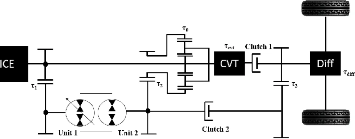
4.1 Comparison of different design transmission
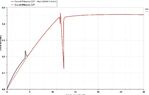
The analysis of the different types of layout was carried out in a first approximation considering a "mission test" with a single acceleration phase from 0 to the maximum vehicle speed of 30 km / h.
With this type of mission test (figure 31), it was possible to analyse the transmission behaviour in detail and in particular to evaluate the overall efficiency in the individual operating phases of the transmission, i.e. the negative circulating mode, the full mechanical point and the positive circulating mode.
Figure 32 shows the total efficiency of the CVT HM with hydraulic starting mode when the vehicle speed changes.
Figure 32 Overall efficiency of CVT HM with hydraulic starting mode
By analysing the performance trend, it is possible to highlight the transmission behaviour in the different phases:
• from 0 to 6 km / h the transmission works as if it were a pure hydraulic transmission.
• at 6 km / h there is a gear change. The gear change control opens the clutch on shaft 2 (figure 33 a) which will no longer transmit torque (figure 33 b), and closes the clutch on shaft 1. At this moment the transmission behaves like a CVT input coupled.
• from 6 km / h to 12 km / h the input coupled transmission works in negative circulating mode
• at 12 km / h there is a Full Mechanical Point, i.e. the area where the transmission reaches maximum efficiency. Figure 32 shows a sudden loss of performance close to the FMP. This is due to the reversal of rotation of the hydraulic motor and the model chosen for the losses in the hydraulic units. • from 12 km / h to 30 km / h the transmission works in positive circulating
mode
Figure 33 a) The model shows the shaft 2 with the clutch 2 relative to the pure hydraulic transmission, while the shaft 1 with the clutch 1 are related to the CVT
Figure 33 b) Clutch control signal on shaft 1 and shaft 2 of the transmission
To evaluate the effectiveness of the transmission model chosen, the CVT HM with hydraulic starting mode was compared first with a fully hydraulic transmission, and then with a CVT input coupled.
Figure 34 compares the total efficiency of the pure hydraulic transmission with the efficiency of the CVT HM with hydraulic starting mode.
Figure 34 Comparison of overall efficiency between pure hydraulic transmission and CVT with hydraulic starting mode
As can be seen from the comparison between the blue curve and the red curve, the CVT with HSM (hydraulic starting mode) transmission has a significantly higher performance, especially after shifting gears. This underlines that simple coupled CVT input has a significantly higher efficiency than pure hydraulic transmission, if high speeds are considered.
So analysing figure 34 it is easy to justify the use of the CVT HM compared to the pure hydraulic transmission, considering that for large stretches of the "mission test", and in particular close to the FMP area there is a greater difference in efficiency by 10%. This difference in performance justifies the use of an input coupled CVT transmission, which from a construction point of view presents greater complexity, especially when considering the use of the planetary gear and the complexity due to the transmission control.
Figure 35 Comparison of overall efficiency between pure hydraulic transmission and CVT input coupled
Analysing the trend of the efficiency curves in figure 35, it should be noted that for very low speeds (starting phase), i.e. in the case of negative circulating mode, the CVT input coupled has a lower efficiency than the pure hydraulic transmission. This aspect, which becomes much more interesting if an energy recovery is considered, justifies the use of a multi-range transmission, and in particular in the case examined, the use of a CVT HM with HSM.
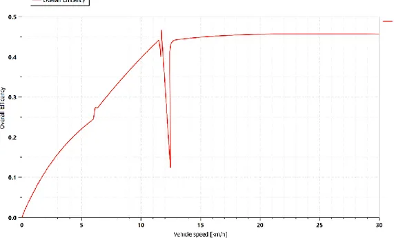
Figure 36 shows the comparison between the overall efficiency of the CVT input coupled and the efficiency of the CVT HM with HSM.
Figure 36 Comparison of overall efficiency between CVT with HSM and CVT input coupled
It should be noted that the efficiency of the CVT input coupled, for speeds between 5 km / h and 6 km / h (Vshift), has a higher efficiency than the CVT HM with HSM. As mentioned in paragraph 2.4, the choice of the Vshift was made considering the equality of the displacements of the hydraulic motor obtained from the design calculations. Nonetheless, considering the low displacements of the hydraulic units, it is possible to think of an optimization of the transmission, which can be obtained by changing the Vshift in order to maintain the efficiency of the CVT HM with HSM always greater than the total efficiency of the CVT input coupled. However, a greater displacement of the hydraulic motor may be required in the transmission starting phase, but this is justified by the improvement of the overall efficiency.
Figures 37 and 38 show the behaviour of the hydraulic units, as a function of the vehicle speed. By observing the fractional displacement of the hydraulic units
(figure37), as can be expected, is possible to notice that the pump decreases its displacement during the hydraulic starting phase, going from 0 to -0.4, the point where the gear change takes place. In this condition, as already mentioned, the CVT input coupled is engaged, i.e. the transmission will behave like a CVT input coupled. The pump displacement therefore, as for the CVT input coupled, moves from the minimum reached at Vshift (-0.4) to the zero displacement, the point where the transmission reaches the FMP. Continuing to accelerate, the vehicle goes into power split mode, and the pump displacement moves from zero to its maximum.
For this type of transmission, the displacement of the hydraulic motor remains constant throughout its operation.
Analysing the speeds of the hydraulic units (figure 38), it is possible to say that the behaviour between pump and motor is reversed, i.e. the rotation speed of the pump shaft remains constant at the maximum speed of 3500 rpm during transmission operation, while the hydraulic motor accelerates to the Vshift (gear shift), then decelerates until it reaches zero speed (FMP). At this point when the vehicle accelerates, it switches in power split mode and the hydraulic motor reverses its direction of rotation, reaching the maximum speed of 3500 rpm.
Figure 37 Fractional displacement of hydraulic units
4.2 Gear change optimization
As mentioned in the previous paragraph, the variation of the V Shift involves the variation of the displacements of the hydraulic machines and of the transmission ratio of the shaft 2 relative to the pure hydraulic transmission. In particular, decreasing the change speed also decreases the contribution due to the hydraulic motor (considering the pure hydraulic transmission) and therefore the displacement required. However, by decreasing the change speed, the CVT will engage earlier than in the case where Vshift was equal to 6 km / h. This means that the displacement required by the hydraulic motor in the case of CVT increases considerably. Having to consider the higher displacement, or that required by the CVT, there will be an increase in the displacement of the hydraulic motor of about 10 cc. This however does not represent a worsening in terms of costs and size, if we consider the improvement in the overall efficiency of the transmission, as shown in figure 39.
Figure 39 Comparison of overall efficiency between CVT with HSM and CVT input coupled, with Vshift equal to 4 km/h
Considering figures 39 and 40, obtained respectively for Vshift equal to 4 km / h and 2 km / h, it is noted that in both cases efficiency has improved. However, choosing a Vshift equal to 2 km / h means doubling the displacement of the hydraulic motor, and obtaining a speed range in which the efficiency of the CVT HM with HSM is greater than the CVT input coupled, lower than in the case in figure 39.
Figure 40 Comparison of overall efficiency between CVT with HSM and CVT input coupled, with Vshift equal to 2 km/h
4.3 Constant power simulation
By applying a mechanical brake to the transmission (figure 41), it was possible to test the overall efficiency at constant power.
Figure 41 scheme of mechanical brake
As the graph in Figure 42 shows, the efficiency at full load of the transmission reaches a maximum of about 83% at the full mechanical point, and decreases up to 75% which is reached at maximum vehicle speed.
It can be seen that even for partial load, the efficiency remains fairly high. For a partial load of 50% the overall efficiency reaches approximately 75%. However, in this case, analysing the trend of the yellow curve, it is noted that the curve maintains a non-constant trend, losing greater efficiency at maximum speed (50%). This result shows, however, that even for partial load, the CVT HM with HSM transmission maintains overall good efficiency.
Figure 42 Overall transmission efficiency with partial load of 50%, 75% and 100%.
4.4 WLTC (Worldwide harmonized Light-duty vehicles
Test Cycles)
Not having available data regarding the real work cycle of the street sweeper, in order to evaluate the transmission performance on a real cycle, the WLTC model (figure 43 a) was used, adapting it to the type of vehicle. WLTC is a procedure based on new driving cycles to test the average fuel consumption, CO2 emissions and pollutant emissions of passenger cars and light commercial vehicles. The WLTC is divided into different classes according to the maximum speed that can be reached by the vehicle. In our case (figure 43 b) the test cycle for class 1 (vehicle up to 60 km / h) has been adapted.
Figure 43 a) WLTC class 1
Figure 43 b) Mission profile based on the WLTC, adapted to the characteristics of the street sweeper
Analysing the transmission efficiency on the mission profile based on the WLTC (figure 44), it should be noted that the average transmission efficiency stands at very low values, around 40% -45%. The peaks that exceed the efficiency are transients due to the gear change, and in particular at the moment in which clutch 1 opens and clutch 2 closes, that weren’t modelled in the analysis.
Figure 44 Overall transmission efficiency during WLTC mission profile
This behaviour shows that the hydraulic units work at low efficiencies throughout the WLTC cycle, and in particular as can be seen from figure 45 with low hydro-mechanical efficiency.
To better understand the reason behind this behaviour, the amount of power absorbed by the transmission throughout the cycle was analysed.
Figure 45 Hydro-mechanical pump efficiency
As can be seen from figure 46, the average power absorbed by the transmission during the WLTC cycle is approximately 6-7 kW, much less than the 25 kW potentially deliverable by the ICE. Therefore, working at low power, compared to the one for which the transmission was designed and sized, the hydraulic machines are oversized and therefore work at low efficiency.
Figure 46 Power absorbed by CVT HM with HSM during the mission cycle
A further optimization could be achieved by dimensioning the transmission with 10-12 kW of ICE power, taking into account the part of power absorbed by the secondary users (brushes, etc.).
4.5 Simulation of energy recovery system
Figure 47 shows the transmission scheme with the energy recovery system. the ability to recover energy during the braking phase of the vehicle was tested in a class 1 WTLC.
Figure 47 Scheme of Continuously Variable Hydro-Mechanical Transmission with Hydraulic Starting Mode and Energy Recovery System
![Figure 15 Diagram of the phase of positive recirculating mode transmission input coupled [14]](https://thumb-eu.123doks.com/thumbv2/123dokorg/4574628.38434/27.774.128.644.209.402/figure-diagram-phase-positive-recirculating-transmission-input-coupled.webp)