a.a. 2008/2011
Università degli Studi di Catania
Scuola Superiore di Catania
International PhD
in
ENERGY
XXIV cycle
New technologies for energy savings
in the refurbishment of existing buildings
Maria Novella Papa
Coordinator of PhD
Tutor
3
Acknowledgements
I would express my thanks to the people who have given me their support during the writing of this thesis and during all the Ph.D. course.
Firstly I thank my Ph.D. Tutor Prof. Luigi Marletta for his encouragement to start this activity and for his great efforts to solve clearly and simply my many doubts.
Then I would thank my Ph.D. Coordinator Prof. Alfio Consoli who has constantly followed the research activity urging to do better and giving useful advices.
I'm also grateful to the Ph.D. researchers Fabio Sicurella and Gianpiero Evola for their support with writing e-mails, giving wise advices and answering my numerous questions.
I would also express my gratitude to Etienne Wurtz, Research Director of CNRS-INES, who gave me the opportunity to carry out a part of my research activity at the INES laboratories in Chambéry.
My sincere thanks to my colleagues with whom I shared not only study experiences but also many pleasant time.
I'm also very grateful to the staff of Scuola Superiore, especially to Dr. Bice Immè for assisting me many times with kindness.
Finally I would express my most important thanks to my family: my dear parents and my brother, for their loving support and a special thank to my beloved Mario for his encouragement, understanding and great patience.
4
Contents
Introduction 7
PART I 1. Energy Performance of building. 11
1.1. State of the art. 11
1.2. Regulations about Energy Performance of Buildings. 12
1.3. Methodology for calculation of Energy Performance. 14
2. Indoor Thermal Comfort 17
2.1. An overview on indoor thermal comfort. 17
2.2. The indoor thermal comfort indicators. 20
3. Thermal energy storage methods 23
2.1. Sensible heat storage. 23
2.2. Latent heat storage. 24
4. Phase Change Materials (PCMs) 27
4.1. Properties of PCM. 27 4.1.1. Thermal Properties. 27 4.1.2. Physical Properties. 28 4.1.3. Kinetic Properties. 28 4.1.4. Chemical Properties. 30 4.2. Classification of PCM. 30 4.2.1. Organic substances. 31 4.2.2. Inorganic substances. 33 4.2.3. Eutectics susbstances. 34 4.3. Commercial Products. 36
4.4. Application of PCMs in a building system. 37
4.4.1. Active PCM systems. 38
5
PART II
5. The simulation tools 41
5.1. Structure of EnergyPlus. 41
5.2. EnergyPlus calculation methodologies. 43
5.2.1. Conduction Transfer Function. 44
5.2.2. Conduction Finite Difference. 48
5.3. Setting an EnergyPlus simulation. 51
6. The simulation phase 53
6.1. Preliminary activities. 53
6.1.1. The experimental set-up. 54
6.1.2. The characterization of the Phase Change Material. 57
6.2. PCM simulations with EnergyPlus 58
7. The case study 61
7.1. The building model 61
7.2. Composition of building elements. 64
7.2.1. Exterior wall. 64
7.2.2. Interior partition without PCM. 64
7.2.3. Ceiling and Floor. 64
7.2.4. Window. 65
7.2.5. PCM system. 65
7.3. Output parameters of the simulations. 66
8. Case a 69
8.1. Base case. 69
8.2. Results of case a.1. 75
8.3. Results of case a.2. 86
9. Case b 93
9.1. Base case. 93
6
9.3. Results of case b.2. 109
Conclusions 113 References 116
7
Abstract
The building sector is responsible for many environmental problems mainly
because of the energy consumptions for heating, cooling, lighting, .... during the whole life cycle of a building.
The refurbishment of the existing building stock offers an opportunity to take effective and environmentally friendly solutions.
A thermal energy storage system is very effective item to reduce the energy
consumptions because it allows the possibility of using solar energy continuously, reducing the internal temperature fluctuation and improving the thermal comfort.
The most used heat storage materials for building application are the Phase Change Materials (PCMs) which store solar energy during the day and release it during the night.
The aim of this work is to test the usefulness of PCMs for improving summer thermal comfort in lightweight buildings. In order to evaluate the performance of PCMs we carried out simulations using EnergyPlus, a building simulation tool based on the finite difference method.
For the assessment of the optimal thermal comfort conditions we considered the adaptive comfort method and we introduced some new thermal comfort indicators.
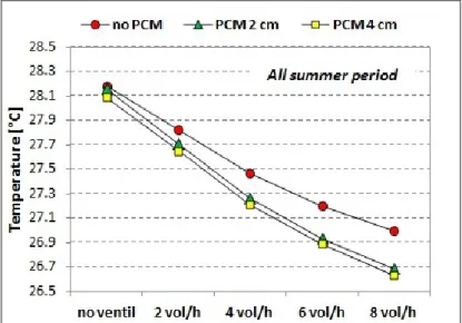
The results of simulations show a very significant effect of PCMs during the summer season. In particular the application of a PCM panel with a ventilated air gap proves to be beneficial for the indoor thermal comfort, due to a consistent decrease of the air temperature fluctuations and the reduction of the maximum operative temperature without using any cooling system.
The present work is intended to give a contribution to optimize building components incorporating PCMs for thermal storage, in an energy savings and thermal comfort perspective.
8
Introduction
The importance of energy use in buildings is a topic widely covered and studied; many policies and regulations have been introduced in order to reduce the energy consumption and improve the energy efficiency.
The energy consumption is produced mainly by the residential and tertiary sector, which is responsible for about 40% of the total final energy demand. In particular in the EU residential sector, more than 50% of the total final energy consumption is used for space heating, 25% for domestic hot water and 11% for electricity. As a result, it is one of the sectors with the highest potential for improvement. In this case the improvement may involve both the building envelope and the energy technologies at the building service (heating , cooling, lighting, etc...).
A new and attractive system for space heating and cooling of buildings is based on thermal energy storage which allows the possibility of using solar energy continuously, storing solar energy during the day and releasing it during the night reducing the internal temperature fluctuation and improving the thermal comfort sensation.
The storage of thermal energy can be done in relation to the sensible and latent heat. Sensible heat storage means are standard materials such as concrete, brick, plaster, etc.... which need a heavy mass for storing thermal energy; contrariwise latent heat storage materials are more advantageous because they have a large energy storage capacity associated with a very small thickness (few centimeters). In the latent heat thermal energy storage, the most used materials are Phase Change Materials (PCMs), like paraffin wax and hydrate salts, due to a larger storage density compared to sensible heat storage materials.
In fact, an ideal material without phase change, i.e. the standard construction materials, heats up when the heat is stored and cools down when the heat is released. A phase change material stores a large amount of thermal energy during its melting phase without changing its temperature and, when the phase change is completed, the temperature starts rising.
Besides, a standard material such as concrete may cause larger fluctuations of indoor temperature, while the PCMs provide large latent heat storage over the
9 narrow range of temperatures typically encountered in buildings, thus they can improve the thermal comfort level.
In the last years the PCMs are becoming very attractive and required materials for building application due to their possibility to be easily compounded with common building materials and manufactured into various composite building elements and components, such as laminated boards or panels. Particularly these last ones are very suitable to be incorporated into the envelope in the case of building refurbishment because they can be easily installed and differently arranged. However, the latent heat storage in buildings and even the PCMs induced many investigations in the last decades because there are still several difficulties concerning some practical issues. So, more surveys are still required on these field to apply this concept in a reliable and practical way.
This research activity wants to provide new assessments on PCMs efficacy on the summer indoor thermal comfort in the case of application for building refurbishment.
The project consists of two main parts: the first is an overview on important topics related to the research activity, such us the Energy Performance Directives in the building sector, the indoor thermal comfort, the thermal energy storage methods, the various typologies, properties and application systems of the phase change materials.
In the second part, we carried out numerical simulations with the software tool EnergyPlus which allows the building energy analysis and its thermal load simulation taking into account the building's physical description (location, materials, construction, etc...). By varying the thickness of the PCM panel, embedded in the internal partitions of a test building, as well as the intensity of the night mechanical ventilation, some interesting results arise as far as thermal comfort is concerned.
The analysis is supported by new indicators, which help quantify the intensity and the duration of the potential thermal discomfort as well as the actual duration of PCM activation phase.
The main goal of this research work is to demonstrate how the PCM are helpful for energy savings in the building sector by reducing operational energy
10 consumptions during the summer period and realizing an effective solution for the improvement of the building thermal comfort.
11
PART I
1. Energy Performance of building.
1.1. State of the art.
The problem of energy efficiency of buildings has been at the centre of a broad scientific and technical debate in the last years; in fact the building sector is responsible for many environmental problems because of the exploitation of non-renewable resources, the use of soil and the energy consumptions during the whole life cycle of a building.
Consequently, an increase of building energy performance can constitute an important instrument in the efforts to alleviate the EU energy import dependency and help to comply with the Kyoto Protocol to reduce carbon dioxide emissions. The new European Directive 2010/31/EC on the Energy Performance of Building (EPBD), which replaces the Directive 2002/91/EC, is also aimed at energy conservation and at improvement of energy efficiency of buildings.
In fact, given the long life-span of buildings (50 to more than 100 years) and the high number of existing buildings, it is clear that the largest potential for energy conservation measures is related to the existing building stock; in fact about 70% of the residential buildings are over 30 years old and about 35% are more than 50 years old. Also, considering that most national building regulations concerning the thermal insulation of building envelopes were introduced after the 1970s following the energy crisis and the ageing technical installations (it is estimated that about 10 million residential boilers are older than 20 years old), we can understand how much the thermal performance of the old building is low.
Most energy consumption in existing building sector is due to the heating, lighting and cooling, and also an increasing percentage is consumed by domestic appliances, computers and other electrical equipment.
So, changes and innovations of materials, elements, systems... and new installations could give a good contribute to the reduction of energy needs.
The refurbishment of the existing building stock offers an opportunity to take cost-effective measures and make them efficient and environmentally friendly, with an
12 increased social and financial value. Similar opportunities may exist even during building renovations (i.e. repairs and restorations to good condition). Protecting the architectural heritage is a primary benefit, but it may also be financially attractive.
In many cases, building refurbishment costs are lower (even for high investment retrofit operations) than demolition and reconstruction costs (about half to one-third of the cost). In light of sustainability it makes more sense than ever to renovate or refurbish old buildings.
Several efforts have been made by the EU Member States to develop methodologies and software tools in order to enable architects and engineers during their decision-making process for building refurbishment.
A number of decision support softwares have been developed in the framework of European projects over the past few years, for the assessment of different scenarios during renovation or refurbishment of buildings.
Due to the rapid increase in the living standard together with climate changes and economic development, the growing trend of energy use in buildings might be continuously experienced in the future. Promoting energy efficiency and conservation in buildings is therefore becoming one of major issues of concern to governments and society today.
1.2. Regulations about Energy Performance of Buildings.
The European Directive 2010/31/EC on the Energy Performance of Buildings (EPBD) requires that an energy performance certificate is made available when buildings are constructed, sold or rented out. The certificate has to express the energy performance (EP) of the building and it has to be accompanied by recommendations for the cost effective improvement of the energy performance. The calculation of the energy performance should be carried out according to a methodology based on a general framework set out by the EPBD.
The "energy performance of a building" is defined as ‘the amount of energy actually
consumed or estimated to meet the different needs associated with a standardized use of the building’. This amount shall be reflected in one or more numeric
13 - insulation,
- technical and installation characteristics,
- design and positioning in relation to climatic aspects, solar exposure and influence of nearby structures,
- own-energy generation,
- other factors, including indoor climate, that influence the energy demand.
The European Energy Performance Directive has the aim of promoting the reduction of carbon dioxide emissions, according to the limits established in the Kyoto Protocol. In order to reach this target each State of European Union must to provide regulations to improve energy performance of buildings (e.g. Italy transposed the EPBD through Legislative Decree n. 192/2005 then updated by the Legislative Decree n. 311/2006 and the following Decree n. 54/2009 concerning the National guide lines for building energy certification).
However, actions provided by any regulation are the following:
- adoption and application of a methodology to evaluate the energy performance of buildings (i.e. primary energy use for heating, cooling, ventilation, hot water supply and lighting);
- the adoption of the necessary measures to ensure the minimum amount of energy for building requirements;
- the integration with technologies producing energy from renewable sources; - the adoption of an energy certificate that includes reference values and
recommendations for the improvement of the energy performance of building; - the adoption of measures to establish a regular inspection of boilers and
air-conditioning systems.
The Directive 2010/31/EC, notably in accordance with article 1, "promotes the improvement of the energy performance of buildings within the Union, taking into account outdoor climatic and local conditions, as well as indoor climate requirements and cost-effectiveness".
In particularly the new Directive provides requirements about:
- the methodology for calculating the energy performance of buildings and building units;
- the application of minimum requirements to the energy performance of new buildings and new building units;
14 - the energy certification of buildings and building units;
- independent control systems for energy performance certificates and inspection reports of heating and air-conditioning systems in buildings;
- national plans for increasing the number of nearly zero- energy buildings.
The European member states must define a methodology for calculating the energy performance of buildings in accordance with the criteria set out in Annex I "Common general framework for the calculation of energy performance of buildings". Besides the Directive establishes that, in order to contain the energy demand, each member states have to define the requirements for technical building systems in respect of:
- the overall energy performance, - the proper installation and sizing, - the appropriate regulation and control.
So, according with the requirements of the new European Directive and considering the great importance of the building sector in the field of energy savings, the refurbishment of existing buildings assumes a very important role and represents a good opportunity to satisfy the legislative prescriptions.
1.3. Methodology for calculation of Energy Performance.
The European Directive prescribes that EU Member States shall apply a methodology at national or regional level, for calculation of the energy performance of buildings on the basis of a general framework.
Some European regulations define the methodologies to calculate the energy performance of buildings and for evaluation of building energy flows:
- European Standard EN ISO 15603 proposes different energy rating methods; - European Standard EN ISO 13790 provides the methodology for calculation of energy use for space heating and cooling;
- European Standard EN 15316 defines how to use renewable energy sources and other methods in order to generate space heating and product warm water.
Many Italian norms (expressed through the acronym UNI) about energy in building consist of the adoption or transposition of European (EN) and/or International (ISO) standards. Italy transposed the regulations mentioned above through a new
15 set of norms called UNI TS 11300 to calculate the energy performances of building. These norms are the following:
- Technical Sheet UNI/TS 11300:1 for evaluation of energy need for space heating and cooling;
- Technical Sheet UNI/TS 11300:2 for evaluation of primary energy need and of system efficiencies for space heating and domestic hot water production;
- Technical Sheet UNI/TS 11300:3 for evaluation of primary energy need and system efficiencies for space cooling;
- Technical Sheet UNI/TS 11300:4 for using of renewable energy sources and of other technologies for space heating and domestic hot water production.
Every methodology shall include at least the following aspects: thermal characteristics of the building (envelope and internal partitions, etc.) and these characteristics may also include air-tightness; heating installation and hot water supply, including their insulation characteristics; air-conditioning installation; ventilation systems; built-in lighting installation (mainly the non-residential sector); position and orientation of buildings; passive solar systems and solar protection; natural ventilation; indoor climatic conditions including the designed indoor climate.
In this calculation other positive and relevant aspects shall be taken into account, like active solar systems and other heating and electricity systems based on renewable energy sources; electricity produced by CHP (Combined Heat and Power); district heating and cooling systems; natural lighting.
The energy certification of buildings requires a method that is applicable both to new buildings and to the existing ones, focusing attention more on building features than on their management. Many studies have been developed on energy ratings, by creating and applying methods to predict annual building energy costs, to evaluate the quality of the given results and the process, to establish energy benchmark values and to plan energy efficiency improvements of the building stock.
The main inputs needed for this standard are the followings: the transmission and the ventilation properties; the heat gains from internal heat sources; the solar and climatic data; the description of the whole building and its components, systems and uses; the comfort requirements (set-point temperatures and ventilation rates);
16 the length of the heating and cooling seasons; the data related to the heating, cooling, hot water, ventilation and lighting systems; the partition of building into different thermal zones for the calculation (different systems may require different zones); the energy losses dissipated and recoverable or recovered in the building; the air flow rate and temperature of ventilation supply air.
The main outputs of the standard calculation methodology are the annual energy needs for space heating and cooling, the annual energy needs for hot water, the annual primary energy consumption. Other outputs are the monthly values of energy needs and energy use and monthly values of the main elements in the energy balance such as. the transmission heat losses, the ventilation heat losses, the internal heat gains, the solar heat gains. Additional outputs are the contribution of passive solar gains and system losses (from heating, cooling, hot water, ventilation and lighting systems) recovered in the building.
17
2. Indoor Thermal Comfort
2.1. An overview on indoor thermal comfort.
The first recognized model for thermal comfort was proposed by Fanger about thirty years ago and it had a wide scientific consensus so that it was included, several years later, in the ISO Standard 7730 (ISO, 1994). Fanger's method introduced two comfort indicators the PMV (Predicted Mean Vote) and the PPD (Predicted Percentage of Dissatisfied); the first index is obtained combining four physical variables (air temperature, air velocity, mean radiant temperature and relative humidity) and two personal variables (clothing insulation and activity level). The index provides a score that corresponds to the ASHRAE thermal sensation scale and represents the average thermal sensation felt by a large group of people in a space. The second index is calculated from PMV and predicts the percentage of people who are likely to be dissatisfied with a given thermal environment. The PMV and PPD can be represented by a function where the percentage of dissatisfied increases for PMV values above and below zero (thermally neutral).
However it is important to note some considerations with respect to this method: the PMV model is designed to predict the average thermal sensation for a large group of people but it also implies that not all occupants are thermally satisfied; in fact the PMV is an index based on thermal sensation, so the evaluation can be
18
different from an occupant to another. Besides this model has been developed
considering a building under controlled micro-climate condition, so it cannot manage transient situation that occurs, for instance, in naturally ventilated buildings, in buildings without HVAC systems or where occupants vary their behaviour and activity. This means that, for most of bioclimatic buildings as well as for a large number of renovating buildings, the Fanger’s approach cannot be undertaken.
So in the above mentioned cases it is possible to consider another thermal comfort approach, proposed by Nicol and Humphreys and called "adaptive comfort".
The adaptive model is based on the following principle: "If a change occurs such as
to produce discomfort, people react in ways which tend to restore their comfort"
(Humphreys). This principle states that people have the capability to adapt themselves to the climate conditions of an environment in order to achieve their well being conditions; besides it allows to relate the comfort sensation to people's action and to define a "comfort temperature", that is the result of the interaction between the occupants and the building considering the climate conditions. So, it signifies that the operative temperature is continually changing and the rate and time of these changes can significantly affect the indoor thermal comfort conditions.
For example, occupants of naturally ventilated buildings have the possibility to increase the air velocity in the room by operating windows and, doing this, they can still create a comfortable environment in higher indoor temperatures having a direct contact to the weather outside. While Fanger’s PMV-model can only take the effects of behavioral adaptation into account: the adjustment of clothing and the level of activity or the regulations of the air velocity through the HVAC system. Therefore this model is only truly appropriate for sealed air-conditioned buildings. In a number of studies on the adaptive comfort approach it is demonstrated that the comfort temperatures and clothing insulation are more strongly correlated to
the ‘running mean outdoor temperature’ (ϴrm) than to the actual or mean outdoor
temperature during the day. This implies that not only today’s weather but also the weather of the past few days has influence on the clothing values and the perception of comfort temperature.
19 The running mean outdoor temperature is an exponentially weighted mean outdoor temperature and is expressed by the equation:
1
4 ...
3 3 2 2 1 rm
ed
ed
ed
ed (1) where: rm
is the external running mean temperatures [°C]1
ed is the daily mean external temperature for the previous day [°C]2
ed is the daily mean external temperature for the day before and so on [°C]α is a constant between 0 and 1 (the recommended value is 0.8)
The importance of the adaptive approach increased in the last ten years, so that it was first included in the ASHRAE Standard 55 and more recently in the EN Standard 15251. These standards provide the method for determining acceptable thermal conditions for buildings without mechanical cooling systems. Particularly the Annex A of the EN Standard 15251 reports the summer temperature limits for design buildings with an air-conditioned system and without a mechanical cooling system (this last typology is the one that we took into account for the case-study considered in this work).
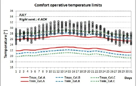
20 These limits are calculated as a function of the ϴrm and allow to define three comfort categories: I,II and III. The class II represents a situation which could generally be considered acceptable; the other two classes around class II refer to an extra high quality building (class I) or a building with an indoor climate that is less acceptable as such (class III).
For each type of building or space, the Standard EN 15251 recommends a specific design value of the indoor temperature of the building and HVAC systems; in particular for buildings without mechanical cooling systems the acceptable indoor temperatures are defined by the following functions:
Category I imax 0.33rm 18.82 2 8 . 18 33 . 0 min i rm Category II imax 0.33rm 18.83 (2) 3 8 . 18 33 . 0 min i rm
Category III imax 0.33rm 18.84 4 8 . 18 33 . 0 min i rm
2.2. The indoor thermal comfort indicators.
For a free running building where no HVAC system controls the microclimatic conditions, it is necessary to define some indicators which take into account the most important physical parameters for thermal comfort i.e. the operative temperature. In the following we introduce some new indicators defined on the basis of the operative temperature and which can help in the assessment of the optimal thermal comfort conditions for an indoor environment.
- Frequency of the monthly thermal comfort conditions (FMTC), represents the time fraction within a month during which temperatures are falling in the comfort/discomfort thermal ranges. Temperature values delimiting the three ranges are the following:
21 • Tunder as lower limit
When the operative temperature is over the upper limit, the risk of hot sensation occurs; on the contrary if the operative temperature is below the lower limit the risk of cold sensation occurs. When operative temperature falls within the range Tunder<Top <Tover the thermal comfort condition occurs.
For most of practical applications the upper and the lower limit can be assumed as constant values, such as:
Tover = 27 °C Tunder = 22 °C
But for more accurate comfort estimation, these limits should vary according the variations of the running mean outdoor temperature as defined previously in § 2.1. In the present work we considered this last calculation method.
- Intensity of thermal discomfort (ITD) is the sum, during a month, of the degrees of temperature that exceed the upper limit of comfort temperature or that fall
below of the lower limit of comfort . It is defined as follows:
ITD
T
t
T
dt
year over over
(3)ITD
T
t
T
dt
year under under
' ' (4) where:T(t)-Tover = T(t)-Tover if T(t) > Tover otherwise is equal to 0 T(t)-Tunder = T(t)-Tunder if T(t) < Tunder otherwise is equal to 0
The two parameters describe the indoor discomfort sensation felt by the occupants in the building during the winter and the summer season.
When the indoor environment of a building without HVAC system is characterized by the condition ITDover ≈ ITDunder ≈ 0, it means that the indoor temperature are falling in the comfort range all year without heating or cooling.
22
Fig. 3 The Intensity of discomfort parameters for winter and summer period.
23
3. Thermal energy storage methods
The energy storage plays an important role in conserving the energy because it could alleviate the mismatch between supply and demand but also could improve the performance and reliability of energy systems. Besides, it leads to saving of premium fuels and makes the system more cost effective by reducing the wastage of energy and capital cost.
Energy can be stored according different forms, such as mechanical, electrical, thermal and chemical. In particular in this work we are going to consider the storage of thermal energy.
Thermal energy can be stored as a change in internal energy of a material as sensible heat or latent heat.
2.1. Sensible heat storage
The sensible heat storage (SHS) consists in storing the thermal energy by raising the temperature of a solid or liquid (Fig. 4). In a sensible thermal energy storage system, energy is stored by changing the temperature of the storage medium.
Fig. 4 Comparison of thermal energy stored by a Sensible Heat Storage (SHS) and a Latent Heat Storage (LHS).
24 This storage method is based on the heat capacity of the material and on the difference of temperature during the process of charging and discharging.
The amount of heat stored is defined by the following equation:
) ( o i p To Ti pdT mC T T mC Q
(5)The thermal energy stored is proportional to the difference between the storage
input and output temperatures (Ti and To), the mass of the material used as storage
medium (m)and its heat capacity (Cp).
The highest sensible heat storage capacity belongs to the water which represents the best sensible heat storage material. Other selected solid or liquid materials such as construction materials (concrete, rock and brick) have a minor heat storage capacity; whereas organic liquid substances (ethanol, proponal, butanol, octane,...), molten salts and oils have a fairly high heat capacity and a temperature range above 100°C (Tab. 1).
2.2. Latent heat storage
The latent heat storage (LHS) is an energy storage method which allows to store a larger amount of energy than a sensible heat storage (see Fig. 4) because the
25 charge of thermal energy occurs at a constant temperature; so it could be very suitable and advantageous for solar energy applications, for instance.
Latent heat storage can occur through solid-liquid, liquid-gas and solid-gas phase transformations but considering the building application the first ones are the most suitable because of their feasibility and effectiveness.
In fact although liquid-gas and solid-gas transition have higher latent heat of fusion, they can cause some practical problems relating to their large volume changes on phase transition and lose a large part of their potential utility in thermal storage systems because the system becomes complex and impractical.
In particular, in this work we'll analyze latent heat storage systems realized with storage material which make a phase change from solid to liquid and vice–versa. The storage capacity of the LHS system with a storage material is given by the following equation:
Tm
Ti To Tm lp spT
dT
m
h
mC
T
dT
mC
Q
(6) Where:m = mass of heat storage medium [kg]
Csp = specific heat in the solid phase [J/kgK] Clp = specific heat in the liquid phase [J/kgK] h = heat of fusion per unit mass [J/kg] Ti = initial temperature [°C]
Tm = melting temperature [°C]
Tf = final temperature [°C]
In the latent heat storage system the thermal energy is charged when the material achieves its melting temperature (solid to liquid phase) and it is discharged when material temperature decreases (liquid to solid phase). A latent storage material could store 5–14 times more heat per unit volume than a sensible storage material such as water, masonry, or rock.
26 Very effective latent heat storage materials are Phase Change Materials (PCMs) which are known to melt with a heat of fusion in any required range. However, for their employment as latent heat storage materials, it is necessary to know their thermodynamic, kinetic and chemical properties.
27
4. Phase Change Materials (PCMs)
4.1. Properties of PCM
Due to their application as a thermal storage material, the PCMs are characterized by many interesting properties that we can classify in four main groups:
Thermal properties Physical properties Kinetic properties Chemical properties
As a single material can't have all the required properties to be an ideal thermal storage media, it is possible to add others substances in order to make up for the missing properties or optimize the existing ones. For example, metallic fins can be used to increase the thermal conductivity of PCMs (as we shall see), super-cooling (see § 4.1.3) may be suppressed by introducing a nucleating agent in the storage material, and incongruent melting can be inhibited by the use of a PCM of suitable thickness.
Furthermore some economic considerations should be taken into account in order to carry out a wider and more complete survey, but this topic is not covered in this work.
4.1.1. Thermal Properties.
The most obvious thermal properties for a PCM for building application is a suitable phase change temperature and a high latent heat of transition. The first requirement is very important to ensure an effective charge and discharge cycle; the choice of the melting temperature depends on the PCM application and, above of all, on the weather conditions of the building location.
For a given climate condition and building, if the melting temperature is too high, PCM can't fully achieve its working phase and the amount of the stored heat will be too low in the daytime; on the contrary, if the melting temperature is too low, the
28 PCM can't carry out completely its charge-discharge cycle and it could remain in the same phase.
As concerns to the second property, the latent heat should be as high as possible, in order to reduce the container size.
As well as the latent heat, the thermal conductivity of a PCM should be quite high in order to ensure a better heat transfer within the material and so a more effective charge and discharge cycle.
4.1.2. Physical Properties.
The small volume variation during the phase transformation is one of the main physical characteristics of a PCM for building application; in fact smaller changes in volume can reduce the containment problems and consequently make it possible the application of a phase change medium with a smaller thickness.
Others physical properties which can make more desirable a PCM for thermal energy systems are a high density (the higher the density the larger is the quantity of the latent heat stored) and a low vapor pressure at operating temperatures in order to reduce the mechanical stability on a medium containing the PCMs.
4.1.3. Kinetic Properties.
The kinetic properties are related to the mechanism of the phase transition. In particular the kinetic properties required for a PCM are:
- a little or no supercooling during the cooling phase - high rate of crystal growth (nucleation rate)
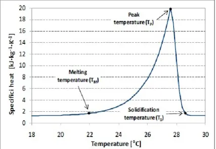
The supercooling (also called subcooling) is the effect during which a temperature significantly below the melting temperature is reached until a material begins to solidify and release heat. If that temperature is not reached, the PCM will not solidify at all and thus it only stores sensible heat. The Fig. 5 shows the effects of subcooling on heat storage.
During the phase transition from liquid to solid state, the latent heat is not released when the melting temperature is reached due to subcooling.
29 The effect of subcooling makes it necessary to reduce the temperature well below the phase change temperature to start crystallization and to release the latent heat
stored in the material. If nucleation1 does not happen at all, the latent heat is not
released at all and the material only stores sensible heat.
The PCMs, in particular salt hydrates, have the tendency to supercool and not melt in a congruent way; so this can cause some segregation problems, i.e the components of the PCM with different composition are separated from each other macroscopically and the those ones with a composition different from the correct initial composition optimized for heat storage then show a significantly lower capacity to store heat.
This process can have some important and also deleterius effects on the overall characteristics of PCMs and affects their effectivness in storing heat.
In order to prevent segregation problems and to enhance the nucleation rate some
nucleasting and thickening agents 2 are added to PCM compounds.
1
The nucleation is the initial process that occurs in the formation of a crystal from a solution (liquid or vapour) in which a small number of molecules become arranged in a pattern characteristic of a crystalline solid forming a site upon which additional particles are deposited as the crystal grows.
2 Thickening means the addition of a material to the PCM to increases its viscosity. Due to the high
viscosity, different phases cannot separate far until finally the whole PCM is solid.
Fig. 5 Effect of little subcooling and nucleation on heat storage (left) and effect of a large subcooling without nucleation.
30
4.1.4. Chemical Properties
Regarding the chemical properties, PCM should be: - chemical stable,
- compatible with the construction materials, - non-degradable after melt/freeze cycles, - non-toxic, non-flammable, non-explosive.
The chemical stability of the PCM can ensure a long lifetime of the material especially when it works in difficult conditions (exposition to high temperatures, gases, radiation,...).
The cyclic stability means that the phase change has to be reproducible, i.e. the use of the material many times for storage and release of heat as required by an application. The number of cycles varies from only one, when the PCM is used for heat protection in the case of a fire, to several thousand cycles when it is used for heating or cooling of buildings. This property depends on the phase separation (see § 4.1.3) which can change the initial PCM composition and reduce over time the effectivness of the heat capacity.
4.2. Classification of PCM
The first classification of phase change materials is probably made by Steiner et al. in 1980. Then several publications could be mentioned: Abhat in 1983 (Fig. 6), Lane in 1983 and in 1986, and recently Hiebler and Mehling 2001, Zalba et al. 2003, Sharma et al. 2004, Farid et al. 2004, and Kenisarin and Mahkamov 2007.
31 Considering the PCM based on latent heat storage, it is possible to account three most important classes: organic, inorganic and eutectics compounds.
Organic materials, like paraffins, alkane mixtures, fatty acids and their derivatives, are mostly used for many applications in the field of energy conservation in building; while inorganic compounds (especially hydrate salts) cover a wider temperature range than organic materials and have a higher enthalpy per volume due to their higher density. The inorganic PCM are mostly considered for solar energy storage in tanks.
At present, most of the commercial phase change materials suitable for building construction are paraffins and hydrate salts. The inorganic PCMs are much cheaper than the organic ones, but these last ones could cause some leakage problems in the solid-liquid phase change. So they are less suitable to be used in building envelope.
PCMs eutectics are commonly organic-organic, organic-inorganic and inorganic-inorganic compounds.
4.2.1. Organic substances.
The most known and used organic materials for energy storage application are the paraffins and the non-paraffins.
The common paraffins (of type CnH2n+2) belong to the family of saturated
hydrocarbons; they consist of mainly straight chain hydrocarbons which have a melting temperature between 23 - 67 °C (Abhat 1983) and, during the crystallization of the (CH3) chain, they release a large amount of latent heat. Paraffins between C5 and C15 are liquids and the rest are waxy solids. These last ones are the most-used commercial organic PCMs.
Commercial-grade paraffin wax is obtained from petroleum distillation and is not a pure substance, but a combination of different hydrocarbons. In general, the longer the average length of the hydrocarbon chain, the higher the melting temperature and heat of fusion.
The paraffin waxes represent very suitable materials for thermal energy storage applications especially in the building sector thanks to their several properties: a quite wide melting temperature range, the safety, the reliability, the
non-32 corrosivity, the chemical inertia, the stability below a certain temperature, etc... Besides they show little volume changes on melting and have low vapor pressure in the melt form. For these properties, the system that uses paraffins usually has very long freeze–melt cycle.
However, these materials present some drawbacks, such as the low thermal conductivity and a moderately flammability, but all these undesirable effects can be partly eliminated by slightly modifying the wax and the storage unit.
The non-paraffin materials (such as fatty acids, alcohols and glycols) are more numerous than paraffin materials. In spite of these last ones, which have similar properties, each non-paraffin material have its own properties. Some properties of these materials are as follows: high heat of fusion, inflammability, low thermal conductivity, low flash points, varying level of toxicity and instability at high temperatures.
33 The larger group of non-paraffin compounds is represented by the fatty-acids
which have the following chemical formula: CH3(CH2)2nCOOH. The fatty acids
realize sharper phase change transformations than paraffin materials but, in spite of them, their cost is much higher; in fact they are 2–3 times more expensive than the technical grade paraffin’s.
The table 2 shows some organic materials and their properties.
4.2.2. Inorganic substances.
The two most important sub-groups of inorganic materials are salt hydrates and metallics. Regarding the second group, although these materials have a high heat of fusion per unit volume and a high thermal conductivity, they are not very used and suitable as PCM technology because of weight penalties and a series of unusual engineering problems.
The first category, salt hydrates, could be considered as alloys of inorganic salts and water forming a typical crystalline solid. The solid–liquid transformation of salt hydrates is actually a dehydration process although this process happens with a thermodynamic melting or freezing action. During the melting phase the hydrate crystals breakup into anhydrous salt and water or into a salt hydrate with fewer moles of water. However this phase could cause a significant problem because the released water of crystallization is not sufficient to dissolve all the solid phase and so an incongruent melting occurs. It signifies that the lower hydrate or anhydrous salt rests on the bottom of the container with an evident separation between the solid and liquid material; so a recombination with water is unavailable. This means that the melting–freezing of the salt hydrate goes on decreasing with each charge– discharge cycle until it becomes irreversible.
However, thanks to their high storage density with respect to mass, the salt hydrates represent the most studied group of PCMs above of all for their use in latent heat thermal energy storage systems. Contrariwise their application for the energy storage in the building sector is less suitable due to their instability in the phase change process.
The most important properties of salt hydrates are: high latent heat of fusion per unit volume, relatively high thermal conductivity (almost double of the paraffin’s),
34 small volume changes on melting, they are not very corrosive, compatible with plastics and only slightly toxic. Moreover many salt hydrates are sufficiently inexpensive for the use in storage.
4.2.3. Eutectics susbstances.
Eutectic systems are mixtures of chemical compounds or elements that have a single chemical composition that solidifies at a lower temperature than any other composition.
Any components of the eutectic compound melts and freezes congruently, forming a mixture of the component crystals during crystallization (Lane, 1989).
On the phase diagram of an eutectic system, at a certain value of pressure, the intersection of the eutectic temperature and the eutectic composition corresponds to an equilibrium point (Fig. 7). Eutectics nearly always melt and freeze without segregation because they freeze to an intimate mixture of crystals, leaving little opportunity for the components to separate.
35 Eutectic materials are metallic alloys especially those ones composed of tin (Sn), zinc (Zn), lead (Pb), copper (Cu), sodium (Na), potassium (K),....
In the following table some eutectic PCMs are reported.
Tab. 4 List of some eutectic compounds.
Fig. 7 A phase diagram of a fictitious chemical mixture of two components denoted by α and β .
36
4.3. Commercial Products
Phase change materials are present in the market as commercial PCM (pure), composite or encapsulated materials. Most commercial PCMs are based on materials from the material classes of the salt hydrates, paraffins, and eutectic water-salt solutions. They are however not identical with these materials. In the case of salt hydrates often the composition is changed because a nucleator is added, the material is gelled or thickened or the PCM is a mixture of different base materials. With paraffins, commercial grade paraffins usually contain a mixture of different alcanes because pure alcanes are expensive. Commercial PCMs cover the temperature range from – 40 °C to +120 °C. Even though many materials have been investigated for higher temperatures, none of them is available commercially because there has been no market yet.
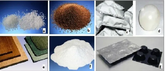
Many companies have exploited the potential of the PCMs according to the various forms that they can assume; for example some companies use the PCM in a powder form then encapsulated to realize PCM elements (bags, balls, capsules,....) or some companies integrate the PCM in their products (tanks, panels for partitions, ceiling, floor,....) in order to produce a PCM system. A good example of specific PCM products are the ice packs which are used to keep food cold.
Today more than 50 PCMs are commercially available and the number is growing from year to year. So, it is not possible to list all available commercial products because the companies produce several PCMs that are often similar one from each other. In the follows we reported some typical PCMs mostly used and known.
Fig. 8 Some typologies of commercial PCMs: compound material in powder form (a,b,f), bags (c), balls (d), panels (e), capsule strips (g).
37 For other detailed information we refer to the respective websites of the companies listed in the reference section at the end of this work.
Some of the most important and known companies which are engaged in the development and trade of PCMs are: Climator, Cristopia, EPS Ltd., Mitsubishi Chemical Corporation, Rubitherm, DuPont de Nemours and BASF. Some commercial PCMs available in the market are showed in the Tab. which includes their thermal and physical properties, as reported in the datasheets provided by the companies (melting point, heat of fusion and density), and the name of the company that produces them.
4.4. Application of PCMs in a building system.
Thanks to the properties previous exposed, the phase change materials can be used for several applications; in particular many surveys have demonstrated that they can be very suitable for building applications in order to reduce the energy consumption and improve the indoor thermal comfort for occupants due to the lowering of the temperature variations.
38 The use of PCMs in buildings provides different functions for different applications: they can be used for free cooling or heating of buildings, for shifting the building peak load, for using the solar energy, for recovering the waste heat, etc...
In general we can recognize two different ways to use the PCMs inside a building: - combination of PCMs with heating or cooling equipment (active system)
- integration of PCMs into the building envelope, such as walls, ceilings, floors,.... (passive system).
An active system means that the stored heat or cold is in a container thermally separated from the building and the charging and discharging process is achieved with the help of mechanical or electrical equipment.
The second system (passive) means that the stored heat or cold is automatically released when indoor or outdoor temperature rises or falls beyond the melting point; in this case the PCMs are integrated in the structure of buildings and the melting and freezing of PCMs is realized without using any mechanical equipment. Anyway, many factors affect the effectiveness of PCM system in a building: the type and amount of PCMs used, the PCM's encapsulation method, the location of PCMs in building structures, the building design and orientation, the equipment design and selection, the climate condition, the occupancy schedule, the system control and operational algorithms, etc...
Now we reported an overview of the most used solutions for PCM building application, but in the second part of this study we only considered the application according a passive method.
4.4.1. Active PCM systems.
The application of PCM according an active system has the goal of enhancing the heat transfer of a PCM storage. This system consists of a PCM storage unit integrated into other mechanical or electric systems, such as solar heat pump systems, heat recovery systems, floor heating systems, etc... in order to make a more complex solution that can increase the indoor thermal comfort with maximizing the performances of PCMs.
39 Many studies and experiments have been carried out on the various typologies of PCM application as active building systems, such as:
- electrical under-floor heating system with PCM storage that charges heat during the nighttime, when the electricity cost is cheaper, and discharges thermal energy during daytime (see Farid and Chen, Lin);
- a roof integrated with solar heating system with PCM storage which utilizes the existing roof as a solar collector/absorber incorporating PCMs (see Bruno); - combined solar heat pump with energy storage (see Kaygusuz and Ayan); - a solar space heating system incorporating PCMs that consistis of an array of solar flat plate collectors which deliver heated water to a storage tank, and a number of PCM filled panels melting the PCM (see Kenneth);
- phase change material combined with a night ventilation system, such as an array of PCM bags applied in the ceiling (see Kang) or PCMs embedded in a wall surface in combination with a night ventilation plant (see Zhong);
- a heat recovery system using PCMs, which recovers rejected heat of air conditioning systems in order to produce low temperature hot water for washing and bathing (see Gu).
4.4.2. Passive PCM systems.
A passive system consists of the integration of PCMs into the components of the building envelope (i.e. walls, roofs and floors) as part of building materials or structures to increase the building thermal mass. This system works according this procedure: during the daytime the PCM absorbs melting heat from indoor air until it reaches its melting point in temperature; during the night the PCM releases the stored heat at the indoor space through the building structure until it decreases to the solidification temperature. A passive system could be very effective on indoor thermal comfort because it reduces the indoor overheating during the daytime in
hot summer, provides heat for space heating during night in cold winter,increases
the thermal capacity of the light building envelopes and also reduces the room temperature fluctuation. This implies none or less demands of energy and a lower energy consumption.
40 As we just said, a PCM passive system can be made by embedding PCMs into the building materials (such as bricks, concrete, plaster,...) or by integrating them into the building components (such as walls, ceilings, floors, windows,...).
Some examples of PCM applications as passive building systems are the following: - trombe wall integrated with PCM, which consists of a wall filled with PCMs standing on the south side of a house and facing a double-layer of glass. The incoming solar radiation is collected in the space between the wall and the glazing and it produces the melting of PCMs; at night the heat is released to the indoor environment in order to warm the house.
- wallboards incorporating PCMs which consist of the encapsulation of PCMs (the effectiveness depends on the PCM's quantity) into a thin panel which allows an easy installation in any typology of building, particularly in the case of building retrofit. This system can also be installed on the floor or ceiling .
- PCM incorporated into building materials (bricks, concrete, gypsum,...). This
method represents a suitable way to use PCMs thanks to lower costs, easier fabrication and widespread application. This solution achieves interesting results but the better performance can be obtained by incorporating PCMs into porous materials, such as plasterboard or gypsum.
These are some of the several applications of PCMs as active or passive storage systems; many other solutions have already been studied and experimented, but many surveys about the various possible PCM-technologies are in progress.
In the second part of the present work we only considered the application of a passive energy storage system consisting of the application of the PCM panels in the interior partitions of a room.
Fig. 9 Scheme of a system incorporated PCM: roof integrated with solar heating devices (left) and electrical under floor heating system (right).
41
PART II
5. The simulation tools.
In order to achieve the purposes of the present study, we used the building simulation software EnergyPlus. This program is developed by the United States Department of Energy and allows the building energy analysis and its thermal load simulation (heating and cooling loads) taking into account the building's physical description (location, materials, construction, etc... ) and its mechanical systems. This software is based on the previous programs BLAST (Building Loads Analysis and System Thermodynamics) and DOE-2 (Department Of Energy), which were two of the most important simulation programs developed in the 1970's in order to carry out a load and energy simulation of a building. The main difference between these two programs is the load calculation method: DOE-2 uses a room weighting factor approach while BLAST uses a heat balance approach.
Each program comprises hundreds of subroutines working together to simulate heat and mass flows throughout a building. In some cases, subroutines in DOE-2 were more accurate. In other cases, subroutines in BLAST were more accurate. In 1996 the Department of Energy of United States developed a new simulation tool named EnergyPlus, which is based on the merging of the two above mentioned programs. So, EnergyPlus results from the combination of many features of BLAST and DOE-2 but with more and new capabilities.
5.1. Structure of EnergyPlus
EnergyPlus is a simulation program based on a modularity system; it runs according sub-hourly calculations and considers, at the same time, the load and system dynamic performance into the whole building energy balance.
The program consists of three modules: a simulation manager that incorporates the heat and mass balance simulation module and the building system simulation modules (the scheme of the program is shown in Fig. 10).
The first component (simulation manager) controls the entire simulation process, such as the interactions between all simulation loops (environment, day, hour and
42 sub-hour) and simulation period (whether day, month, season, year or several years). Actions among individual simulation modules are directed by the simulation manager, instructing simulation modules to take actions such as initialize, simulate, record keep, or report.
The second module, heat and mass balance simulation, consists of two modules: a
surface heat balance module and an air heat balance module. The surface heat balance module simulates inside and outside surface heat balance, interactions between heat balances and boundary conditions, conduction, convection, radiation, and mass transfer (water vapor) effects. The air heat balance module acts as an interface between the surface heat balance and the building systems simulation; it takes into account the thermal mass of zone air and evaluates the direct convective heat gains in the building loads simulation.
This modelconsiders these assumptions:
- the air mass balance is calculated considering all mass streams (ventilation air, exhaust air and infiltration);
- the air in each thermal zone is considered as well mixed element with uniform temperature throughout;
- room surfaces (walls, windows, ceilings and floors) have uniform surface temperatures, uniform long and short wave irradiation, diffuse radiating surfaces and internal heat conduction.
43 The building systems simulation module controls the communication between the heat balance engine and various HVAC modules and loops, such as coils, boilers, chillers, pumps, fans and other equipment/components.
5.2. EnergyPlus calculation methodologies.
The heat balance on the zone air is expressed by the "Zone Air Heat Balance Algorithm" object; it allows to choose the type of solution algorithm that will be used to calculate zone air temperatures and humidity ratios.
The basic equation for the zone air and heat balance is the following:
sys z p N i N i i p zi z z si i i N i i z z
dt
Q
h
A
T
T
m
C
T
T
m
C
T
T
Q
dT
C
surfaces zones sl
(
)
(
)
inf(
)
1 1 1 (7) where:
sl N i iQ
1
= sum of the convective internal loads.
surfaces N i z si i iA T T h 1 )( = convective heat transfer from the zone surfaces.
minfCp(T Tz)= heat transfer due to infiltration of outside air.
zones N i z zi p iC T T m 1 ) ( = heat transfer due to interzone air mixing.
Q
sys
m
sysC
p(
T
sup
T
z)
= air system output.
dt
dT
C
zz = energy stored in the zone air.
The filling of the "Zone Air Heat Balance Algorithm" as EnergyPlus input is optional. To the purpose of this work, we have to take special care of the thermal behavior of the construction materials when they are subjected to a heat flow transfer; so, first we considered very important to understand how EnergyPlus works during
44 the "surface heat balance" processes in order to use the most suitable heat transfer algorithm according test conditions. To this aim we used the "Heat Balance Algorithm" to carry out the simulations.
The "Heat Balance Algorithm" object represents the heat and moisture transfer algorithm that is used across the building construction calculations.
The types of calculation are the following: - Conduction transfer function (CTF);
- Effective Moisture Penetration Depth with Conduction Transfer Function (EMPD); - Conduction Finite Difference (CFD);
- Conduction Finite Difference Simplified (CFDS); - Combined Heat And Moisture Finite Element (HAMT).
In this work we have utilized two kinds of heat transfer equation: the Conduction Transfer Function (CTF) and the Conduction Finite Difference (CFD).
5.2.1. Conduction Transfer Function.
The first method represents a traditional way of simulating the heat transfer, such as the time series coefficients that describe the transient conduction process with an algebraic equation.
The equations that represent the conduction heat transfer are the following: - for the inside flux
(8)
- for the outside flux
" , 1 , 1 , , 1 , " kot j nq j j j t o nz j j t o o j t i nz j j t i o ko t YT Y T X T X T q q
(9) where:q"ko = Conduction heat flux on outside face
q"ki = Conduction heat flux on inside face
Xj = Outside CTF coefficient, j= 0,1,...nz. Yj = Cross CTF coefficient, j= 0,1,...nz.