UNIVERSITÀ DEGLI STUDI DI CATANIA
FACOLTÀ DI INGEGNERIA
Dipartimento di Ingegneria Elettrica, Elettronica e Informatica
Cristina Ventura
Theoretical and Experimental
Development of a Photovoltaic Power
System for Mobile Robot Applications
Ph.D. Thesis
Electrical Engineering
XXIV Cycle
Supervisor:
Ch.mo Prof. Ing. Tina Giuseppe Marco
i
Index
Abstract iv Acknowledgement vii Nomenclature viii Preface xCHAPTER I Photovoltaic Systems 1
1.1. Theory ... 3
1.2. p-n junction ... 4
1.3. PV cells characteristic ... 5
1.4. Grid connected and Stand-Alone ... 11
1.5. Types of PV technology ... 13
1.6. Batteries ... 15
CHAPTER II Design considerations about a Photovoltaic Power System to Supply a Mobile Robot 17 2.1. State of the art ... 19
2.2. The hybrid robot TriBot design ... 20
2.2.1. Mechanical design ... 24
2.2.2. Electrical characteristics ... 25
2.2.3. Robot Consumption ... 29
2.3. Placement of PV panels analysis ... 33
2.4. PV system sizing problem ... 36
CHAPTER III A novel MPPT charge regulator for a photovoltaic mobile robot application 40 3.1. Statement of problem ... 40
ii
3.2.1. Fractional Open-Circuit Voltage Method ... 44
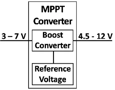
3.3. MPPT charge regulator ... 45
3.3.1. Fixed reference voltage ... 46
3.3.2. Fixed reference voltage with temperature compensation ... 47
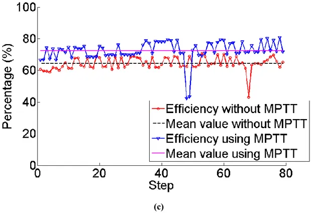
3.4. Experimental Results ... 48
CHAPTER IV Sub-hourly irradiance models on the plane of array for photovoltaic energy forecasting applications 55 4.1. Analysis of forecast errors for irradiance on the horizontal plane ... 58
4.1.1. Evaluation of the Solar Irradiation Forecasts Errors ... 58
4.1.2. Classification of daily solar radiation ... 59
4.1.3. Neural Network ... 61
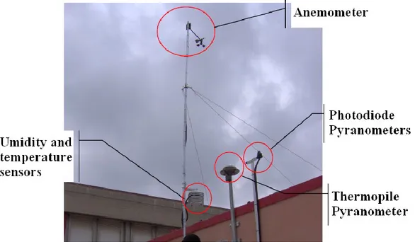
4.1.4. Experimental Setup ... 65
4.1.5. Experimental Results ... 69
4.2. Clear Sky Radiation Model on Horizontal Surface ... 74
4.2.1. Clear sky direct-beam radiation ... 74
4.2.2. Clear sky diffuse radiation ... 76
4.3. Sub-hourly irradiance models on the plane of array ... 77
4.3.1. Beam and diffuse components of hourly radiation ... 77
4.3.2. Solar Radiation on Inclined Surface ... 79
4.4. Deriving the temperature profile from the irradiance profile ... 94
CHAPTER VModel of a stand-alone photovoltaic system 97 5.1. I-V characteristic generation ... 99
5.1.1. The reference parameters ... 99
5.1.2. Dependence of the parameters on operating conditions ... 102
5.1.3. PV cells temperature and irradiance ... 104
5.2. Load ... 106
5.3. Results ... 106
iii
APPENDIX A Environmental Characteristics 116
6.1. Incident radiation and its components ... 116 6.2. Solar trajectory ... 117 6.3. Solar Energy ... 131
iv
Abstract
The development of mobile robotics structures has recently become an area of great interest to researchers and industry. These robotics platforms should be, as much as possible, autonomous and self-sufficient, also from the energetic point of view. In this context, energy scavengers using small photovoltaic modules have been recently proposed to increase the autonomy and perform continued operation of embedded systems.On the basis of this fervent research activity, the primary goal of this work is the theoretical and experimental development of micro and mini systems for the photovoltaic production and the energy storage.
Nowadays, the vision of developing perpetual power devices without periodical human intervention is one of the challenges of embedded systems design. This can be done harvesting energy efficiently from the environment. In order to account for all the objectives: lifetime, flexibility, simplicity, cost, up to now, the best compromise appears to be the use of micro solar power system with rechargeable batteries. The use of this strategy for supplying systems with limited size and mass, but nevertheless high power requirements, such as a mobile robot, has been first studied. The system taken as test-bed in the experiment is a bio-inspired mobile robot, called TriBot.
First of all, a preliminary analysis of the feasibility of a photovoltaic system with batteries to supply this mobile robot has been done. Considering the different solutions that can be used to place the PV cells on the robot structure, the different photovoltaic technologies present on the market with their efficiencies and costs and the power consumption of the robot, the conclusion is that, using the photovoltaic system here proposed, it is possible to increase the autonomy of the robot.
Since in the PV system here analyzed the amount of area that can be used to place the PV cells is very limited and therefore few solar cells can be employed, a very efficient charging system is an essential requisite. To this aim, a novel photovoltaic charge regulator for mobile applications, which uses the Fractional Open-Circuit Voltage MPPT method, is proposed. The purpose of the implemented MPPT algorithm is to optimize the efficiency of the harvesting process, minimizing the complexity and therefore the power consumption.
v A typical stand-alone photovoltaic system includes a solar array, batteries, regulator and load. In order to model the whole system and to evaluate its performance, a Simulink model in Matlab environment has been developed. Meteorological conditions (radiance, temperature) are essential to estimate the power production of the photovoltaic system. In the simulator, measured values of the radiation and the temperature have been used. Anyhow, it will be possible to use predicted values considering the forecast solar radiation and to calculate the temperature from the solar radiation profile.
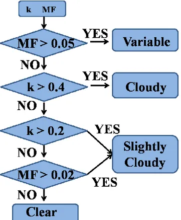
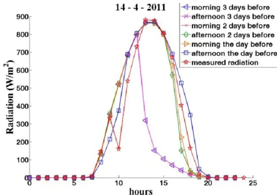
In this work, data given us by a weather forecast provider have been used. First of all these predicted data have been compared with the measured ones, in order to determine their accuracy, using the normalized Root Mean Square Error (nRMSE) as mean measure. Then, a method to classify each minute of a day as variable, cloudy, slightly cloudy or clear has been implemented. In this way it is possible to understand if there is a correlation between the percentages of the minutes of a specific day that belong to each class and the error done on that day. Using a neural network, a correlation between these percentages and the error done in that day has been found.
The knowledge of solar radiation forecasts and therefore the availability of energy for the batteries and the load is a crucial part for these kinds of autonomous systems whose energetic consumption is very changeable. The knowledge of the available energy, in fact, should allow to implement power saving strategies optimizing the activities of the robot.
The weather provider gives us information about the solar radiation on the horizontal plane. Moreover, the global irradiance on a horizontal surface has been measured in many meteorological stations around the world, but there are only a few stations that measure this solar component on inclined surfaces. However, the PV panel exposition is not assumed to be a control variable due to the fact that the robot can change its posture operating on uneven terrains. To collect the maximum solar radiation the PV cells have to be oriented toward south, this is not the case for a moving robots that has to follow the optimal path to carry out its task. For these reasons, models are required to estimate the solar radiation on the plane of the PV array starting from the radiation on the horizontal plane. To this aim, in literature there are a number of models available, but these models require information at the same time on the global and the direct or diffuse irradiance on a horizontal surface. Consequently, the variation of the diffuse component with global irradiation has been firstly studied, then the different methods to calculate the hourly irradiation on the plane of the PV array present in literature have been analyzed and those which show the best results have been implemented;
vi in particular Perez and Klucher models have been developed. Moreover, a neural network that allows to evaluate the global solar radiation on the tilted surface directly from the global solar radiation measured on the horizontal plane, without the need to slit it into the direct and diffuse components, has been developed.
Once that the solar radiation, measured or forecast, incident on the solar cells used to recharge the batteries of the robot, at any inclination and orientation the robot will assume; the power consumption of the robot and the efficiency of the charge regulator are known, all these information can be used in the Simulink model that, therefore, can become a very helpful tool to estimate the power production of the photovoltaic system and therefore the increase of the autonomy of the embedded systems used as load.
vii
Acknowledgement
I would first like to thank my supervisor, Professor Ing. Giuseppe Tina, for his continuous guidance throughout the period of my PhD studies, whose interest, expertise, and guidance was essential in directing and completing this project.I would like to express my gratitude to Professor Ing. Paolo Arena, for his support and constant guide.
For their sympathy and support during these years, many thanks to my colleagues for their help and support.
I want to remember the inestimable contribution of my family that has always believed in me, sustaining and encouraging me in all the phases of my personal and professional life.
Finally, an enormous thank to all my friends who offered continual support and needed distractions.
viii
Nomenclature
Symbol Description
Solar altitude angle
Short circuit current temperature coefficient
β Surface tilt angle
Open circuit voltage temperature coefficient
γ Surface azimuth angle
Declination Sky's clearness Specific Resistance θ Angle of incidence Angle of refraction Ideality factor Albedo coefficient ω Hour angle Sky's brightness FF Fill factor
Beam radiation on the tilted plane Beam radiation on the horizontal plane Diffuse radiation on the tilted plane Diffuse radiation on the horizontal plane Extraterrestrial horizontal radiation Ground-Reflected radiation on the tilted plane Global radiation on the tilted plane
IMPP Maximum current
ix
IPH Photo-generated current
ISC Short-circuit current
K Boltzmann‘s gas constant
kt Clearness index
MA Moving Average
MF Moving Function
MSE Mean Square Error
q Electronic charge
RMSE Root Mean Square Error
VMPP Maximum voltage
VOC Open-circuit voltage
x
Preface
In the twenty-first century an emerging theme for the need of more environmentally benign electric power systems is a critical part of this new thrust. Renewable energy systems that take advantage of energy sources that won‘t diminish over time and are independent of fluctuations in price and availability are playing an ever-increasing role in modern power systems.Over the past century, fossil fuels provided most of our energy, because these were much cheaper and more convenient than energy from alternative energy sources, and until recently, environmental pollution has been of little concern. The main problem is that proven reserves of oil and gas, at current rates of consumption, would be adequate to meet demand for only another 41 and 67 years, respectively. The reserves for coal are in a better situation; they would be adequate for at least the next 230 years. If we try to see the implications of these limited reserves, we are faced with a situation in which the price of fuels will accelerate as the reserves decreases. Since the global acknowledgment of the population upon the pollution generated by coal and oil, the focus is on the renewable energies. Many alternative energy sources can be used instead of fossil fuels. The decision as to what type of energy source should be utilized in each case must be made on the basis of economic, environmental, and safety considerations.
Because of the desirable environmental and safety aspects, it is widely believed that solar energy should be utilized instead of other alternative energy forms because it can be provided sustainably without harming the environment. The greatest advantage of solar energy as compared with other forms of energy is that it is clean and can be supplied without environmental pollution. Therefore, solar energy technologies can play an important role in meeting the ultimate goal of replacing fossil fuels to generate inexhaustible, clean and safe energy.
Up to now, the off-grid PV power generation system is widely used in the portable applications to provide clear and long energy with a high power density. Nowadays, in fact, solar energy harvesting has become increasingly important as a way to improve lifetime and reduce maintenance cost of portable appliances and stand alone power systems. Among energy harvesting methods, in fact, photovoltaic (PV) sources have the highest energy
xi density, they guarantee supply security and sustainable environment; consequently, they represent, at present, the best way to gather energy from the environment.
In this context, this thesis will focus on the theoretical and experimental development of micro and mini systems for the photovoltaic production and the energy storage.
In the document, first of all the main characteristics of photovoltaic systems are introduced, in order to understand how the PV cells convert energy of the solar radiation into electrical energy.
During the last years, a considerable attention was devoted to the study and development of robotics structures that can deal with difficult environments to solve complex tasks, such as outdoor cluttered environment exploration, pipe inspection, mine clearance and others. These robotic systems can be classified according to their structure, dimensions, maneuverability, main tasks, and so on. One of the major obstacles in the use of autonomous robots in remote environments has to do with power supply. Every robot, in fact, requires a power source to perform all its functions, like navigation, measurements, and manipulations, to name just the most important. To be autonomous, a robot should perform its duties while maintaining enough energy to operate. Nowadays, in fact, the vision of developing perpetual power devices without periodical human intervention is one of the challenges of embedded systems design. This can be done harvesting energy efficiently from the environment. In this context, in Chapter II, the use of photovoltaic for supplying systems with limited size and mass, but on the other hand high power requirements, such as a mobile robot, has been studied. The system taken as test-bed in the experiment is a bio-inspired mobile robot, called TriBot. Long-term operation is an important goal of many mobile electronic systems. One may attempt to achieve this goal in three ways: reduce energy consumption of the system, increase energy capacity of the battery and replenish battery energy over time. Energy reduction can be done by improving hardware design and more intelligent power management. Therefore, in order to built an efficient autonomous power supply system, studies about power consumptions of the robot have been done. Moreover, some possible structures that will be placed on the robot to incorporate the PV cells have been analyzed and using AutoCAD, some examples of covering structures for the robot have been also analyzed.
Unfortunately using photovoltaic systems there are two significant shortcomings: first of all the conversion efficiency of electric power generation is very low, especially under low irradiance conditions, moreover the solar panels generate an amount of electric power that changes continuously with weather conditions. Considering all these problems, the
xii optimization of the energy harvesting process under varying light irradiance conditions is certainly one of the major design challenges for PV systems. Harvested power can be maximized if the cells and the load are impedance matched in every light irradiance and temperature conditions. To this aim, in most PV systems a particular technique, namely Maximum Power Point Tracking (MPPT), is adopted. Therefore, in Chapter III the MPPT techniques available in literature and a novel MPPT charge regulator for photovoltaic mobile robot applications are presented.
The stand-alone system presented in this thesis is composed by different parts: PV cells, batteries, the MPPT charge regulator and load. In order to evaluate the performance of the whole system, a Simulink model in Matlab environment has been developed. To estimate the power production of the photovoltaic system, it is needed to know meteorological conditions: radiance, temperature; these data can be measured or forecast. In the case of forecast values, in this work, data given us by a weather forecast provider have been used. In Chapter IV, the accuracy of these predicted data has been evaluated, comparing these with the measured ones. Then, the method implemented to classify each minute of a day as variable, cloudy, slightly cloudy or clear has been presented. In this way, it is possible to understand if there is a correlation between the percentages of the minutes of a specific day that belong to each class and the error done on that day. The neural network, which allows to find a correlation between these percentages and the error done in that day, has been described. Forecast solar radiation allows to know in advance the available energy for the batteries and the load, therefore power saving strategies for the robot can be implemented. Practically, forecasting the solar radiation of the day after it is possible to control the actions of the robot basing on the kind of day; for example, if tomorrow will be clear day, the robot could perform all its duties without problems, while if tomorrow will be a cloudy day, the robot can preserve its energy just transmitting data and maintaining a continuous communication of the robot with other robots and with a base station.
Measured and forecast solar radiations are relative to the horizontal plane. Anyhow, an autonomous robot can move around the environment and therefore its inclination and orientation will not always be the same. Accordingly, models are required to estimate the irradiance on the tilted surface of the PV system from radiation on horizontal ones; these models are also analyzed.
xiii Finally, the model of the PV system developed in Simulink is presented in Chapter V. This simulator represents a powerful tool to estimate the power production of the photovoltaic system and therefore the increase of the autonomy of the embedded systems used as load.
All the algorithms and methods have been developed using Matlab environment and Labview. Matlab has been chosen for the following reasons: it provides many built in auxiliary functions useful for function optimization, it is completely portable and it is efficient for numerical computations. While Labview, which was used to acquire measurements from the external environment, has been chosen because it allows to quickly and easily acquire real-world signals, to perform analysis to ascertain meaningful data and to communicate or store results in a variety of ways.
1
CHAPTER I
Photovoltaic Systems
With the increase of the energy demand and the concern of environmental pollution around the world, photovoltaic power systems are becoming more and more popular.The sun is regarded as a good source of energy for its consistency and cleanliness, unlike other kinds of energy such as coal, oil, and derivations of oil that pollute the atmosphere and the environment. The sun is the only star of our solar system located at its center. The earth and other planets orbit the sun. Energy from the sun in the form of solar radiation supports almost all life on earth via photosynthesis and drives the earth‘s climate and weather. Sunlight is the main source of energy to the surface of the earth that can be harnessed via a variety of natural and synthetic processes [1]. Basically all the forms of energy in the world are solar in origin. Oil, coal, natural gas, and wood were originally produced by photosynthetic processes, followed by complex chemical reactions in which decaying vegetation was subjected to very high temperatures and pressures over a long period of time. Even the energy of the wind and tide has a solar origin, since they are caused by differences in temperature in various regions of the earth.
Most scientists, because of the abundance of sunshine capable of satisfying our energy needs in the years ahead, emphasize the importance of solar energy [2]. Solar energy is obviously environmentally advantageous relative to any other renewable energy source, and the linchpin of any serious sustainable development program. It does not deplete natural resources, does not cause CO2or other gaseous emission into air or generates liquid or solid
waste products.
Solar energy is one of the most promising renewable resources that can be used to produce electric energy through photovoltaic process. A significant advantage of photovoltaic systems is the use of the abundant and free energy from the sun. Concerning sustainable development, the main direct or indirectly derived advantages of solar energy are the following: no emissions of greenhouse (mainly CO2, NOx) or toxic gasses (SO2, particulates),
reclamation of degraded land, reduction of transmission lines from electricity grids, increase of regional/national energy independence, diversification and security of energy supply,
2 acceleration of rural electrification in developing countries [3]. Moreover, solar energy is a vital that can make environment friendly energy more flexible, cost effective and commercially widespread.
Photovoltaic source are widely used today in many applications such as battery charging, water heating system, satellite power system, and others [4]. Moreover, the off-grid PV power generation system is widely used in the portable applications to provide clear and long energy with a high power density.
Photovoltaic modules are solid-state devices that convert sunlight, the most abundant energy source on the planet, directly into electricity without an intervening heat engine or rotating equipment [1]. PV equipment has no moving parts and, as a result, requires minimal maintenance and has a long life. It generates electricity without producing emissions of greenhouse or any other gases and its operation is virtually silent. PV systems can be built in virtually any size, ranging be easily added to increase output. PV systems are highly reliable and in produce a PV panel was more than the energy the panel could produce during its lifetime. During the last decade, however, due to improvements in the efficiency of the panels and manufacturing methods, the payback times were reduced to 3–5 years, depending on the sunshine available at the installation site.
Solar energy is the oldest energy source ever used. The sun was adored by many ancient civilizations as a powerful god. The first known practical application was in drying for preserving food [2]. The history of photovoltaics (PVs) began in 1839 when a 19-year-old French physicist [5], Edmund Becquerel, was able to cause a voltage to appear when he illuminated a metal electrode in a weak electrolyte solution (Becquerel, 1839). Almost 40 years later, Adams and Day were the first to study the photovoltaic effect in solids (Adams and Day, 1876). They were able to build cells made of selenium that were 1% to 2% efficient. Selenium cells were quickly adopted by the emerging photography industry for photometric light meters; in fact, they are still used for that purpose today. In 1905, Albert Einstein published four papers in the Annalen der Physik journal; The first one was his explanation of the photoelectric effect. About the same time, in what would turn out to be a cornerstone of modern electronics in general, and photovoltaics in particular, a Polish scientist by the name of Czochralski began to develop a method to grow perfect crystals of silicon. By the 1940s and 1950s, the Czochralski process began to be used to make the first generation of single-crystal silicon photovoltaics, and that technique continues to dominate the photovoltaic industry today.
3 In the 1950s there were several attempts to commercialize PVs, but their cost was prohibitive. The first practical application of solar cells was in space, where cost was not a barrier, since no other source of power is available [1]. Research in the 1960s resulted in the discovery of other photovoltaic materials such as gallium arsenide (GaAs). These could operate at higher temperatures than silicon but were much more expensive.
Despite their high cost, PV systems are cost effective in many areas that are remote from utility grids, especially where the supply of power from conventional sources is impractical or costly. For grid connected distributed systems, the actual value of photovoltaic electricity can be high because this electricity is produced during periods of peak demand, thereby reducing the need for costly extra conventional capacity to cover the peak demand. Additionally, PV electricity is close to the sites where it is consumed, thereby reducing transmission and distribution losses and thus increasing system reliability.
1.1. Theory
A PV cell consists of two or more thin layers of semiconducting material, most commonly silicon. When the silicon is exposed to light, electrical charges are generated; and this can be conducted away by metal contacts as direct current. The electrical output from a single cell is small, so multiple cells are connected and encapsulated (usually glass covered) to form a module (also called a panel). The PV panel is the main building block of a PV system, and any number of panels can be connected together to give the desired electrical output. This modular structure is a considerable advantage of the PV system, where further panels can be added to an existing system as required [1].
Therefore, a material or device that is capable of converting the energy contained in photons of light into an electrical voltage and current is said to be photovoltaic. A photon with short enough wavelength and high enough energy can cause an electron in a photovoltaic material to break free of the atom that holds it. If a nearby electric field is provided, those electrons can be swept toward a metallic contact where they can emerge as an electric current. The driving force to power photovoltaics comes from the sun, and it is interesting to note that the surface of the earth receives something like 6000 times as much solar energy as our total energy demand [5].
Photovoltaics use semiconductor materials to convert sunlight into electricity. The technology for doing so is very closely related to the solid-state technologies used to make
4 transistors, diodes, and all of the other semiconductor devices that we use so many of these days [5]. Solar cells are made of semiconductor materials, which are specially treated to form an electric field, positive on one side (backside) and negative on the other (towards the sun). The standard silicon (Si) solar cell is based on a semiconductor p-n junction. The contact of n-doped and p-n-doped layers forms a p-n junction, where doping is a process of introducing impurities into a pure semiconductor.
1.2. p-n junction
At present, the most frequent example of solar cell structure is realized with crystalline silicon (c-Si). A moderately-doped p-type c-Si with an acceptor concentration of 1016cm3is used as the absorber. On the top side of the absorber a thin, less than 1 μm thick, highly-doped
n-type layer is formed as the electron membrane. On the back side of the absorber a
highly-doped p-type serves as the hole membrane. At the interfaces between the c-Si p-type absorber and the highly-doped n-type and p-type membranes, regions are formed with an internal electric field [6]. These regions are especially important for solar cells and are known as p-n junctions. The presence of the internal electric field in the solar cell facilitates the separation of the photo generated electron-hole pairs. When the charge carriers are not separated from each other in a relatively short time they will be annihilated in a process that is called recombination and thus will not contribute to the energy conversion. The easiest way to separate charge carriers is to place them in an electric field. In the electric field the carriers having opposite charge are drifted from each other in opposite directions and can reach the electrodes of the solar cell. The electrodes are the metal contacts that are attached to the membranes.
The p-n junction fabricated in the same semiconductor material such as c-Si is an example of the p-n homo-junction. There are also other types of a junction that result in the formation of the internal electric field in the junction. The p-n junction that is formed by two chemically different semiconductors is called the p-n hetero-junction. In the p-i-n junctions, the region of the internal electric field is extended by inserting an intrinsic, i, layer between the p-type and the n-type layers. The i-layer behaves like a capacitor and it stretches the electric field formed by the p-n junction across itself. Another type of the junction is a junction between a metal and a semiconductor, MS junction. The Schottky barrier formed at the metal-semiconductor interface is a typical example of the MS junction.
5 When a p-n junction is illuminated the additional electron-hole pairs are generated in the semiconductor. The concentration of minority carriers (electrons in the p-type region and holes in the n-type region) strongly increases. This increase in the concentration of minority carriers leads to the flow of the minority carriers across the depletion region into the quasi neutral regions. Electrons flow from the p-type into the type region and holes from the n-type into the p-n-type region. The flow of the photo-generated carriers causes the so-called photo-generation current, IPH.
1.3. PV cells characteristic
A photovoltaic PV generator is mainly an assembly of solar cells, connections, protective parts, and supports. As was seen already, solar cells are made of semiconductor materials, usually silicon, and are specially treated to form an electric field with positive on one side (backside) and negative on the other side, facing the sun.
When solar energy (photons) hits the solar cell, electrons are knocked loose from the atoms in the semiconductor material, creating electron-hole pairs. If electrical conductors are then attached to the positive and negative sides, forming an electrical circuit, the electrons are captured in the form of electric current IPH [3]. From this description, it is obvious to deduce that during darkness the solar cell is not active and works as a diode, i.e., a p-n junction that does not produce any current or voltage. If, however, it is connected to an external, large voltage supply, it generates a current, called the diode or dark current, ID.
Thus the simplest equivalent circuit of a solar cell is a current source in parallel with a diode, shown in Figure 1.1. The output of the current source is directly proportional to the light falling on the cell (photocurrent IPH). A plot of output current against the output voltage of the solar cell is called the I −V curve when it is under illumination. The I-V characteristic of the cell is determined by the diode [7].
6
Figure 1.1: Circuit diagram of the PV model.
As shown in Figure 1.1, the model contains a current source, IPH, one diode, and a series resistance RS, which represents the resistance inside each cell. The diode has also an internal shunt resistance, RSH. The net current is the difference between the photocurrent, IPH, and the normal diode current, ID, given by [1]:
(1.1)
It should be noted that the shunt resistance is usually much bigger than a load resistance, whereas the series resistance is much smaller than a load resistance, so that less power is dissipated internally within the cell. Therefore, by ignoring these two resistances, the net current is the difference between the photocurrent, IPH, and the normal diode current, ID, given by:
(1.2)
where:
Vt is the thermal voltage (V) ,
;
k is Boltzmann‘s gas constant, k = 1.381 x 10⁻²³ J/K;
TC is absolute temperature of the cell (K); q is electronic charge, q = 1.602 x 10⁻¹⁹ J/V;
V is voltage imposed across the cell (V);
7 Figure 1.2 shows the I-V characteristic curve of a solar sell for certain irradiance, GT at a fixed cell temperature, TC.
Figure 1.2: Representative current-voltage curve for photovoltaic cells.
The current from a PV cell depends on the external voltage applied and the amount of sunlight on the cell. When the cell is short-circuited, the current is at maximum (short-circuit current, ISC), and the voltage across the cell is 0. When the PV cell circuit is open, with the leads not making a circuit, the voltage is at its maximum (open-circuit voltage, VOC), and the current is 0. In either case, at open circuit or short circuit, the power (current times voltage) is 0. Between open circuit and short circuit, the power output is greater than 0. The typical current-voltage curve shown in Figure 1.2 presents the range of combinations of current and voltage. The power can be calculated by the product of the current and voltage.
8
Figure 1.3: Representative power-voltage curve for photovoltaic cells.
The maximum power passes from a maximum power point, at which point the load resistance is optimum and the power dissipated in the resistive load is maximum and given by:
(1.3)
The operating point PMPP, IMPP, VMPP at which the output power is maximized is also calledthe maximum power point.
Therefore, a real solar cell can be characterized by the following fundamental parameters [7]: Short circuit current: ISH =IPH. It is the greatest value of the current generated by a cell. It
is produce by the short circuit conditions: V = 0. The short-circuit current of a solar cell depends on the photon flux density incident on the solar cell, that is determined by the spectrum of the incident light, and on the area of the solar cell;
Open circuit voltage, VOC. It correspond to the voltage drop across the diode (p-n junction), when it is transverse by the photocurrent IPH, namely when the generated currents is I = 0. The VOC corresponds to the forward bias voltage, at which the dark current
compensates the photo-current. It depends on the photo-generated current density. It reflects the
voltage of the cell in the night and it can be mathematically expressed as:
(1.4)
Maximum power point. It is the operating point (IMPP, VMPP);9 The conversion efficiency, . It is calculated as the ratio between the generated maximum power and the incident power. The irradiance value, Pin, of 1000 W/m2 of AM1.5
spectrum has become a standard for measuring the conversion efficiency of solar cells.
(1.5)
Typical external parameters of a crystalline silicon solar cell are: ISC of 35 mA/cm2, VOC
up to 0.65 V and FF in the range 0.75 to 0.80. The conversion efficiency lies in the range of 17 to 18%.
Fill factor, FF, is the ratio of the maximum power that can be delivered to the load and he product of ISC and VOC. Given Pmax, it can be calculated such that:
(1.6)
(1.7)
The fill factor is a measure of the real I-V characteristic. Its valued is higher than 0.7 for good cells. The fill factor diminishes as the cell temperature is increased.
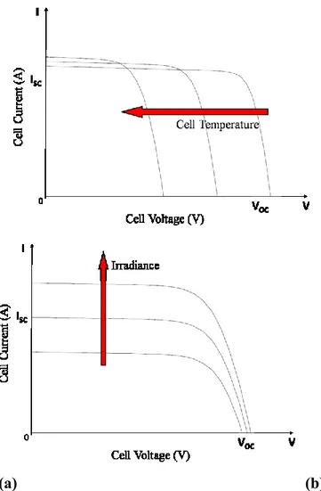
The open circuit voltage increases logarithmically with the ambient irradiation, while the short circuit current is a linear function of the ambient irradiation. The dominant effect with increasing cell‘s temperature is the linear decrease of the open circuit voltage, the cell being thus less efficient. The short circuit current slightly increases with the cell temperature [7].
The I-V characteristic of the solar cell, presented in Figure 1.2, is only for a certain irradiance, GT, and cell temperature, TC. The influences of these two parameters on the cell
characteristics are shown in Figure 1.4.a and 1.4.b. As shown in Figure 1.4.a, the open circuit voltage increases logarithmically by increasing the solar radiation, whereas the short-circuit current increases linearly. The influence of the cell temperature on the cell characteristics is shown in Figure 1.4.b. The main effect of the increase in cell temperature is on open circuit voltage, which decreases linearly with the cell temperature; thus the cell efficiency drops. As it is possible to note, the short-circuit current increases slightly with the increase of the cell temperature [1].
10
(a) (b)
Figure 1.4: Influence of irradiation and cell temperature on PV cell characteristics. (a)
Effect of increased irradiation. (b) Effect of increased cell temperature.
In practice solar cells can be connected in series or parallel. Figure 1.5 shows how the I-V curve is modified in the case where two identical cells are connected in parallel and in series. As can be seen, when two identical cells are connected in parallel, the voltage remains the same but the current is doubled; when the cells are connected in series, the current remains the same but the voltage is doubled [1].
11
(a) (b)
Figure 1.5: Parallel and series connection of two identical solar cells. (a) Parallel
connection. (b) Series connection.
1.4. Grid connected and Stand-Alone
Photovoltaic applications can be divided into two broad areas [8]: Grid Connected systems.
- A grid-connected energy system is an independent decentralized power system that is connected to an electricity transmission and distribution system (referred to as the electricity grid). They are ideal for locations close to grid;
- The operational capacity is determined by the supply source. The system functions only when the supply sources are available;
- Because of the supply driven operation, the system may have to ignore the local demand during times of unavailability of supply sources;
- The system could be either used to meet the local demand and surplus can be fed to the grid, or otherwise, the system may exist only to feed the grid;
- The connectivity to grid enables setting up relatively large-scale systems and hence they can operate at high plant load factors improving the economic viability of the operation;
- In a grid-connected power system the grid acts like a battery with an unlimited storage capacity. So it takes care of seasonal load variations.
12 As a result of which the overall efficiency of a grid-connected system will be better than the efficiency of a stand-alone system, as there is virtually no limit to the storage capacity, the generated electricity can always be stored, and the additional generated electricity need not be ‗‗thrown away‘‘;
- In addition to the initial cost of the system, cost for interface of the system with grid is incurred;
- For systems operating on renewable sources like biomass, wind and solar PV, there will be a high pressure on these renewable sources, as the system usually operates at high scales and need more biomass for its operation [9, 10, 11].
Stand Alone systems.
- They produce power independently of the utility grid; hence, they are said to stand-alone. These are more suitable for remotest locations where the grid cannot penetrate and there is no other source of energy. Stand-alone systems comprise the majority of photovoltaic installations in remote regions of the world because they are often the most cost-effective choice for applications far from the utility grid. Examples are lighthouses and other remote stations, auxiliary power units for emergency services or military applications, and manufacturing facilities using delicate electronics;
- Stand Alone energy systems, the operational capacity is matched to the demand;
- The needs of the local region assume maximum priority;
- These systems are ideal for remote locations where the system is required to operate at low plant load factors;
- Operation is mostly seasonal, as the typical stand-alone systems are usually based on renewable energy technologies like solar PV, which is not available throughout the year;
- This does not exert pressure on biomass and other renewable energy sources as it requires fewer resources for small-scale applications;
- These systems are not connected to the utility grid as a result of which they need batteries for storage of electricity produced during off-peak
13 demand periods, leading to extra battery and storage costs, or else the excess power generated has to be thrown away.
Figure 1.6: Classification of PV Systems [12].
1.5. Types of PV technology
In general, the efficiency of a PV cell to convert incident light into electricity depends on the used material (technology). Many types of PV cells are available today [1]:
Mono-crystalline silicon cells. These cells are the most common in the PV industry.
They are made from pure mono-crystalline silicon. In these cells, the silicon has a single continuous crystal lattice structure with almost no defects or impurities. The main advantage of mono-crystalline cells is their high efficiency, which is typically around 15%. The disadvantage of these cells is that a complicated manufacturing process is required to produce mono-crystalline silicon, which results in slightly higher costs than those of other technologies.
Polycrystalline silicon cells. Polycrystalline cells are produced using numerous grains
of mono-crystalline silicon. Compared to single-crystalline silicon, polycrystalline silicon material is stronger and can be cut into one-third the thickness of single-crystal material. They are cheaper to produce than mono-crystalline ones because of the
14 simpler manufacturing process required. They are, however, slightly less efficient, with average efficiencies being around 12%.
Amorphous silicon. Used mostly in consumer electronic products which require lower
power output and cost of production, amorphous silicon is a non-crystalline form of silicon i.e. its silicon atoms are disordered in structure. Additionally, amorphous silicon absorbs light more effectively than crystalline silicon, which leads to thinner cells, also known as a thin film PV technology. The greatest advantage of these cells is that amorphous silicon can be deposited on a wide range of substrates, both rigid and flexible. Their disadvantage is the low efficiency, which is on the order of 6%. Nowadays, the panels made from amorphous silicon solar cells come in a variety of shapes, such as roof tiles, which can replace normal brick tiles in a solar roof.
Thermo-photovoltaics. These are photovoltaic devices that, instead of sunlight, use the
infrared region of radiation, i.e., thermal radiation. A complete thermo-photovoltaic (TPV) system includes a fuel, a burner, a radiator, a long wave photon recovery mechanism, a PV cell, and a waste heat recuperation system [13]. TPV devices convert radiation using exactly the same principles as photovoltaic devices. The key differences between PV and TPV conversion are the temperatures of the radiators and the system geometries.
In addition to the above types, a number of other promising materials, such as cadmium telluride (CdTe) and copper indium dieseline (CuInSe2), are used today for PV cells. The main trends today concern the use of polymer and organic solar cells. The attraction of these technologies is that they potentially offer fast production at low cost in comparison to crystalline silicon technologies, yet they typically have lower efficiencies (around 4%), and despite the demonstration of operational lifetimes and dark stabilities under inert conditions for thousands of hours, they suffer from stability and degradation problems. Organic materials are attractive, primarily due to the prospect of high-output manufacture using reel-to-reel or spray deposition. Other attractive features are the possibilities for ultra-thin, flexible devices, which may be integrated into appliances or building materials, and tuning of color through the chemical structure [14].
Another type of device investigated is the nano-PV, considered the third generation PV; the first generation is the crystalline silicon cells, and the second generation is amorphous silicon thin-film coatings. Instead of the conductive materials and a glass substrate, the nano-PV technologies rely on coating or mixing ―printable‖ and flexible polymer substrates with
15 electrically conductive nanomaterials. This type of photovoltaics is expected to be commercially available within the next few years, reducing tremendously the traditionally high costs of PV cells.
1.6. Batteries
Batteries are required in many PV systems to supply power at night or when the PV system cannot meet the demand. The selection of battery type and size depends mainly on the load and availability requirements. When batteries are used, they must be located in an area without extreme temperatures, and the space where the batteries are located must be adequately ventilated [1].
The main types of batteries available today include lead-acid, nickel cadmium, nickel hydride, and lithium. Deep-cycle lead-acid batteries are the most commonly used. These can be flooded or valve-regulated batteries and are commercially available in a variety of sizes. Flooded (or wet) batteries require greater maintenance but, with proper care, can last longer, whereas valve regulated batteries require less maintenance.
The principal requirement of batteries for a PV system is that they must be able to accept repeated deep charging and discharging without damage. Although PV batteries have an appearance similar to car batteries, the latter are not designed for repeated deep discharges and should not be used. For more capacity, batteries can be arranged in parallel.
Batteries are used mainly in stand-alone PV systems to store the electrical energy produced during the hours when the PV system covers the load completely and there is excess or when there is sunshine but no load is required. During the night or during periods of low solar irradiation, the battery can supply the energy to the load. Additionally, batteries are required in such a system because of the fluctuating nature of the PV system output. Batteries are classified by their nominal capacity (qmax), which is the number of ampere hours (Ah) that
can be maximally extracted from the battery under predetermined discharge conditions. The efficiency of a battery is the ratio of the charge extracted (Ah) during discharge divided by the amount of charge (Ah) needed to restore the initial state of charge. Therefore, the efficiency depends on the state of charge and the charging and discharging current. The state of charge (SOC) is the ratio between the present capacity of the battery and the nominal capacity; that is:
16 As can be understood from the preceding definition and Eq. (1.9), SOC can take values between 0 and 1. If SOC=1, then the battery is fully charged; and if SOC=0, then the battery is totally discharged.
17
CHAPTER II
Design considerations about a
Photovoltaic Power System to
Supply a Mobile Robot
The interest in embedded portable systems and wireless sensor networks (WSNs) that scavenge energy from the environment has been increasing over the last years. Thanks to the progress in the design of low-power circuits, such devices consume less and less power and are promising candidates to perform continued operation by the use of renewable energy sources [15]. The challenges associated with the efficient power management and lifetime of pervasive embedded systems significantly constraint their functionality and potential application. In fact, the amount of the energy provided by batteries or other storage devices still limits their operating lifetime, hence the vision of developing perpetual powered devices without a necessary periodical maintenance is one of the ultimate goals of embedded systems design.In this work, a robotic structure has been chosen as test-bed in the experiments. This robot is, in fact, a mobile system with limited size and mass, but nonetheless high power requirements.
A large variety of autonomous robots have been recently developed: these robotic require a power source to perform all their functions. Robot design is divided into four primary areas: energy storage, actuation, power and control. It is obvious that there are many relationships among these phases so as matter of fact they have to be analyzed in parallel to optimize a robot especially from the energetic point of view.
Different strategies can be used to guarantee energy autonomy to a roving robot: the introduction of recharge stations in the environment or embed in the robotic structure a power source generator. The latest solution increases the robot weight and consumptions; therefore, it is important to explore the added value, in terms of increased autonomy.
18 Environmental energy is an attractive power source for low power wireless sensor networks. In [16] they present Prometheus, a system that intelligently manages energy transfer for perpetual operation without human intervention or servicing. Combining positive attributes of different energy storage elements and leveraging the intelligence of the microprocessor, they introduce an efficient multi-stage energy transfer system that reduces the common limitations of single energy storage systems to achieve near perpetual operation.
Experience shows that developing large-scale, long-lived, outdoor sensor networks is challenging. For this reason, in [17] a new outdoor sensor network deployment that consists of 557 solar-powered motes, seven gateway nodes, and a root server is described. The test-bed covers an area of approximately 50,000 square meters and was in continuous operation during the last four months of 2005. In [18] super-capacitors are used as charge buffers for alternative power sources. It describes a super-capacitor-operated, solar-powered wireless sensor node called Everlast. Unlike traditional wireless sensors that store energy in batteries, Everlast‘s use of super-capacitors enables the system to operate for an estimated lifetime of 20 years without any maintenance. The novelty of this system lies in the feed-forward, PFM (pulse frequency modulated) converter and open-circuit solar voltage method for maximum power point tracking, enabling the solar cell to efficiently charge the super-capacitor and power the node.
Batteries are not a recommended power source for robots that have to work in an isolated zone, since the power source would limit the lifetime of the system: in this case rechargeable batteries are a secondary power sources. Therefore, in the context of robot applications, another primary power source must be used. In order to account for all the objectives: lifetime, flexibility, simplicity, cost, up to now the best compromise appears to be the use of micro solar power system with rechargeable batteries.
Here the application of a PV system with rechargeable batteries to power a bio-inspired robot is discussed. In particular, a power supply solution that utilizes solar cells and a microcontroller has been chosen to power and control and hybrid robot, named TriBot. One of the most important characteristic that an autonomous robot should have is to work for an extended period without human intervention. Therefore, our aim is to design a power system that makes the robot as much autonomous as possible using solar cells to recharge batteries. This can allow the robot to have a high exploration capability in open spaces, and to test, on board, time consuming learning and swarming algorithms without the need to require a charging phase.
19
2.1. State of the art
Until now, batteries and/or capacitors have been used as power sources. Batteries are often used to provide power for mobile robots; however, they are heavy to carry and have limited energy capacity. Therefore power consumption is one of the major issues in robot design.
Existing studies on energy reduction for robots focus on motion planning to reduce motion power, for example in [19, 20, 21]. Also in [22] they present an optimal motion planning of a mobile robot with the objective of minimum energy consumption. The energy consumption is analyzed in both geometric path planning and smooth trajectory planning. A global path planner is developed by treating energy efficiency as the central element in the cost function.
Motion planning for a self-reconfigurable robot involves coordinating the movement and connectivity of each of its homogeneous modules. Reconfiguration occurs when the shape of the robot changes from some initial configuration to a target configuration. Finding an optimal solution to reconfiguration problems involves searching the space of possible robot configurations. As this space grows exponentially with the number of modules, optimal planning becomes intractable. On this context, in [23] a global hierarchical motion planning algorithm for self-reconfigurable modular robotic systems is presented. They impose a hierarchical structure from input configurations, and utilize a recursive planner that plans at the top-level of the generated hierarchy by invoking a base planner. However, other components like sensing, control, communication and computation also consume significant amounts of power. In [24] two energy-storage techniques are introduced: dynamic power management and real-time scheduling, which, together with motion planning provide greater opportunities to increase energy efficiency for mobile robots.
Robots are complex systems that include sensors, actuators, control circuits; for these reasons the energy request is quite high and the power supply management is an important aspect for robot design. In [25] a power and propulsion system of an autonomous omni-directional mobile robot is presented. They proposed a two cascaded cell modules consisting motor speed control and power flow control modules. The other parts of the robot power system are dc-dc converters and kicker circuit.
Moreover, there are two strategies for recharging batteries and capacitors: solar panels on the robot and power stations. Concerning the recharge of batteries, there are two strategies for
20 recharging batteries and capacitors: on board solar panels or off-board power stations. An example of a colony of hexapod robots, configured with both batteries and capacitors, whose behavior depends on their power supply status, is presented in [26] and [27]. They explain how to power and control the hexapod robot Servobot and discuss about a series of legged robots with high capacitance capacitors for power storage and the configuration of one of these robots to make practical use of its power storage in a colony recharging system. Research reported in [27] involves the learning of a control program that allows this robot to navigate to a charging station. Another example of the use of a power station is presented in [28]. They discuss about a system for resupplying power to self-contained mobile equipment, that includes a fixed station having an external power source and consists of a high-frequency generator and an induction coil as well as a pick-up coil, a current filtering and rectifying device, a rechargeable battery pack and a microcomputer-controlled tracking system.
Mobile robots often rely on a battery system as their main source of power. These systems typically produce a single voltage level; however the robot subsystems may require a set of different voltage levels. In [29] a battery system is used as main power source for a robot and then the power supply will consist of a combination of switched mode DC power converters. Experimental results show the converter efficiency and voltage ripple at rated load. One key design challenge is how to optimize the efficiency of solar energy collection under non stationary light conditions. In [30], in fact, they propose a scavenger that exploits miniaturized photovoltaic modules to perform automatic maximum power point tracking at a minimum energy cost. The system adjusts dynamically to the light intensity variations and its measured power consumption is less than 1mW.
2.2. The hybrid robot TriBot design
Robotics is a field in continuous evolution. During the last years a considerable attention was focused on finding new original structures with new mechanics solutions, to face with complex tasks. Often, solutions already implemented are studied in order to improve them. Sometime it is very interesting to create hybrid robots, taking advantages from the different solutions taken into consideration. These were the bases for the design and realization of a modular hybrid robot named TriBot, where new solutions were studied, trying to find improvements and to include innovative solutions to add new capabilities to the robot.
21 In last years there is a significant interest in the development of robots capable of autonomous operations in complex environments. Potential operations for such a robot include for example mine clearing and terrain mapping. Therefore, critical issues to be solved to succeed in these operations are: terrestrial mobility, reduced power consumption, efficient navigation and control strategies, robust communication protocols, and a suitable payload. When different tasks are taken into consideration, the robot should be able to deal with either structured (regular) environments or with unstructured environments where the terrain is not a-priori known.
Mainly, there are two kinds of robots: wheeled and legged, which have different characteristics. Wheels, in fact, are relatively simple to control, and allow a vehicle to move quickly over flat terrains [31]. Whereas, a major advantage of legs over wheels is their ability to gain discontinuous footholds, i.e. they alternate between the stance phase, in which they contact the substrate, and the swing phase, in which they do not. This approach is suitable on irregular, discontinuous terrains found in most real-world missions.
Besides, to make a robot as much autonomous as possible, power consumption is of notable importance. This task is more easily attainable for wheeled robots, because of their relatively low energy consumption, while, this problem is mostly present in legged robots that, instead, introduce notable energy consumption. On the other hand, multi-legged robots are more robust, in fact they can continue moving also with the loss of a single leg. This characteristic is absent in wheeled vehicles, where a damaged wheel could cause the end of mobility. Up to now, more than half of the earth‘s landmass is inaccessible to wheeled vehicles [32]. The same problem is associated to planetary explorations. Moreover, walking robot performance can be improved taking inspiration from nature, and in particular from insect, that can run stably over rough terrains at high enough speeds to challenge the ability of proprioceptive sensing and neural feedback to respond to perturbations within a stride [33].
To summarize, legged robots cannot be view as competing with wheeled machines: it is rather complementary and is employed in environments otherwise inaccessible.
To deal with complex terrains and the robot has to deal with complex terrains, useful solutions can be found taking inspiration from nature for mechanical design and locomotion control, and in particular from the biological principles governing locomotion in insects. An example of bio-inspired mini robot is MiniHex [34], which is based on the Central Pattern Generator (CPG) for low level locomotion control. To have both advantages of wheeled and legged robots it is possible to design a hybrid robot that utilizes a strategy of locomotion
22 which combines the simplicity of wheels with the obstacle clearing advantages of legs. Examples of wheel-legs robots are Prolero [35], Asguard [36], RHex [37] and Whegs [31].
The peculiar characteristic is the design of Whegs: each leg is in fact realized with a tri-spoke appendage and is actuated by a single electric motor. This solution tries to fuse together the powerful capability of wheeled system in terms of speed, payload and easy maneuverability and also includes the peculiar characteristics of legged systems able to adapt over rough terrains and to climb obstacles. However, its climbing capabilities are limited if compared to the classical legs and robots because it cannot change its body posture.
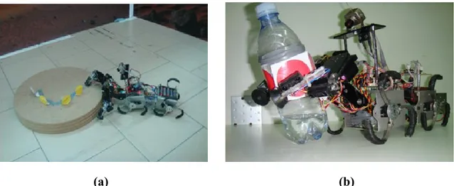
In this work, a bio-inspired robot has been used in the experiments. It is named TriBot, due to the inspiration from the Trinacria (from Greek trinacrios, tries that means three and `
akra that means promoter), the symbol of the Sicily region. Its 3D model and the real
prototype are shown in Figure 2.1.
23
(b)
Figure 2.1: Robot TriBot. (a) AutoCAD design; (b) Physic realization.
The design, the realization and the algorithms developed for the locomotion of the robot taken under consideration were a part of an European project, that is SPARK II "Spatial-temporal patterns for action-oriented perception in roving robots II: an insect brain computational model". The purpose of the project was to develop an artificial sensing, perception and movement that is inspired to the basic principles of the living systems and based on the concept of "self-organization". The project had a duration of three years, from February 2008 to February 2011, and inside this wide project, one of the objective was to study a system able to make the robot autonomous, from the energetic point of view, as much as possible.
The structure of the robot is constituted by two wheel-legs modules, an optimal solution for walking in rough terrains and to overcome obstacles. Moreover, a manipulator was added to improve the capabilities of the system that is able to perform various tasks: environment manipulation, object grasping, obstacle climbing and others.
In this paragraph, we discuss about the mechanical and electronic elements of the autonomous mobile robot developed. In particular, the robot design process and the energy consideration are shown.
24
2.2.1. Mechanical design
The robot has a modular structure; in particular it consists of two wheel-legs modules and a two-arms manipulator. The two wheel-legs modules are interconnected by a passive joint, whereas an actuated joint connects these modules with the manipulator that consists of two legs with three degrees of freedom. To connect the two modules, a passive joint with a spring have been used. It allows only the pitching movement and facilitates the robot during climbing, in fact the body flexion easily allows, in a passive way, to adapt the robot posture to obstacles. Besides, the actuated joint between the two modules and the manipulator allows the last one to assume two different configurations, therefore it can be useful to improve locomotion capabilities when it is moved down (i.e. used as legs) (Figure 2.2.a), while when it is moved up it can make manipulation and grasp objects (i.e. used as arms) (Figure 2.2.b). The whole mechanical structure is realized in aluminum and plexiglass; both materials have been selected for their characteristics of cheapness and lightness.
(a) (b)
Figure 2.2: Different robot behaviors. (a) The frontal manipulator can be used for
climbing and (b) for taking objects.
The mechanical peculiar characteristic of this robot is the design of Whegs: each leg is in fact realized with a tri-spoke appendage and is actuated by a single electric motor. It is a hybrid solution, the result of a study on the efficiency of a wheel-leg hybrid structure; in this way the robot can have the advantages of using legs, in fact it can easily overcome obstacles and face with rough terrains. On the other way, wheel-legs have the shape of wheels; therefore the robot TriBot is able to have a quite smooth movement in regular terrains and so to reach high speed.
25 The spokes can be moved in two different directions; if each spoke faces the convex part toward the motion direction, the movement results to be smoother because the wheel-leg has a quasi continuous contact with the terrain. While, the other configuration is better in overcoming obstacles because it increases the grip with the terrain.
2.2.2. Electrical characteristics
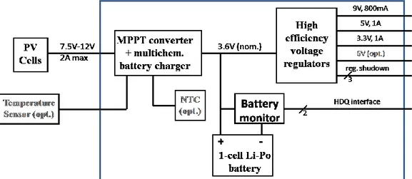
The hardware architecture of the robot TriBot follows the modularity of the structure. A block diagram is shown in Figure 2.3.
Figure 2.3: Functional scheme of the communication architecture.
The hardware structure of TriBot is managed by two microcontrollers that handle motors and sensors distributed on the structure. Furthermore through a computer, using a wireless connection, it is possible to acquire data and send commands generated by a high level control algorithm. To control the robot, two boards based on ATmega128, a low-power CMOS 8-bit microcontroller based on the AVR enhanced RISC architecture [38], connected using a serial bus and a graphical user interface (GUI) have been developed. The main role of the master control board, that is positioned in the backward wheel-legs module, is to control the servomotors that actuate the four wheel-legs and is also used as a bridge between the PC and the other board mounted on the manipulator. The manipulator is controlled by a similar board