Università degli Studi di Ferrara
DOTTORATO DI RICERCA IN
MATEMATICA E INFORMATICA
CICLO XXVICOORDINATORE Prof. Mella Massimiliano
A Web portal to simplify the scientific
communities in using Grid and Cloud resources
Settore Scientifico Disciplinare INF/01
Dottorando Tutore
Dott. BENCIVENNI MARCO Prof. LUPPI ELEONORA
Contents
Contents iv
List of Figures viii
List of Tables x
Introduction xii
1 Grid and Cloud architecture 1
1.1 Authentication . . . 1 1.1.1 X.509 Certificate . . . 1 1.1.1.1 Certification Authority . . . 4 1.1.1.2 Robot certificate . . . 5 1.1.1.3 Personal Certificate. . . 6 1.1.2 Proxy . . . 6 1.1.2.1 MyProxy . . . 7 1.1.3 Identity Federation . . . 8
1.1.3.1 eduGAIN and IDEM . . . 10
1.2 Grid Architecture . . . 11 1.2.1 VOMS . . . 12 1.2.2 WMS . . . 15 1.2.3 Computing Element . . . 15 1.2.4 Storage Element . . . 16 1.2.4.1 StoRM Implementation . . . 18 1.2.5 LFC . . . 18 1.3 Cloud . . . 20 1.3.1 Openstack . . . 22 1.3.2 OpenNebula . . . 22 1.3.3 WNoDeS . . . 23 2 Architecture 25 2.1 Portal . . . 25 2.1.1 Portlet . . . 25 2.1.1.1 Portlet Container . . . 26 iv
Contents v
2.1.1.2 Portal Server . . . 26
2.1.1.3 Liferay . . . 26
2.2 Grid Portal Classification. . . 27
2.3 Portal Architecture . . . 29
2.4 Database. . . 30
3 Authentication and Authorization 33 3.1 Related Works. . . 33
3.1.1 GridCertLib . . . 34
3.1.2 CILogon . . . 34
3.1.3 Terena Certificate Service . . . 34
3.2 Authorization . . . 35
3.3 Authentication . . . 41
3.4 Online CA integration . . . 43
4 Workload Management 51 4.1 Existing solutions . . . 51
4.1.1 gUSE & WS-Pgrade . . . 51
4.1.2 DIRAC . . . 52
4.2 Generic jobs . . . 54
4.3 Workflow . . . 56
4.4 Specific Applications . . . 57
5 Data Management 61 5.1 EMI Data Management utilities . . . 61
5.1.1 LCG utils . . . 61 5.1.2 lfc-* commands . . . 62 5.2 File manager . . . 63 5.3 Upload . . . 65 5.4 Download . . . 67 6 Cloud services 69 6.1 Interactive Cloud Service . . . 69
6.2 Cloud resources for the Jobs execution . . . 73
7 Use cases 75 7.1 ANSYS . . . 76
7.2 FLUKA . . . 79
8 Conclusions and future developments 83 8.1 Conclusions . . . 83
8.2 Future developments . . . 84
Contents vi
B Script for moving files from Grid to Remote Servers 95
C DIRAC multi VO configuration 101
D Portal logical architecture 113
Bibliography 115
List of Figures
1 Portal homepage . . . xiii
1.1 X.509 Certificate structure . . . 3
1.2 X509 Example. . . 4
1.3 Grid delegation . . . 7
1.4 Interaction between MyProxy and Portal . . . 8
1.5 MyProxy used for proxy renewal. . . 8
1.6 Identity Federation model . . . 9
1.7 Map of eduGAIN members . . . 10
1.8 Grid architecture . . . 13
1.9 Interactions between Client and VOMS . . . 14
1.10 Proxy with VOMS extension . . . 14
1.11 Job Types . . . 16
1.12 Storage Element architecture. . . 17
1.13 StoRM architecture . . . 19
1.14 Grid Data Naming . . . 19
1.15 Cloud Topologies . . . 21 1.16 Cloud Architecture . . . 22 2.1 Portlet Container . . . 27 2.2 Portlet architecture . . . 30 2.3 Database schema . . . 32 3.1 Registration - Step1. . . 36 3.2 Registration - Step2. . . 37 3.3 Registration - Step3. . . 38 3.4 Registration - Step4. . . 39 3.5 Registration - Summary . . . 39
3.6 Registration Flow Diagram. . . 40
3.7 Authentication - Organization choice . . . 42
3.8 Authentication - VO choice . . . 42
3.9 Authentication Flow Diagram . . . 43
3.10 Portal architecture with the online-CA . . . 45
3.11 Registration with the online-CA - step2 . . . 46
3.12 CA-bridge interface . . . 47
3.13 Online-CA Flow Diagram . . . 48
List of Figures ix
4.1 gUSE/WS-Pgrade architecture. . . 52
4.2 DIRAC architecture . . . 54
4.3 DIRAC potlet submission . . . 55
4.4 DIRAC potlet monitoring . . . 55
4.5 Workflow structure . . . 56
4.6 gUSE/WS-Pgrade portlet . . . 57
4.7 Specific application portlet . . . 59
5.1 Data Management Architecture . . . 63
5.2 Data Management Interface . . . 64
5.3 Data Management - Upload interface . . . 66
5.4 Data Management - Download interface . . . 68
6.1 Portlet Cloud - SSH Keys management . . . 71
6.2 Portlet Cloud - Image repository . . . 71
6.3 Portlet Cloud - VMs Lists . . . 72
6.4 Portlet Cloud - Web terminal . . . 72
6.5 Data Management Architecture . . . 74
7.1 SPES section in the portal . . . 76
7.2 The portlet for the ANSYS suite . . . 77
7.3 Example of ANSYS Output . . . 78
7.4 The portlet for the FLUKA application . . . 80
7.5 Example of FLUKA Output . . . 81
List of Tables
2.1 VO portal policy summary. . . 28
3.1 Credentials needed for the registration *Case 2 is possible only as proof of concept . . . 36
4.1 Applications in the portal and their status . . . 58
5.1 LCG Utils . . . 62
5.2 lfc commands . . . 62
6.1 Cloud CLI . . . 70
Introduction
The modern scientific applications demand increasing availability of computing and storage resources in order to collect and analyze big volume of data that often the single laboratories are not able to provide. In the last decade, distributed computing models such as Grid and Cloud have proved to be a valid and effec-tive solution. A proof is the Grid model, widely used in the high energy physics experiments. In this scenario also Clouds are showing an increasing acceptance. Although the Grid has been recognized as a valid solution to allow the sharing of computing and storage resources it was restricted principally by physicists users due to its intrinsic difficulty.
The first obstacle to deal with in the use of Distributed Computing Infrastructures (DCIs) is the robustness of Authentication and Authorization (AA) mechanisms. Many user communities complain about the difficulty of handling digital certifi-cates, the mechanism used in Grid to provide a secure computational environment, and the complexity of the Grid middleware. Those factors, along with the steep learning curve, have undermined the wide adoption of those kind of services. In the last three years the Italian Grid Initiative (IGI) has started a process of divulgation and support in order to extend the use of these resources to all dis-cipline, but also activities for simplifying the access to Grid resources, covering both the access step and the use of the middleware components. In particular it has developed a Web portal that aims at facilitating the usage of Grid and Cloud. It hides the complexities and acts as an unique access point for different services such as: federated authentication, job submission, workflows, data management in order to make easier the distributed computing resources usage to name a few. Being the Cloud natively easier than Grid, the majority of the services developed is relative to the Grid, especially for the authentication and authorization mecha-nisms that are the most difficult aspects for the new Grid users.
In order to develop a powerful but sustainable solution, the Web portal has been xii
List of Tables xiii
connected to some already existing services for the workload management or oth-ers internally developed for the authentication and authorization operations and for the data management. This type of solution has two main advantages: the users see only a high level interface hiding them the underlying complexity and the project is sustainable because it relies on several existing services, widely used and well maintained. Our works consists in: configuring correctly the portal and the services used, interconnecting the portal with the external services and devel-oping new ones when needed. Pieces of software are developed only if other valid solutions do not exist or can not be used.
Fig. 1shows the homepage of the Web portal developed. The portal URL is: https://portal.italiangrid.it
Figure 1: Portal homepage
In Chapter 1 we focus the attention on the paradigm of distributed computing, in particular Grid and Cloud infrastructures. The Grid, being at the moment the most usable infrastructure through the portal interface, it is introduced with more emphasis, especially the services that have a main role in the portal architecture. It is described also the Cloud definition and some implementations because the future works on the portal will be oriented in this direction.
Chapter 2 we discuss the authorization and authentication mechanisms
imple-mented in the portal in order to hide the user from these complex aspects. We also explain a study to integrate an online Certification Authority (CA) in the
List of Tables xiv
portal architecture as a proof of concept.
In Chapter 3 it is described which external services have been integrated in the portal architecture to perform different type of computations: jobs, workflows and specific applications.
In Chapter 4 we focus on the data management aspects and the solution developed in order to avoid the users to learn difficult commands to transfer data from their PC to Grid and viceversa.
In Chapter 5 we give some examples how we have used the portal for specific ap-plications, developing scripts and interfaces ad hoc for some communities in order to hide the Grid complexity as much as possible.
In Chapter 6 we explain the services that we are going to use in order to inter-face the portal with the Cloud infrastructures. Two different use cases have been studied: the Cloud resources used in an interactive way or used as computation resources on demand for the job execution.
In the appendixes are shown pieces of code developed for different purposes: the appendix A shows the bash script used to run an application in Grid. In the ap-pendix B there is the code for moving files or directory from the Grid to different remote storage servers using several protocols. In appendix C is shown the DIRAC configuration used to support multi VOs. Moreover in appendix D is shown the portal logical architecture with all the components described in the thesis.
Chapter 1
Grid and Cloud architecture
1.1
Authentication
The authentication is a fundamental point both for Grid and Cloud because it concerns the security aspects. The European Grid Infrastructure is composed of more than 350 Grid sites distributed all over Europe and for these reasons it is obvious that the security is one of the most important topic because a security breach at one of the Grid site can affect a huge number of other sites. Therefore a robust Authentication mechanism is a fundamental component in Grid.
In Grid the authentication mechanism is based on X.509 digital certificates, defined by RFC 5280. In Cloud the authentication method is not univocally defined, it could be used the X.509 certificates [1] yet but also other solutions as the federated identity. In next paragraphs we introduce the basic concepts and services useful to better understand the following chapters. In particular we are going to explain the Authentication mechanism in Grid and the concepts of Identity Federations.
1.1.1
X.509 Certificate
A public key certificate (also known as a digital certificate) is an electronic docu-ment used to identify an individual, a server or some other entity. In this way it is possible to associate an identity with a public key. In cryptography the asymmet-ric encryption involves a public key and a private key associated with an entity that needs to authenticate its identity electronically. Each public key is published,
Chapter 1. Grid and Cloud architecture 2
and the corresponding private key is kept secret. Data encrypted with your public key can be decrypted only with the corresponding private key1.
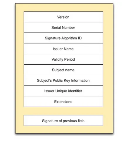
The X.509 is the standard for the digital certificate, it combines a Distinguished Name (DN) with a Public key; the DN is a collection of information about a per-son in a determined context. These information are in the key/value pair format: where the values depend on the CA which signs the certificate itself. The typical fields of a Distinguish Name in a X.509 certificate are: CN: Common Name, O: Organization, OU: Organization Unit, C: Country, ST: State Or Province Name, L: Locality. In Fig. 1.1 is shown the X.509 structure. It follows a brief description of the fields:
• Version is a integer value; the possible alternatives are:
– 0. default (v1)
– 1. if present “Issuer unique identifier” or “Subject unique identifier“ (v2)
– 2. in case of extensions (v3)
• Serial number in an integer value, unique for each CA; it identifies unam-biguously the certificate.
• Signature algorithm ID : it represents the algorithm and the hash function used by CA to signs the certificate (e.g. md5WithRSAEncryption, sha-1WithRSAEncryption).
• Issuer name: Distinguish Name of the CA which has signed the certificate.
• Validity period : it contains the date in which the certificate starts to be valid and the expiration date.
• Subject name: the Distinguished Name of the certificate’s owner (who has the corrispective private key).
• Subject’s public key information: Public key of the certificate’s owner and relative algorithm (es. rsaEncryption).
• Issuer unique identifier : it is used to distinguish univoquely the CA if the same DN is used in two distinct CAs.
Chapter 1. Grid and Cloud architecture 3
• Subject unique identifier : it is used to distinguish univoquely the certificate’s owner if the DN (of the user) it is reused.
• Extensions: the extension are divided in 3 categories:
– key and policy information, for example the certificate utilization scopes, – subject and issuer attributes, for example the subject/issuer alternative
name,
– certification path constraints, for example if the subject can act as a CA.
The hash of these fields is signed by the CA private key.
Figure 1.1: X.509 Certificate structure
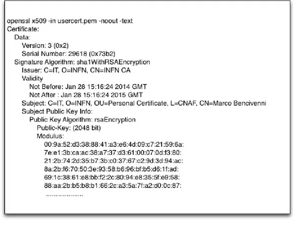
In Fig. 1.2 is shown an example of a certificate. After obtaining a personal X.509 certificate, the user have to store it according to some basic security rules defined by their CA, including:
Chapter 1. Grid and Cloud architecture 4
• storing the encrypted private keys on a local file system only;
• applying for the certificates renewal near the expiration date.
Figure 1.2: X.509 Certificate example
1.1.1.1 Certification Authority
A Certification Authority is a third party entity, public or private, qualified to issue distribute and revoke digital certificates X.509 following certification procedures established by international regulations. The authority issues a certificate used to signs the user’s certificate. The CA software must run in a specialized and safe hardware with the highest physical and logical security measures. Any CA has a Registration Authority (RA) which is the system for the registration and authentication of the users who are able to ask for a certificate.
A CA can be of 2 types: online or offline. The offline CA is completely disconnected from the network and the certificate issue procedure need the physical intervention of a CA administrator. The online CA typically has a front-end connected to the
Chapter 1. Grid and Cloud architecture 5
network and a back-end connected only to the front-end. Being this CA connected to the network it is more exposed than the previous one so the security mechanisms requested to protect it are stronger. Through an online CA a user can obtain a certificate on-demand in an automatic way.
The access to the EGI infrastructure is restricted to certificates provided by CAs accredited to the International Grid Trust Forum (IGTF2) federation. The IGTF
role is to establish common policies and guidelines among its Policy Management Authorities (PMAs) members. EUGridPMA3 is the international organisation
coordinating the trust fabric for e-Science authentication in Europe.
According to the IGTF rules it can exist one IGTF-accredited CA per country per type: for example one CA offline e one CA online in Italy. Moreover the IGTF accepts 2 types of certificate profile:
• Short Living Credential Service (SLCS) SLCS: the certificates issued by a SLCS CA have a maximum lifetime of 11 days.
• Member Integrated Credential Services (MICS) [13]: the certificates issued by a SLCS CA have a maximum lifetime of 13 months.
The IGTF requirements for an on line CA are illustrated in the document for the MICS profile. In particular, the user’s primary identity vetting must be performed de visu, the assessment of the type of vetting done by the users home institutions is done through a specific attribute (eduPersonEntitlement) released by the IdPs. Moreover, the documents specifies that a certificate can be issued only upon an explicit user’s request, that all communications are secure and that the user’s private key is kept on the server for the time strictly needed to complete the process. Two types of certificate can be used in a web portal: robot or personal. In the next paragraphs we explain the difference between them.
1.1.1.2 Robot certificate
The Robot Certificate has been introduced in order to allow unattended services to perform automated Grid tasks on behalf of a person. A Robot Certificate is uniquely associated to a specific application and VO. A typical usage is inside a Web Portal where a group of people submits jobs using the same Robot Certificate.
2http://www.igtf.net
Chapter 1. Grid and Cloud architecture 6
The certificate subject must be the string “Robot” followed by alphanumeric chars without spaces in order to identify the certificate type and in the commonName must be specified the Distinguished Name of the certificate owner. In this way all the job submitted with the same Robot Certificate [2] belong to the same person even if submitted from other people.
Being that a large number of users could performs Grid actions using a single Robot Certificate: if a security incident happens, the robot certificate revocation could have a very high impact because all its users would be unable to use the Grid resources until a new Robot Certificate is generated and associated to the application and VO.
As specified in the EGI Traceability and Logging Policy document [6], the portals which use Robot Certificates need to provide information on who is doing what at any time. They implement a mechanism to continuously track the real identity of the user that is performing Grid operations. Moreover it has to store these information in order to exactly identify the malicious user’s identity in case of security incident.
1.1.1.3 Personal Certificate
A Personal Certificate is a certificate issued to a person by a Certificate Authority only after a de visu identification. In order to perform Grid operations the user must also be registered into one or more VOs. The name reported in the certificate identifies precisely the certificate owner and the certificate can not be used by other people. The portals which use this type of credential do not have to implement a mechanism for identity traceability because users are already using their personal credential so, in case of security accident, only the specified user is banned from Grid.
1.1.2
Proxy
As we have explained above, Grid users have to provide a certificate in order to prove their identity. Anyway, in Grid it is often necessary that a service acts on behalf of the user, this mechanism is known as delegation. Instead of sending the user’s certificate on the net, it is used a proxy certificate that has limited rights. A proxy is a certificate with a shorter lifetime, typically of 12 hours. In order to
Chapter 1. Grid and Cloud architecture 7
create a proxy, a new public/private key pair is created and a new certificate is built. It is signed with the certificate’s long-term private key and it contains the public key using a name with the form of the following example:
/C=IT/O=INFN/OU=Personal Certificate/L=CNAF/CN=Marco Bencivenni/CN=proxy
When a job is submitted, the proxy certificate, the private key for the proxy and the normal certificate (but not the long-term private key) are sent with it. When the job wants to prove its delegated identity to another service, it sends it the proxy certificate and the standard certificate, but not the proxy private key. This information is sufficient to prove that the remote service has the right to use the delegated identity. Proxies usually have a lifetime of only a few hours, so the potential damage is fairly limited4. The Fig. 1.3 shows the steps to create a proxy
certificate and delegation.
Figure 1.3: Grid delegation
1.1.2.1 MyProxy
MyProxy is open source software for managing certificates and private keys. It can be configured to store encrypted private keys with a password chosen by the user [10].
The typical interaction between a MyProxy and a Web Portal is that the portal contacts the MyProxy server to obtain credentials so it can access Grid resources on user’s behalf. The users has to enter his username and password on the portal page, these credential are used by the portal to login to MyProxy on user’s behalf. In this way the portal is authorized to retrieve user’s credential. The schema of this interaction is show in Fig. 1.4.
Chapter 1. Grid and Cloud architecture 8
Figure 1.4: Interaction between MyProxy and Portal5
Another important use of MyProxy is for credentials renewing.
Users can store a proxy credential in the MyProxy Server using the myproxy-init command. Whenever users needs a credential, they can retrieve a short-lived proxy from the MyProxy with a specific command6. In this way it is possible to
access the credentials without needing to copy the real and long user’s certificate and private key between systems, which can be the cause of security problems. The schema of this interaction is show in Fig. 1.5.
Figure 1.5: MyProxy used for proxy renewal
1.1.3
Identity Federation
We are now going to explain another type of authentication not adopted in Grid yet, but used by the portal to authenticate the users. A federation can be con-sidered as an agreement among organizations and resource providers. The organi-zations mutually trust the information exchanged during the authentication and authorization procedures following detailed rules in order to maintain this trusted relationship.
Chapter 1. Grid and Cloud architecture 9
In order to avoid that the users have to authenticate themselves every time they access a service, an Authentication and Authorization Infrastructure (AAI) has been introduced. The task of this infrastructure is to manage the authentication and authorization procedures among the users, their organization and the services offered introducing the federation identity mechanism.
Figure 1.6: Identity Federation model
The Security Assertion Markup Language (SAML) is the protocol used for ex-changing authentication and authorization data between parties. In particular it is an XML-based open standard data format, and it is used to exchange data be-tween the service that manage the user’s identity and a generic service provider. Its principal scope is to provide the Single Sign On (SSO) property.
In the SAML protocol are defined three roles: the principal (the user), the Identity Provider (IdP), and the Service Provider (SP) as shown in Fig. 1.6. The typical scenario is:
1. the principal requests a service from the SP;
2. the SP requests an identity assertion from the IdP;
3. the principal authenticates himself on the IdP which issues an assertion to the SP;
Chapter 1. Grid and Cloud architecture 10
4. the SP, on the basis of this assertion, decided whether the principal can access to the services.
In a federation there are many SPs and IdPs: one IdP may provide SAML asser-tions to many SPs and viceversa one SP may rely on and trust asserasser-tions from many IdPs.
Shibboleth and SimpleSamlPHP are SAML implementations used to build SP and IdP. In particular while Shibboleth is written in Java and uses Tomcat as container in which the IdP runs, SimpleSamlPHP is written in PHP. At present several Iden-tity Federations exist, in the next paragraph we introduce 2 of them because they have been interfaced to the portal.
1.1.3.1 eduGAIN and IDEM
eduGAIN is a service developed within the G´EANT project and its scope is to interconnect identity federations around the world, simplifying access to services and resources for the global research and education community. eduGAIN co-ordinates the elements of the federations and provides a policy framework that controls this information exchange.
Figure 1.7: Map of eduGAIN members7
eduGAIN has 17 active participant federations (as shown in Fig. 1.7), one of which is IDEM: the Italian identity federation of universities and research institutes for
Chapter 1. Grid and Cloud architecture 11
authentication and authorization. At present IDEM is composed of 74 IdPs and 90 SPs.
1.2
Grid Architecture
The Grid infrastructures were born and are still being used to face one of the most challenging scientific collaborations, such as the ones running the experiments at CERN’s Large Hadron Collider (LHC8). The Grid relies on advanced software,
called middleware, an interface between resources and applications. A typical usage scenario is: many users of different organizations geographically distributed (Virtual Organizations VOs) requesting high computational and storage capacities and collaborating with each others where the computational resources (computing and storage) belongs to different institutions but are transparently accessible. The users join a VO, each VO shares Grid resources with other VOs accordingly to several policies.
There are several middleware distributions: gLite, Arc, Unicore, etc. The rest of this document we consider only the gLite solution which was developed in the context of the Enabling Grids for E-sciencE (EGEE) project [28]. At the end of EGEE, the development has been carried on by the European Middleware Initiative (EMI) [25] as components of the EMI distribution. Now its key services are maintained as independent projects by the interested research institutions. In order for the user to exploit and share these resources, the gLite middleware is composed of different services. Some of these are:
• User Interface (UI): the user entry point.
• Workload Management System (WMS): a set of services having the scope to find the best available computing element where to submit user’s job.
• Logging and Bookkeeping (LB): it keeps track of user job execution in terms of status: Ready, Scheduled, Waiting, Running, Done.
• Computing Element (CE): it is the service responsible of the computation tasks. It is the entry point to several types of servers handled by a job queue management system.
Chapter 1. Grid and Cloud architecture 12
• Worker Node (WN): the servers where jobs are executed and managed by the CE queue management system.
• Information System (IS): the service for maintaining information about the available Grid resources and their health status.
• Virtual Organization Management Service (VOMS): the service for manag-ing the authorization to use the Grid resources. Furthermore VOMS allows the VO managers to define different access rights to VO’s resources.
• Storage Element (SE): the service responsible to manage Grid files.
• LCG File Catalogue (LFC): it offers a mechanism for users and jobs to easily locate the files stored in the SEs.
• Site-BDII : it collects the information gathered by the various services at a site level.
• Top-BDII : it collects the information from different sites.
Being some of these services directly connected to the portal or used by it, in the next paragraphs these will be described in more detail.
Fig. 1.8 shows the Grid architecture and the components interaction. Although the Grid Middleware services should hide the users from the underlying infrastruc-ture complexity, it is common belief that these services are not easy to use. The middleware services are usually accessed via the Command Line Interface (CLI) but while this is a trivial tasks for expert users, it may be very complex for not skilled user communities.
1.2.1
VOMS
The VOMS is the Grid system for managing VO user authorization information [11].
VOMS provides a database for sorting users into groups and keeping track of their roles and other attributes. These information are used to issue trusted attribute certificates and VOMS extension which are used in the Grid environment for au-thorization purposes. Through a command line available in the UI, users can generate a local proxy credential based on the user’s information in the VOMS
Chapter 1. Grid and Cloud architecture 13
Figure 1.8: Grid architecture
database. At the time the proxy is created, one or more VOMS servers are con-tacted and they return an Attribute Certificate (AC) which is signed by the VO and contains information about group membership and any associated roles within the VO.
The information exchange between Client (UI) and the VOMS Server follows the workflow shown in Fig. 1.9 and described by the following steps:
1. Mutual authentication between client and server.
2. Client sends a signal request to server that checks the user’s identity and if the request is syntactically correct.
3. Server signs the authorization information and returns it back. The Client checks the consistency and validity of the information returned, creates a proxy certificate that includes the information returned by the VOMS servers.
Chapter 1. Grid and Cloud architecture 14
Figure 1.9: Interactions between Client and VOMS
At the end of these process the credential includes the basic authentication in-formation (Grid proxy credential) but also group and role inin-formation from the VOMS server, as shown in Fig. 1.10. The VO administrator can assign roles to user and manage user’s information.
Chapter 1. Grid and Cloud architecture 15
1.2.2
WMS
The WMS is the middleware component responsible for submitting and managing jobs in Grid.
WMS typically receives requests for a job execution from a client (UI for example) and, on the base of job requirements, finds the most appropriate resources, submits the job to the resource and follows the job submitted until its completion. In case of failure the WMS can also resubmit, if the job description requires it [20]. The WMS is able to handle different job types (shown in Fig. 1.11):
• Batch: single job.
• Directed Acyclic Graphs (DAG): a set of jobs where the input/output/exe-cution of one of more jobs may depend on one or more other jobs.
• Parametric Jobs: multiple jobs with one parameterized variable,
• Collections: multiple jobs with a common description but each one indepen-dent from the others.
• Parallel jobs: a set of jobs each one dependent from the others commonly used to handle the communications between tasks in parallel applications.
Jobs are described via a flexible, high-level Job Definition Language (JDL).
1.2.3
Computing Element
CE is the services that provides an uniform interface to the Grid to allow the jobs to be executed in a Local Resource Management System (LRMS), like Load Sharing Facility (LSF), Portable Batch System (PBS) or Sun Grid Engine (SGE). The Computing Resource Execution and Management (CREAM) Service is a lightweight service for job management. CREAM accepts job submission requests and other job management requests (e.g. job cancellation, job monitoring, etc) via WMS or directly from the end-user. The job submitted directly are described with the same JDL language used to describe the jobs submitted to WMS. Once the job has been received by the CE it is scheduled on the LRMS. It waits there for the proper resources, based on the queue, user privileges, etc to be free and then it is sent to a WN. The WN is essentially a UI that includes commands
Chapter 1. Grid and Cloud architecture 16
Figure 1.11: Job Types
to manipulate the jobs and has access to a software area where the required pro-grams are installed the. The job is executed by mapping an appropriate local user to the Grid user.
1.2.4
Storage Element
A Storage Element is the Grid service that allows the users to store and manage files in the storage resources deployed in the Grid site. Using standard interface it is able to provide the users a uniform interface hiding them from the heterogeneity of the resources: disk servers, Storage Area Network (SAN), tape server, etc. As shown in Fig. 1.12, in order to make the storage available in a Grid infrastruc-ture, the storage resource is wrapped by the storage service.
In gLite several implementations are available:
• Storage Resource Manager9 (StoRM): it takes advantage of the parallel file
systems to access disk areas [23].
• dCache10 : by means of disk buffer, a server acts as frontend for a complex
mass storage system.
9http://italiangrid.github.io/storm/ 10http://www.dcache.org/
Chapter 1. Grid and Cloud architecture 17
• Disk Pool Manager11 (DPM): a lightweight solution for disk storage
man-agement.
The standard interface of all these implementations is the Storage Resource Man-ager [21] (SRM) which is responsible of interacting with the underlying storage hiding the implementation details and providing a Grid interface to the outside world. SEs also use standard transfer mechanisms for remote access such as the File Transfer Protocol in Grid Computing Networks12(GridFTP) that grants performance, secure connection, reliable data transfer, and is optimized for high-bandwidth wide-area. The data in a SE can be accessed through several standard protocols: Remote File I/O (rfio) to directly access the remote files in the SE, Data Link Switching Client Access Protocol13 (dcap) and file.
Figure 1.12: Storage Element architecture
As well as for the other services, the users must have the valid credentials to access the SE. The system can allow or deny access and manage the space with quotas, prevent the deletion of file with pinning, preallocate a storage space per VO with space reservation and set a specific lifetime on the file.
The Grid service that manage the transfers is the File Transfer Service (FTS) [33]. It interacts with the SRM source and destination using the gridFTP protocol.
11https://www.gridpp.ac.uk/wiki/Disk Pool Manager 12http://www.ogf.org/documents/GFD.47.pdf
Chapter 1. Grid and Cloud architecture 18
This allows the transfer of huge amount of data using multiple streams, queue of transfers, detection of errors and rollback.
1.2.4.1 StoRM Implementation
StoRM solution has been designed, developed and maintained by the INFN-CNAF development team. It has been designed in order to take advantage of the high performance of parallel file systems used in Grid. Several file system are supported: General Parallel File System14 (GPFS), Lustre15, Posix FS16 etc.
The StoRM architecture (shown in Fig. 1.13) encompasses different elements. It is possible to deploy each one of them in a different server:
• Front-end: it exposes the SRM interface (written in C++).
• Back-end: it executes the SRM requests (written in Java).
• Database: it stores the requested data and StoRM metadata (MySQL based).
1.2.5
LFC
A relevant problem in a distributed architecture as Grid is to uniquely identify a file but also identify replicas of the same file in different location and with different names. Each file in Grid is univocally identified by a Global Unique Identifier (GUID), a non-human-readable fixed-format string that identify an item of data. Each file can be replicated in different locations and each replica is identified by a Site URL (SURL) or Physical File Name (PFN). The Transport URL (TURL) provides the necessary information to access a file in a SE; it is a string composed by the access protocol and the temporary locator of a replica.
To access the desired file the users define the Logical File Name (LFN). The LFN, as the GUID, is independent from the location of the file.
LFC servers are databases containing a list of correspondences between LFN, GUID and SURL. When accessing a SE, the standard protocols use the TURL address, given upon request by the SE itself, to write or retrieve a physical replica.
14http://www-03.ibm.com/systems/software/gpfs/ 15 http://users.nccs.gov/ fwang2/papers/lustre report.pdf 16 http://www.opengroup.org/austin/papers/posix faq.html
Chapter 1. Grid and Cloud architecture 19
Figure 1.13: StoRM architecture
Chapter 1. Grid and Cloud architecture 20
1.3
Cloud
By definition the Cloud computing is a model to conveniently enable on-demand network access to a shared pool of configurable computing resources (e.g.: net-works, servers, storage, applications, and services) that can be rapidly provisioned and released with minimal management effort or service provider interaction. The Cloud is another type of distributed computing infrastructure over the net. Using the Cloud, the users connected to a Cloud Provider which can perform op-erations as use of computing or storage resources and retrieval of data or software through a web browser.
A user can execute remote software and store the resulting data in the online storage made available by the provider.
It is possible to distinguish 3 main topologies of Cloud computing services:
• IaaS (Infrastructure as a Service) - It consists of using remote hardware resources. This type of Cloud is similar to the Grid paradigm but with a main difference: the resources used are available on demand, they are not preassigned independently of their utilization (e.g Amazon EC2).
• PaaS (Platform as a Service) - On a remote server is executed a software platform that could be composed by several services: programs, libraries etc (e.g Google App Engine).
• SaaS (Software as a Service) - It consists of using software installed in a remote server through a web server (e.g Google Apps).
In the IaaS the Cloud provider manages everything from the data centers, network, storage, servers, and operating systems–leaving the customer to manage their own applications and data. In other types of Cloud services, the Cloud provider could manage the entire system all the way up to and including applications and data17.
Fig. 1.15 shows a high-level view of the provider and customer roles for IaaS, PaaS, and SaaS.
The Cloud Computing system encompasses 3 main actors:
• Cloud provider: the entity who offers the services (virtual servers, storage, applications), usually on the base of a ”pay-per-use” model.
17
Chapter 1. Grid and Cloud architecture 21
Figure 1.15: Cloud Topologies
• Administrator Client: the entity who chooses and configures the services. Usually it is his task to install the necessary software for the final user.
• Final Client: the entity who uses the services opportunely configured by the administrator client.
In some use case the administrator client and the final client could be the same entity: for example a client uses a storage service to backup his data and it is also responsible for configuring the service itself.
From an architectural point of view the Cloud Computing consists of one or more physical servers, generally in a high availability configuration and located in the data center of the service provider.
As shown in Fig. 1.16, the Cloud provider offers interfaces to catalog and manage the available services. The client administrator uses these interfaces to select the requested service (for example a complete virtual server or only the storage com-ponent) and to administer it (configuration, activation, deactivation).The client uses the service preconfigured by the administrator. For the final user the features of the physical servers are not relevant.
The Cloud solutions are various, in the next paragraphs we describe only those that the portal has been interfaced to.
Chapter 1. Grid and Cloud architecture 22
Figure 1.16: Cloud Architecture
1.3.1
Openstack
OpenStack18 is a Cloud-computing project that acts as IaaS platform. It is free
and open-source software released under the terms of the Apache License19. The
project is managed by the OpenStack Foundation. More than 200 companies have already joined the project.
The software has a modular structure composed of a series of interrelated compo-nents that control pools of processing, storage, and networking resources through-out a datacenter, able to be managed or provisioned through a web-based dash-board, command-line tools, or a RESTful API.
1.3.2
OpenNebula
OpenNebula20 is an open source Cloud management toolkit that can be used to build different types of Cloud infrastructures. It is very widespread, has a modular structure and is able to scale from a single node cloud to thousands of physical nodes. OpenNebula manages storage, network, virtualization, monitoring, and
18https://www.openstack.org/
19http://en.wikipedia.org/wiki/Apache License 20http://opennebula.org/
Chapter 1. Grid and Cloud architecture 23
security technologies to deploy virtual machines on distributed infrastructures, combining both data center resources and remote cloud resources.
1.3.3
WNoDeS
Worker Nodes on Demand Service (WNoDeS) [24] is a Cloud solutions developed by INFN and released as a service in EMII. It uses a batch system, integrated in a local farm, to define the resources allocation policies; the batch systems supported are: IBM Platform LSF, Torque/Maui, SLURM. A study to integrate some com-ponents of OpenStack inside WNoDeS is in progress. An important feature, called mixed mode21, is the possibility to manage jobs that use physical resources and
virtual resource at the same time on the same hardware.
Chapter 2
Architecture
2.1
Portal
Before describing in detail the architecture of the portal developed, we introduce some concepts: a general defenition of web portal and which are its components. In the subsequent paragraphs we describe the type of Grid portal and we explain in detail the architecture of the one developed.
A web portal can be considered as a set of web pages in which the contents are com-posed of information originated from different sources and displayed in a uniform way. Usually, each source has its dedicated area on the web page for displaying information (the portlet); often, the user can choose which information to display. Modern Web portals offer several services such as e-mail, news, information from databases and even entertainment content. The features available may be re-stricted in case of authorized and authenticated users (employee or member) or anonymous site visitor.
2.1.1
Portlet
A portlet is a Java technology to develop modular component that are managed and displayed in a web portal. Portlets produce fragments of markup code (HTML, XHTML, WML) that are aggregated into a portal. Typically a portal page is composed of a collection of single portlet and the same portlet can be used in different pages. Through the portlet it is possible to build dynamic contents and
Chapter 2. Architecture 26
manage the contents settings.
Portlet standards are JSR168 [8] and JSR286 [9] and enable software developers to create portlets that can be reused into any other portal that support the standards.
2.1.1.1 Portlet Container
The portal container is the component responsible to manage the single portlet instance and the distribution of the code fragments generated from the portlet to the portal server where they are aggregated.
The portal container is responsible for the instantiation of the methods to manage the portlets lifecycle and to provide them the correct execution environment
2.1.1.2 Portal Server
A portlet is a single web element. In order to create a web portal page it is necessary a component that aggregates all the fragments code generated by the portlet that need to be shown in the same page, this task is carried out by the Portal Server. The portal server is responsible for the communication with the portal container of all user’s request done through the web portal page To sum up the portal container builds the web page contents (a content for portlet), while the portal server aggregates all these contents in a single page providing a uniform style.
There are several solution that offers portal servers/containers, commercial and opensource like: Liferay, GridSphere, iGoogle etc. In the next paragraph we describe in more detail the Liferay solution because it is the one chosen to build the portal.
Fig. 2.1 shows the web portal architecture and how the components described (portal container, portal server and portlet) interact with each other to create a dynamic web page.
2.1.1.3 Liferay
Liferay1 is a free and open source portal written in Java and distributed under
the Lesser General Public License (LGPL). It is worldwide distributed and used
Chapter 2. Architecture 27
Figure 2.1: Portlet Container
by thousands of organizations and company and it is a leader among the open source portal. Liferay is composed of an engine and applications executed by the engine. it provides also an easy to use development framework for new applications or customization. New developed applications can be integrated with the native Liferay applications. Users access native and new applications as the same set. It provides natively 60 portlets with general functionalities: content manager, wiki, forum, blog and many others. It supports the JSR168 and JSR286 portlet standards and utilities as Service Builder to build automatically interfaces for database. The use of standards makes easier and faster the implementation of new functionalities and also the reuse of the same portlets on other portals that use the same technology.
2.2
Grid Portal Classification
The Virtual Organisations Portal Policy [4] is the document produced by the EGI Security Policy Group in which portals are grouped in different classes according to the executable code, executable parameters and the input data provided by the
Chapter 2. Architecture 28
Portal Class
Credentials Executable Parameters Input
Simple one-click
Robot Certificate provided by portal
provided by portal
provided by portal
Parameter Robot Certificate /
Personal Cerificate provided by portal chosen chosen from repository Data pro-cessing Robot Certificate / Personal Cerificate provided by portal chosen provided by user Job man-agement
Personal Certificate provided by user
provided by user
provided by user
Table 2.1: VO portal policy summary.
users or portal. There are four portal classes: Simple one-click, Parameter, Data processing, Job Management. Each portal class allows a different set of actions:
• Simple one-click portals: the submitted jobs use executable codes, parame-ters and input data provided by the portal and can not be modified by the users.
• Parameter portals: the submitted jobs use executable codes provided by the portal. The user can only choose parameters from a list and select input data from a list of files saved in the Portal repository.
• Data processing portals: the submitted jobs use executable codes provided by the portal. The user can only choose parameters from a list and provide personal input data.
• Job Management portals: the submitted jobs use executable codes provided by the portal. The user also choose parameters and provide personal input data
All portals operated by (or on behalf of) a VO, which comply with the general EGI Virtual Organisation Operations Policy [5], have to deal with the limitations defined in the VO Portal Policy. Table 2.1 describes the user privileges and the required credentials for each portal class.
In particular the portal developed belongs to the ”Job Management” class since all users provide their personal certificate. In this way the users can provide their
Chapter 2. Architecture 29
computational jobs with the executables, input data and parameters. For this reason the portal is as flexible and powerful as a Grid UI. Other solutions, such as, Science Gateways [34], relying on the Robot Certificate, belong to the Data Processing class detailed in Table 2.1. Within these portals users must provide the input data while the computational job executable and parameters are fixed and pre-configured within the portal.
2.3
Portal Architecture
The IGI Web portal is based on the Liferay Framework2 and it has been designed and developed to allow an easy and fast access to Grid and Cloud resources. The main tasks of this kind of portals are to hide and automate some procedures that for not expert users could be too complex, such as: authentication mechanism, job submission and monitoring, data transfer etc. Moreover it is also possible to improve some Grid functionalities that the normal gLite UI is not able to offer such as: workflow and specific application submission, Cloud integration etc. In the next chapters, each of these functionalities will be described in detail. Being the portal based on Liferay Framework, it grants a modular and flexible structure. The portal modules are the portlets and each one of them implements a specific function. This modular structure makes very simple to extend the portal functionalities by simply adding new portlets. Fig. 2.2 shows the overall portal architecture where dark box are third part components while light box are the components we developed.
The Web portal is the high-level interface that hides the underlying complexity and through which users can interact with the connected services running in the background. In the center of Fig.18 there is the portal composed of several blocks, the portlets, that implement the interaction with external services which are:
• MyProxy and VOMS for storing credentials and requesting VO attributes.
• IdPs for managing user authentication,
• CA-Bridge to request the creation of certificates on demand from an online-CA,
Chapter 2. Architecture 30
Figure 2.2: Portlet architecture
• Grid and Cloud services for requesting computing and data resources.
Some of these services are solution already existing and widely used, the reuse of existing and maintained solutions is key for its sustainability.
2.4
Database
An additional MySQL database, called Portal DB, has been added to the default Liferay DB. The Portal DB is used to collect user’s information. Not only does it store user’s personal data such as name, surname and mail, but also data concern-ing the Grid and Cloud like certificate information and VOs membership. These information as described in the next chapter are collected during the registration phase and and are validated before being recorded in the database.
Chapter 2. Architecture 31
• userInfo: this table collects the personal user information, through an ex-ternal key it is possible to store the information if the user has completed the registration procedure
• certificate: this table collects the informazioni about user’s certificate. The tables has an external key to link the certificate to the user identifier. The data collected are: subject, issuer and expiration date and not the whole certificate itself for security reasons. In addition to these information, here is also stored the username used to save the user’s proxy certificate in the MyProxy server (section 1.1.2.1).
• VO : this table collects the information about the VOs supported.
• userToVO : this table allows to collect relations among 3 entities: userInfo, VOs and certificate. The information saved in each tuple are: the user’s VO and the user’s certificate. Moreover, since a user for each VO can be a member of more groups and have more roles, these information are saved here.
• notify: this table collects the information about the proxy lifetime in order to notify the users, some hours before the proxy expiration and give them enough time to renew it in case of running jobs.
• sshKeys: this table collects the keys pair, in encrypted form, used for the connection to virtual machines managed in the Cloud section.
Fig. 2.3 shows the Portal DB schema.
The database has been designed to be useful during the registration phase in order to help the user with dynamic information in drop-down menu on the base of his choices. In appendix D is shown a detailed portal architecture with all the components described in the next chapters.
Chapter 3
Authentication and Authorization
Authorization and Authentication processes in the portal are interconnected: the mechanism of the authentication depends on some choice made during the Regis-tration and one step of the RegisRegis-tration uses the authentication mechanism. For this reasons it is not completely correct to describe one before the other. We have chosen to introduce first the Authorization then the Authentication because the first time users access the portal they have to register themselves proving all the necessary credential, the next times they only have to perform the authentication. For both these aspects we have tried to simplify the procedures, moreover we have done a study to integrate an online-CA in order to provide certificate on-demand.
3.1
Related Works
Before the beginning of the work, several existing solutions which provide on-demand certificate creation, have been examined in order to understand if one of these solutions could be adopted. The softwares analized were: GridCertLib1 [7],
CILogon2 and Terena Certificate Service3. Unfortunately, none of these solutions
was completely satisfactory for the reasons explained in the next paragraphs.
1https://code.google.com/p/Gridcertlib 2http://www.cilogon.org
3http://www.terena.org/activities/tcs
Chapter 3. Authentication and Authorization 34
3.1.1
GridCertLib
GridCertLib is a Library developed in SWITCH 4 and is based on short-lived (11
days) certificates. Every time the users login on to the portal, using their federation identity, it contacts a SLCS online CA in order to provide on-demand new personal certificate. The weakness is that jobs longer than 11 days would fail. To allow users to submit jobs longer than 11 days, the portal has to implement a mechanism to trace any jobs and when they are near to expiration, it has to notify the users to refresh their credentials. This is the main reason why GridCertLib has not been considered as a good solution. This issue could be addressed by adopting long-lived credentials (13 months) in this way the users should be notified for example one month before the expiration of their credentials to renew them through the portal interface and this operation would be only once a year.
3.1.2
CILogon
The CILogon is the solution developed by University of Illinois. It provides dif-ferent types of long lived certificates (11 months) based on the authentication mechanism used to request the certificate. Users can obtain an openID certificate using weak authentication (e.g., their Google account) but these certificates is not accredited by EUGridPMA so they can be used only on local resources. The U.S. students and researchers, who are members of the InCommon federation5 and are identified with a specific Level of Assurance (LoA)6, can obtain ”silver” certificates which are recognized in EUGridPMA. Here the problem lies in the fact that this service is based on the concept of LoA that is implemented only in the InCommon Federation (U.S.)
3.1.3
Terena Certificate Service
The Terena Certificate Service is the solution developed on the context of the Geant Project. It consists of a Web portal where the users can authenticate themselves using their federated credentials and then obtain X.509 credentials. Although in this way the users can obtain easily a Terena personal Certificate (13
4https://www.switch.ch
5http://www.incommon.org/federation 6http://www.incommon.org/assurance
Chapter 3. Authentication and Authorization 35
months of validity) they have yet the problem to manage it because the enrollment certificate process contemplate that the certificates have to be saved locally (i.e on the browser) and finally uploaded to portal. This procedure is quite unfriendly for many users and also browser-dependent. It would be preferable if the online-CA and portal would be directly connected in order to hide completely the users of certificate management complexity.
3.2
Authorization
Now we are going to explain the Authorization mechanism implemented in the portal. The first access to the portal, the so called “Registration”, is the most im-portant phase because users have to prove they have all the necessary requirements to access Grid or Cloud services and the Portal has to register this information in a permanent way in order to automatically configure the correct user’s environment every time the users log in. Users must provide the following information:
• a X.509 certificate;
• a VO membership;
• the IdP to which they belongs.
The portal trusts: the X.509 certificate issued by the CAs that are member of EU-GridPMA, the VO recognized by the EGI project and all the IdPs belonging to the EDUgain federation plus one additional IdP embedded into the portal (Portal IdP), which is for the exclusive use of the Portal itself. In future it will be possible to trust other federations, at the moment eduGAIN covers the majority of the institutes involved in the EGI project.
For the user with only some of these credentials the portal can provide the miss-ing ones: Table 3.1 summaries credentials combinations necessary to successfully conclude the registration phase (i.e. x=absent, o=present).
Users who have a valid X.509 personal certificate and a VO membership can use the portal. If they are already registered in a trusted IdP (case 3 in Table 3.1), their personal information are retrieved from the IdP, otherwise (case 1 in Table
Chapter 3. Authentication and Authorization 36
Case IDP member X.509 certifi-cate
VO
1 x o o
2 o x x
3 o o o
Table 3.1: Credentials needed for the registration Case 2 is possible only as proof of concept
name, email address, institute) from their certificate and registers him/her in the Portal IdP using those information.
The registration phase consists of 4 steps:
• Step 1: Retrieve personal data from the IdP By clicking on the ”Registra-tion” button, users are automatically redirected to a page where they can select their institute (Fig. 3.1). In case it is in the list, they are automatically redirected to their institute’s IdP login page where they have to insert their personal credentials. The portal retrieves the personal information such as first and last name, email address and institute from the IdP. If the institute is not in the list, users have to select ”the other institute” option. Then they are automatically redirected to the second step of the registration.
Figure 3.1: Registration - Step1
• Step 2: Certificate upload If users already have a personal certificate they can upload it to the portal through an encrypted channel and type the passphrase necessary to decrypt it. The web interface to do these actions
Chapter 3. Authentication and Authorization 37
is shown in Fig. 3.2. The portal at this point starts a set of subsequent actions: saves it in a reserved area of the local file system, does not store the passphrase but uses it to decrypt the certificate, creates a proxy certificates Grid Security Infrastructure (GSI) compliant with the lifetime of the cer-tificate [12], encrypts the proxies with a random password auto-generated, saves the encrypted proxies in a dedicated MyProxy Server. The credentials saved in this server last as the original ones so it is called MyProxy Server (long) to distinguish from another MyProxy used to store shorter credentials called MyProxy Server (short). Once the proxy is saved in MyProxy server the original certificate is deleted. If the whole procedure ends successfully, the Portal registers the user’s certificate information (such as DN, expira-tion time, subject, issuer and proxy username) in the Portal DB. In case the user’s organization is not in the list of the trusted IdPs, the information retrieved in this step are used to register them in the portal IdP.
As shown in Table 3.1, users who do not have a valid certificate can not use the portal components. To upload a personal certificate we follow the EUGridPMA guidelines specified in the document “Protection of private key data for end-users in local and remote systems” chapter 2.2 point 3.
We then upload an encrypted personal certificate, in a protected network and we store it only for the few seconds necessary to create the proxy. All the connections are SSL/TSL encrypted. All the web authentications are shibboleth based. The passphrases requested to the user in order to decrypt the user certificate is kept in a non-swappable memory area in clear text and only for the time necessary to complete the procedure and then deleted.
Chapter 3. Authentication and Authorization 38
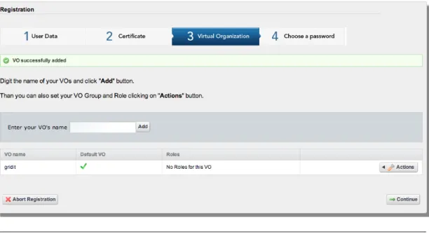
• Step 3: Declare the VO membership Users have to declare their VOs mem-bership. The portal checks the consistency of this declaration querying the VOMS server through the VOMS API. If this operation ends successfully, users can also set their roles and groups for each VO they belong to and set a default VO. In case of more VOs declared, the default VO will be the first VO in the drop-down menu used to choose which VO to use. All these information are stored in the portal DB.
All these actions are possible through the web interface shown in Fig. 3.3.
Figure 3.3: Registration - Step3
• Step 4: Encrypt credentials Users must choose a personal passphrase to encrypt their credentials. This passphrase is not saved in the portal DB. The portal replaces the old proxy passphrase, randomly generated during the second step, with this new one. This passphrase is valid until a new certificate is uploaded.
This passphrases is also kept in a non-swappable memory area in clear text and only for the time necessary to complete the procedure and then deleted. The web interface to do this action is shown in Fig. 3.4.
After successfully completing all the registration steps, users are redirected to a summary registration page (called “MyData”) shown in Fig. 3.5and then can use the portal services.
Chapter 3. Authentication and Authorization 39
Figure 3.4: Registration - Step4
Figure 3.5: Registration - Summary
If the registration procedure is interrupted after the first step, it can be resumed on the following login. The registration procedure can be carried out also setting none VO. In this case users are registered but only when they add a VO Membership in MyData they will be allowed to use all the portal services.
The same portlet used for the registration phase is also used to make some changes during the normal use of the portal, such as adding new VO memberships, adding a new role or group for a VO, or updating the certificate when approaching the expiration date. In this page there is also a section for advanced setting where the users can choose 3 parameters:
Chapter 3. Authentication and Authorization 40
• default proxy lifetime, from 12 hours to 7 days (default value is 2 days that is a good compromise between security and usability);
• if they should receive an email notification when the jobs submitted change the status (default value is “yes”);
• if they should receive an email notification when the proxy is near expiration only if the user has jobs in running state (default value is “no”).
Fig. 3.6 shows the four registration steps in detail.
Figure 3.6: Registration Flow Diagram
Chapter 3. Authentication and Authorization 41
3.3
Authentication
The portal adopts a federated authentication mechanism based on the SAML protocol. This choice has a double advantage: it allows the users to utilize the credentials stored by their organization’s IdP and the portal does not have to store sensible data in its database. Unfortunately Liferay does not support the SAML authentication natively, it supports the Central Authentication Service7 (CAS)
instead. To overcome this issue Casshib8 has been used. This software enables the
CAS server to act as a Shibboleth service provider. We have configured Liferay to use the CAS authentication while, in background, Casshib translates the CAS requests in Shibboleth requests in order to take advantage of the IdP federation. The authentication mechanism in the portal consists of two steps.
Step 1: federated authentication.
1. Users, through the ”Sign In” button, are redirected to a web page where they have to choose their institution or ”Portal IdP” in case their institute is not in the list (Fig. 3.7 shows this page).
2. Users are then automatically redirected to the IdP login page where they must insert their credentials.
3. The portal checks in its database if the users is already registered.
4. If users are already registered on the portal, they are redirected to the main portal page otherwise they are redirected to the registration page.
Step 2: Grid credentials retrieval.
6. Users must select a VO from a menu which lists all the VOs they declared to be part of and insert the passphrase set during the registration phase for the credential encryption as shown in Fig. 3.8.
7. The portal retrieves a proxy by querying the MyProxy Server (long) server. If the proxy is not in the Certificate Revocation List, the portal saves it in an appropriate Portal directory and its lifetime is set to 7 days.
7http://www.jasig.org/cas
Chapter 3. Authentication and Authorization 42
Figure 3.7: Authentication - Organization choice
Chapter 3. Authentication and Authorization 43
8. The portal then makes a copy of this proxy to the MyProxy Server (short) that will be used by the WMS to renew the proxy if necessary.
9. According to the selected VO the portal contacts the appropriate VOMS server in order to add VOMS extension to the short-lived proxy. The proxy with VOMS extensions is called voms-proxy and is the only proxy ever trans-mitted to the Grid. The VOMS extension lifetime is limited by the VO pol-icy. For example, if a user sets N equal to 4, the portal requests a VOMS extension of 4 days. In case the VO policy only allows the extensions of 24 hours, the portal shall renew the VOMS extension every 24 hours.
Fig. 3.9 shows each step of the authentication in detail.
Figure 3.9: Authentication Flow Diagram
(red arrow indicate a user actions, black arrow indicate a system action)
3.4
Online CA integration
As highlighted during the introduction, the request of a personal certificate and its management often represents an issue for not ITC expert users and none of the
Chapter 3. Authentication and Authorization 44
solutions available up to now satisfies completely their requirements.
As a proof of concept we have designed a solutions to overcome this limitation including in the portal architecture an Online CA which provides X.509 certificates MICS profile on the basis of a federation identity (federation acts as RA) and a service (CA-Bridge) to manage these certificates on behalf of the users.
This solution is useful for users without an X.509 certificate but member of a trusted IdP (case 2 in Table 3.1). Using the infrastructure that we are going to describe, users could get a proxy to operate on the Grid through the IGI portal in a transparent way. During the registration phase at step 2 in the previous section (3.2), the portal could provide the option to ask for a certificate.
Fig. 3.10shows the role of the Online CA and CA-bridge in the portal architecture. Users can interact directly with the Web Portal for Grid and Cloud tasks as well as with the CA-Bridge for the certificate management services but not with the Online CA because it is protected by a two-levels firewall. The CA-Bridge service is the only one that can interact to the CA to apply for a certificate on behalf of users and then automatically stores the certificate in the MyProxy server. The encrypted long-term proxy is stored into the MyProxy server, while a delegated short-term proxy is available whenever needed for the Grid tasks. The CA-Bridge, the MyProxy server and the Online CA are the fundamental components of a certificate provisioning service integrated in the portal framework. To implement the Online CA it has been used an open source software, EJBCA9, while the CA-Bridge has been completely developed by us; both these components are Java based.
Certificates are issued according to the following workflow depicted in Fig. 3.13
(each number of this list has a correspondence in the figure):
1. By clicking on the ”Registration” button, users are automatically redirected to a page where they can select their institute.
2. They are automatically redirected to their institute’s IdP login page where they have to insert their personal credentials. The portal retrieves the per-sonal information such as first and last name, email address and institute from the IdP.
3. The portal checks if the users are already registered or not.