POLITECNICO DI MILANO
Scuola di Ingegneria Industriale e dell’Informazione
Corso di Laurea Magistrale in Ingegneria Biomedica
BIOMECHANICAL CHARACTERIZATION
OF
PORCINE RETINA
Relatore: Prof.ssa Federica Boschetti
Correlatore: Dott.ssa Beatrice Belgio
Tesi di Laurea Magistrale di:
Sara Ragazzini
Matricola: 905502
Ai miei capisaldi Mamma, Papà e Alessia Emilia, Pietro e Nicola
Ringraziamenti
Vorrei ringraziare innanzitutto la Professoressa Boschetti e la mia tutor Beatrice. Sento di aver imparato più in questi mesi passati al Labs che in tutti gli anni al Politecnico. Vi ringrazio per la disponibilità, il supporto e soprattutto la fiducia che avete sempre mostrato nei miei confronti. È stata un’esperienza gratificante e che non dimenticherò mai.
Ringrazio inoltre il Prof. Rodriguez e il Dott. Arpa per la disponibilità mostrata nei miei confronti e in quelli di questo progetto. Grazie al Sig. Fumagalli per la sua disponibilità e gentilezza.
Un doveroso e sentito ringraziamento va alla mia famiglia. Grazie mamma e papà perché anche nei momenti in cui sbagliavo, consapevolmente e non, mi avete spronata a non mollare e mi avete ricordato quanto valessi. Grazie a mia sorella Alessia perché in quei momenti in cui sento di essere completamente inadatta mi fa sentire la persona più forte del mondo.
Ringrazio poi la mia famiglia di Milano, da Corsico 1 a Ripa 13. Forse non ci siamo scelti, ma insieme abbiamo deciso di rimanere l’uno nelle vite dell’altro. Sento che è una cosa che non cambierà mai. Colgo l’occasione per scusarmi per tutte quelle sveglie rimandate ogni mattina. Un ringraziamento speciale lo devo a Mimmi, che cinque anni fa mi ha preso la mano e da allora, con il sorriso, le lacrime o il fumo che esce dalle orecchie, non me l’ha mai lasciata.
Ringrazio Pietro e Nicola che ormai da 11 anni a questa parte non mi hanno mai abbandonata. Siamo la perfetta dimostrazione che quando i rapporti sono veri non c’è distanza, punto di vista o differenza caratteriale che possa nuocere. Che poi io in realtà penso che le nostre differenze siano proprio il nostro punto di forza.
Ringrazio i Ribelli, le persone migliori che il Politecnico potesse regalarmi. Grazie a Federica che ovunque si trovi non mi fa mai dimenticare quanto sia importante per lei. Grazie Francesca per le lacrime e le gioie condivise, grazie perché metti un impegno enorme a tenerci tutti uniti ovunque ci troviamo. Grazie Lollo per la tua razionalità, per le notti passate in patio e per quelle evasioni in certi momenti necessarie. Grazie ad Alessandro per non avermi mai fatta sentire l’unica “bullizzata”. Grazie Marco perché non perdi mai occasione per ricordarci quanto OC sia fondamentale nelle nostre vite. Grazie Leonardo perché quando prendi in mano la chitarra rendi noi, tanto diversi, così simili.
Ringrazio infine me stessa, che nonostante spesso la voglia, l’intuito e la predisposizione per affrontare certi ostacoli siano mancati, oggi sono qui con voi a festeggiare questo traguardo incredibile.
I
Table of Contents
SOMMARIO ... VII ABSTRACT ... XVII CHAPTER 1: INTRODUCTION ... 1 1.1 THE RETINA ... 1 1.1.1 Anatomy ... 2 1.1.1.1 Retinal layers ... 3 1.1.1.2 Retinal vascularization ... 6 1.1.2 Function ... 7 1.1.3 Retinal detachment ... 71.1.3.1 Types, causes and diagnosis ... 8
1.1.3.2 Treatments ... 10
1.2 MECHANICAL CHARACTERIZATION OF BIOLOGICAL TISSUES ... 13
1.2.1 Uniaxial tensile test ... 14
CHAPTER 2: STATE OF THE ART ... 18
2.1BIOMECHANICAL CHARACTERISTICS OF RETINA ... 19
2.2DEPENDENCE OF THE MECHANICAL PROPERTIES OF THE RETINA ON TEMPERATURE .... 21
2.3CONTRIBUTION OF BLOOD VESSELS TO THE MECHANICAL PROPERTIES OF RETINA ... 23
CHAPTER 3: MATERIALS AND METHODS ... 26
3.1SAMPLES COLLECTION AND PREPARATION ... 27
3.1.1 Retina with optic nerve ... 27
3.1.2 Retina without optic nerve ... 28
3.2OPTICAL COHERENCE TOMOGRAPHY FOR THE MEASUREMENT OF RETINAL THICKNESS: WORKING PRINCIPLE AND APPLICATION TO THE SAMPLES ... 29
3.3EXPERIMENTAL MECHANICAL TENSILE TESTS ... 35
3.3.1 Uniaxial tensile tests performed with TC3F test machine ... 35
II
3.3.2.1 Design of a chamber suitable for the retina for carrying out wet tests on
EnduraTEC test machine ... 46
3.4MECHANICAL PARAMETERS CALCULATION ... 47
3.5STATISTICAL ANALYSIS ... 48
3.6DIGITAL IMAGE CORRELATION (DIC) ... 48
CHAPTER 4: RESULTS ... 56
4.1RETINAL THICKNESS MEASUREMENTS BY OCT ... 56
4.2TENSILE TESTS PERFORMED WITH TC3F MACHINE ... 57
4.3TENSILE TESTS PERFORMED WITH ENDURATEC MACHINE ... 62
4.4PRELIMINARY RESULTS OF DIC ANALYSIS ... 65
CHAPTER 5: CONCLUSIONS AND FUTURE DEVELOPMENTS ... 67
APPENDIX A ... 70
APPENDIX B ... 74
III
Table of Figures
Figure 1 Eye Structure ... 1
Figure 2 The three regions of the retina ... 2
Figure 3 Schematic representation of retinal layers and retinal cell populations ... 3
Figure 4 Rods and cones structure ... 4
Figure 5 Retinal main vessels ... 6
Figure 6 Types of retinal detachment ... 9
Figure 7 Eyeball before and after the placement of scleral buckle ... 11
Figure 8 Vitrectomy ... 11
Figure 9 Scheme of a tensile test ... 14
Figure 10 Example of stress-strain curve ... 16
Figure 11 Schematic representation of the human and the porcine retina. The sign "ONL" stays for Outer Nuclear Layer while the sign "OS" stays for Outer Segment ... 19
Figure 12 Biomaterial tester with clamped porcine retina [25] ... 19
Figure 13 Stress-strain curves of retina with 0.03 mm/s and 1.65 mm/s (dashed lines) strain rate [25]. On x-axis the strain [%] while on y-axis the stress [103 Pa] ... 20
Figure 14 Stress-strain curves of the porcine retinal strips at (a) body temperature (37.0 ± 0.3°C), (b) room temperature (26.1 ± 0.1°C) and low temperature (7.8 ± 1.2°C) saline [3]. Stress is expressed in [kPa] while strain in [mm/mm] ... 22
Figure 15 Stress-strain curves of strips containing temporal vein (pink), superior-temporal artery (red) and no visible vessels (dark) [2]. Stress is expressed in [kPa] while strain in [mm/mm] ... 24
Figure 16 Stress-strain relationship of retinal strips containing the superior-temporal vein in the axial (lilac) and circumferential (green) directions [2]. Stress is expressed in [kPa] while strain in [mm/mm] ... 24
Figure 17 Extraction of the retina attached to the optic nerve ... 27
Figure 18 Extraction of the retina without optic nerve ... 28
Figure 19 Thickness measurement with digital caliber for samples with optic nerve ... 29
Figure 20 OCT machine and obtained image of the retina tissue ... 30
Figure 21 Interferometry operating scheme ... 31
IV
Figure 23 Example of B-SCAN image of the ciliary body ... 32
Figure 24 Examples of C-SCAN images obtained with different reconstruction methods 32 Figure 25 OCT performed on porcine eye ... 33
Figure 26 B-SCAN image obtained by the OCT on porcine eye ... 34
Figure 27 Evaluation of the retinal thickness in different areas ... 34
Figure 28 Test machine (TC3F, EBERS) used for tensile tests on retina samples ... 35
Figure 29 Test chamber containing the clamp instrument. The upper grip is the mobile one while the lower is fixed ... 36
Figure 30 Transfer of the sample with optic nerve into the test chamber ... 36
Figure 31 Transfer of the sample without optic nerve into the test chamber ... 37
Figure 32 Parameters returned by the software ... 38
Figure 33 Tensile machine EnduraTEC (BOSE) ... 39
Figure 34 Clamp instrument of the EnduraTEC tensile machine ... 40
Figure 35 Extraction of the sample without optic nerve ... 41
Figure 36 Transfer procedure of the sampe to the clamp instrument ... 41
Figure 37 Graphic interface of the Wintest Digital Control System ... 42
Figure 38 Setting of the initial position of the upper grip ... 43
Figure 39 Position of the TunelQ Waveform command ... 44
Figure 40 Window for setting the parameters ... 44
Figure 41 Data returned by the software at the end of the test ... 45
Figure 42 Pre-existing test chamber ... 46
Figure 43 Designed test chamber ... 47
Figure 44 Scheme of the working principle of DIC analysis ... 49
Figure 45 DIC procedure: acquisition of digital images and data processing ... 49
Figure 46 Scheme of the reference subset and the deformed subset ... 50
Figure 47 Creation of the pattern on the surface of retina sample through the use of toner and toothbrush ... 51
Figure 48 Setting of the reference image ... 52
Figure 49 Setting current images ... 52
Figure 50 Setting of the ROI through the Draw ROI command ... 53
Figure 51 Ncorr main parameters for DIC analysis ... 54
V
Figure 53 Stress-strain curve of the sample 2 with optic nerve. On x-axis the strains are reported in [mm/mm] while on y-axis stresses are reported in [kPa] ... 58 Figure 54 Stress-strain curve of the sample 3 without optic nerve. On x-axis the strains are reported in [mm/mm] while on y-axis stresses are reported in [kPa] ... 60 Figure 55 Stress-strain curve of the sample 1 without optic nerve. On x-axis the strains are reported in [mm/mm] while on y-axis stresses are reported in [kPa] ... 63 Figure 56 Colorimetric map with respect to the Eulerian component !"" ... 65 Figure 57 Curve representing the logarithmic deformations calculated for each frame ... 66
VI
List of Tables
Table 1 Comparison between the human and the pig eye ... 18 Table 2 Biomechanical parameters [25] ... 20 Table 3 Biomechanical parameters [3] ... 23 Table 4 Biomechanical parameters of strips containing vein, artery and no visible vessels [2] ... 24 Table 5 Biomechanical parameters of strips containing vein in axial and circumferential directions [2] ... 25 Table 6 Thickness measurements ... 57 Table 7 Final average value of retinal thickness and standard deviation ... 57 Table 8 Values of the calculated biomechanical parameters of each sample with optic nerve ... 59 Table 9 Average values of the main parameters and standard deviation with optic nerve . 59 Table 10 Values of the calculated biomechanical parameters of each sample without optic nerve ... 61 Table 11 Average values of the main parameters and standard deviation without optic nerve ... 61 Table 12 Values of the calculated biomechanical parameters of each sample without optic nerve ... 64 Table 13 Average values of the main parameters and standard deviation without optic nerve ... 64
VII
Sommario
Introduzione
Questo progetto di tesi vuole concentrarsi sulle proprietà meccaniche della retina in quanto, a differenza di altre strutture appartenenti al sistema visivo come la sclera o la coroide, il suo comportamento biomeccanico non è stato esaustivamente studiato, presumibilmente a causa della fragilità del tessuto. Questa volontà nasce da considerazioni riguardanti uno stato patologico ben preciso che può interessare questa membrana: il distacco di retina. Infatti, questa malattia, rispetto ad altre, è caratterizzata da un coinvolgimento diretto della meccanica del tessuto e, nonostante possa essere trattata con varie tecniche chirurgiche, sembra che nessuna di esse possa assicurare che non si debba intervenire nuovamente. Da qui nasce l’importanza dello studio della biomeccanica della retina: conoscere le sue proprietà meccaniche significherebbe avere l’opportunità di migliorare le tecniche preesistenti, crearne di nuove o diversamente generare dei modelli computazionali che possano simulare il tessuto, la sua patologia ed il suo trattamento.
Per raggiungere l’obiettivo, è stato deciso di svolgere prove a trazione uniassiale su campioni di retina in diverse condizioni. Il processo di prova, in generale, consiste nel porre il campione tra due afferraggi e lentamente metterlo in tensione fino a raggiungerne la rottura. Successivamente, vengono calcolati i parametri biomeccanici. È di fondamentale importanza, quando si ha a che fare con i tessuti biologici, tenere in considerazione alcune problematiche come la non omogeneità del tessuto e la variabilità interindividuale, la possibilità che il tessuto possa essere danneggiato durante il suo reperimento, la sua preparazione e conservazione. Altri problemi possono essere legati all’imprecisione nel rilievo delle dimensioni del campione, fondamentali per il calcolo dei parametri meccanici e, infine al trasferimento del campione tra le due morse. Nel corso della trattazione sarà possibile vedere come si sia cercato di trovare una soluzione alla maggior parte di questi problemi, consistenti quando si parla di un campione così delicato come quello retinico.
VIII
Materiali e metodi
Con il fine di determinare le caratteristiche biomeccaniche della retina sono stati effettuati test a trazione in diverse condizioni. Le prove sperimentali sono state eseguite su campioni estratti da occhi di suino forniti dalla Fumagalli Industria Alimentare Spa (Tavernerio, Como), e analizzati entro circa 10 ore dalla morte dell’animale al LaBS, Dipartimento di Chimica, Materiali e Ingegneria Chimica, Politecnico di Milano.
In un primo momento le prove sono state effettuate tramite una prima macchina da test (TC3F, EBERS), costituita da una camera di prova smontabile con al suo interno due afferraggi: il superiore mobile e l’inferiore fisso. In questo caso, i test sono stati eseguiti su due diversi tipi di campione: retina attaccata al nervo ottico (Figura A-A), usato come afferraggio, e retina senza nervo ottico, ovvero un singolo “foglio” di retina ripiegato in 2 o 4 strati a seconda della dimensione iniziale del provino (Figura A-B). Nel secondo caso le prove sono state inoltre effettuate in presenza di tampone fosfato-salino (PBS).
IX
Per quanto riguarda le dimensioni dei provini ne sono state considerate tre, essenziali per il calcolo dei parametri biomeccanici: L0, definita come la distanza iniziale tra i due morsetti
prima della partenza della prova; la larghezza, misurata tramite un calibro digitale dopo il trasferimento del campione tra gli afferraggi, e lo spessore. In questo ultimo caso l’approccio è stato diverso per i due campioni: nel caso dei provini attaccati al nervo ottico la misura è stata meno precisa con il vantaggio però di una minor difficoltà di trasferimento del campione nella camera di prova. Infatti, ciò che si ottiene a seguito del protocollo di estrazione è un agglomerato di tessuto in cui è impossibile determinare in quanti strati la retina si sia ripiegata su sé stessa. Per questo motivo la misura dello spessore è stata effettuata in maniera approssimativa con un calibro digitale come mostrato in Figura B.
Figura B Misura dello spessore di un campione con nervo ottico tramite calibro digitale
Nel caso invece di campioni senza nervo ottico, è stato possibile stimare lo spessore con una maggior precisione. Infatti, ripiegando il campione di retina un numero noto di volte e, conoscendo lo spessore iniziale di un singolo strato, è stato possibile ottenere una misura più veritiera. Per quanto riguarda lo spessore di un singolo strato di retina il valore è stato stimato tramite Tomografia a Coerenza Ottica (OCT), una tecnica particolarmente importante in oftalmologia che permette di ottenere immagini in tempo reale delle sezioni trasversali della retina. Questo non solo permette di valutare eventuali stati patologici ma anche di ottenere misure quantitative, come mostrato in Figura C. L’analisi è stata effettuata su tre occhi di suino. Successivamente, tramite un’analisi di immagine effettuata con ImageJ sulle tre immagini tomografiche, è stato possibile ottenere un valore medio di spessore che potesse essere usato per tutti i campioni senza nervo ottico.
X
Figura C Immagine tomografica ottenuta da analisi OCT. Il numero in corrispondenza della linea rossa rappresenta lo spessore della retina in quel punto [µm]
Sono stati eseguiti 9 test per entrambi i tipi di campione, applicando una velocità di 0.1 mm/s all’afferraggio superiore della macchina da test.
Una volta effettuate le prove, il software restituisce dei parametri tra cui, in particolare, lo spostamento [mm] e la forza [N] applicati al campione. Partendo da questi vengono calcolati sforzi [kPa] e deformazioni [mm/mm] e quindi plottata la curva sforzo-deformazione dalla quale sono poi estratti il modulo di Young (E), definito come coefficiente angolare della parte lineare della curva prima del cambio di pendenza, lo sforzo di snervamento, punto in corrispondenza del quale si ha un cambiamento nell’andamento della curva, lo stress a rottura, definito come il primo valore di sforzo in cui la curva decresce in maniera evidente e, infine, la deformazione a rottura, ovvero il valore di deformazione in corrispondenza dello stress a rottura.
Per quanto riguarda i campioni senza nervo ottico, in un secondo momento, le prove sono state svolte anche con un secondo macchinario (EnduraTEC, BOSE) (Figura D), con lo scopo di mettere a confronto dati risultanti da due protocolli diversi, sebbene le modalità di estrazione dei campioni, i parametri di input e quelli di output rimanessero gli stessi. Tuttavia, in questo caso, non è stato possibile eseguire prove in presenza di PBS in quanto la camera da test preesistente si è rivelata essere inadatta al trasferimento del campione di retina tra gli afferraggi. Per questa ragione, uno degli step finali di questo progetto di tesi ha previsto la progettazione di una nuova camera che superasse i limiti della prima e, in particolare, che permettesse di montare il campione senza danneggiarlo. Le prove sono state effettuate su un numero totale di 16 provini di retina e i parametri calcolati sono stati gli stessi delle prove precedentemente descritte.
XI
Figura D Macchina da test EnduraTEC, BOSE
Alla fine delle prove è stata effettuata un’analisi statistica sui parametri biomeccanici calcolati. In particolare, per ogni parametro preso in considerazione sono state calcolate tramite Excel media e deviazione standard. I valori sono stati poi confrontati con quelli presenti in letteratura. Inoltre, tra le due famiglie di campioni analizzati con la macchina TC3F, è stato effettuato un t-student test tra i valori del modulo di Young con il fine di determinare se l’uso del nervo ottico come afferraggio potesse influenzare le proprietà meccaniche della retina.
A seguito di alcune differenze evidenziate tra i valori di deformazione calcolate al termine delle prove di trazione eseguite con le macchine TC3F ed EnduraTEC, è stato ritenuto opportuno effettuare un’ulteriore analisi. La Digital Image Correlation (DIC), è un’analisi ottica non invasiva che permette di misurare gli spostamenti e le deformazioni sulla superfice di oggetti soggetti a sollecitazione. Essa si basa sul monitoraggio di dettagli unici presenti sulla superfice del campione tramite elaborazione numerica di immagini digitali: analizzando i valori di grigio di diversi frame, le deformazioni e gli spostamenti possono essere quantificati tramite un algoritmo di correlazione. Per applicare l’analisi ai nostri campioni è stato necessario creare sulla loro superficie un pattern il più uniforme possibile e questo è stato possibile grazie all’uso di toner in polvere su di uno spazzolino da denti.
XII
Risultati
Di seguito vengono riportati i risultati derivanti da ciascuna analisi effettuata nel corso di questo progetto di tesi. Per le prove meccaniche si riportano esclusivamente i valori medi dei parametri biomeccanici calcolati a seguito dei diversi test eseguiti.
La tabella A riporta il valore medio dello spessore stimato a seguito dell’analisi di immagine sulle immagini derivanti dall’OCT e la sua deviazione standard. Il valore ottenuto si inserisce perfettamente nel range di valori presenti in letteratura (300-400 µm) [19] e questo rende l’OCT una tecnica di misurazione alternativa a quelle presenti in altri lavori valida ed efficace.
Valore Finale Spessore Medio [µm] Deviazione Standard 351.75 38.45
Tabella A Valore finale di spessore medio e deviazione standard
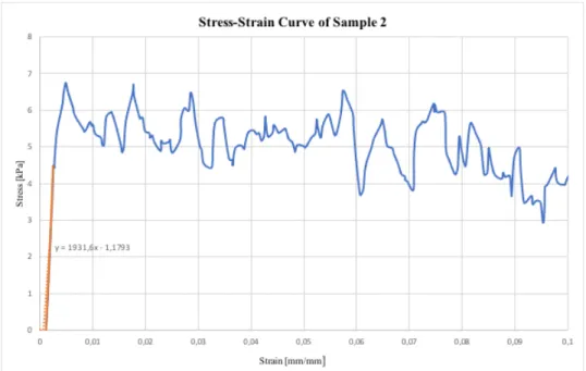
Per quanto riguarda le prove sperimentali, la Figura E mostra una delle curve sforzo deformazione ottenute a seguito di test eseguiti con la macchina da test TC3F. L’andamento è caratterizzato da una breve fase iniziale lineare seguita da una plastica più ampia. La linea arancione rappresenta il tratto considerato per il calcolo del modulo di Young.
XIII
Figura E Curva sforzo-deformazione di una campione con nervo ottico analizzato con la macchina TC3F. Sull’asse x le deformazioni sono espresse in [mm/mm] mentre sull’asse y gli sforzi sono espressi in [kPa].
Le Tabelle B e C riportano i valori medi dei parametri biomeccanici calcolati a seguito delle prove a trazione eseguite con la macchina da test TC3F rispettivamente su campioni con nervo ottico e senza.
Modulo di Young Medio [kPa] ± SD 1835 ± 1.35 Sforzo di Snervamento Medio [kPa] ± SD 3.03 ± 2.23 Sforzo a Rottura Medio [kPa] ± SD 7.46 ± 5.8 Deformazione a Rottura Media [mm/mm] ± SD 0.089 ± 0.1
Tabella B Valori medi dei parametri biomeccanici calcolati per campioni con nervo ottico e deviazione standard
Modulo di Young Medio [kPa] ± SD 3470 ± 3.09 Sforzo di snervamento medio [kPa] ± SD 9.15 ± 6.09 Sforzo a Rottura Medio [kPa] ± SD 9.76 ± 6.1 Deformazione a Rottura Media ± SD 0.113 ± 0.2
Tabella C Valori medi dei parametri biomeccanici calcolati per campioni senza nervo ottico e deviazione standard
XIV
Per entrambe le tipologie di prova, gli andamenti delle curve ottenute sono coerenti con quelli presenti in letteratura. Tuttavia, per entrambi i campioni, i valori di deformazione risultano essere molto bassi e questo influenza chiaramente i valori dei parametri biomeccanici: in particolare il modulo di Young risulta essere 1-2 ordini di grandezza maggiore rispetto allo stato dell’arte. Questo potrebbe essere dovuto al fatto che il software non acquisisce un numero di punti sufficiente a caratterizzare il tessuto in maniera soddisfacente.
È stato inoltre svolto un t-test con il fine di determinare se l’uso del nervo ottico come afferraggio potesse influenzare le proprietà meccaniche della retina e, in particolare, il valore del modulo di Young. I risultati dimostrano che i due protocolli portano a risultati privi di differenza significativa (P>0.05)
Infine, per quanto riguarda i test a trazione, la Figura F mostra una delle curve ottenute a seguito dei test effettuati sui campioni senza nervo ottico con la macchina EnduraTEC. Anche in questo caso la curva è caratterizzata da una breve fase elastica lineare seguita da una regione plastica più ampia.
Figura F Curva sforzo-deformazione di una campione senza nervo ottico analizzato con la macchina EnduraTEC. Sull’asse x le deformazioni sono espresse in [mm/mm] mentre sull’asse y gli sforzi sono
XV
La Tabella D riporta i parametri biomeccanici medi calcolati per questo tipo di prova.
Modulo di Young Medio [kPa] ± SD 13.4 ± 0.0067 Sforzo di Snervamento Medio [kPa] ± SD 1.33 ± 0.75
Sforzo a Rottura Medio [kPa] ± SD 2.21 ± 0.8 Deformazione a Rottura Media [mm/mm] ± SD 0.66 ± 0.3
Tabella D Valori medi dei parametri biomeccanici calcolati per campioni senza nervo ottico e deviazione standard
Le prove effettuate con la EnduraTEC non solo hanno restituito andamenti delle curve coerenti con quelli in letteratura, ma anche i valori dei parametri biomeccanici si sono rivelati essere in linea con quelli dei precedenti lavori.
Per quanto riguarda infine l’analisi DIC siamo in possesso di soli risultati preliminari e in particolare, si riporta di seguito la mappa colorimetrica delle deformazioni, in configurazione Euleriana, considerate nella direzione della forza applicata (Figura G). I valori di deformazione sono in linea con quelli derivanti dalle prove sperimentali svolte con l’EnduraTEC.
XVI
Conclusioni
Lo scopo principale di questo progetto di tesi è stato quello di eseguire una caratterizzazione biomeccanica della retina suina partendo da considerazioni fatte sul distacco di retina, una condizione patologica in cui la meccanica del tessuto è direttamente coinvolta. Conoscere le proprietà biomeccaniche di questo tessuto vorrebbe quindi dire avere la possibilità di migliorare le tecniche chirurgiche preesistenti o crearne di nuove.
In conclusione, possiamo dire che i parametri biomeccanici ottenuti a seguito delle analisi svolte sono coerenti con quelli presenti in letteratura che definiscono la retina un tessuto fragile con un comportamento biomeccanico caratterizzato da una breve fase elastica seguita da una fase plastica più ampia.
XVII
Abstract
Introduction
This thesis project aims to focus on the mechanical properties of the retina since, differently from other structures belonging to the visual system such as the sclera or the choroid, its biomechanical behavior has not been exhaustively studied, presumably due to the fragility of the tissue. This will was born from considerations regarding a very specific pathological state that can affect this membrane: the retinal detachment. In fact, this disease, compared to others, is characterized by a direct involvement of the mechanics of the tissue and, although it can be treated with various surgical techniques, it seems that none of them can ensure that no further intervention is required. Hence the importance of the study of the biomechanics of the retina: knowing its mechanical properties would mean having the opportunity to improve existing techniques, create new ones or otherwise generate computational models that can simulate the tissue, its pathology and its treatment.
To achieve this goal, it was decided to perform uniaxial tensile tests on retinal samples under different conditions. The testing process, in general, consists of placing the sample between two grips and slowly tensioning it until it breaks. Then, biomechanical parameters are calculated.
It is of fundamental importance, when dealing with biological tissues, to take into consideration some problems such as the non-homogeneity of the tissue and the inter-individual variability, the possibility that the tissue can be damaged during its retrieval, preparation and conservation. Other problems may be related to the imprecision in the measurement of the sample dimensions, fundamental for the calculation of the mechanical parameters and, finally, to the transfer of the sample between the two clamps. In the course of the discussion it will be possible to see how we tried to find a solution to most of these problems, which are consistent when we are talking about such a delicate sample as the retinal one.
XVIII
Materials and methods
In order to determine the biomechanical characteristics of the retina, tensile tests were carried out in different conditions. The experimental tests were performed on samples extracted from pig eyes supplied by Fumagalli Industria Alimentare Spa (Tavernerio, Como), and analyzed within about 10 hours of the animal's death at LaBS, Department of Chemistry, Materials and Chemical Engineering, Politecnico di Milan.
At first the tests were performed using a first test machine (TC3F, EBERS), consisting of a demountable test chamber with two grips inside: the upper mobile and the lower fixed. In this case, the tests were performed on two different types of sample: retina attached to the optic nerve (Fig.A-A), used as a grasp, and retina without an optic nerve, i.e. a single "sheet" of retina folded into 2 or 4 layers depending on the size initial of the specimen (Fig.A-B). In the second case, the tests were also carried out in the presence of phosphate-buffer-saline solution (PBS).
XIX
As regards the dimensions of the specimens, three were considered, essential for the calculation of the biomechanical parameters: L0, defined as the initial distance between the two clamps before the start of the test; the width, measured by a digital caliper after the sample is transferred between the grips, and the thickness. In this last case, the measurement was different for the two types of sample: in the case of the specimens attached to the optic nerve, the measurement was less precise with the advantage, however, of less difficulty in transferring the sample to the test chamber. In fact, what is obtained following the extraction protocol is an agglomeration of tissue in which it is impossible to determine in how many layers the retina has folded back on itself. For this reason, the thickness measurement was carried out roughly with a digital caliper as shown in Fig. B.
Fig. B Measurement of the thickness of a sample with optic nerve through a digital
In the case of samples without optic nerve, it was possible to estimate the thickness with greater precision. In fact, by folding the retina sample a known number of times and, knowing the initial thickness of a single layer, it was possible to obtain a more truthful measurement. As for the thickness of a single retinal layer, the value was estimated by Optical Coherence Tomography (OCT), a particularly important technique in ophthalmology that allows to obtain real-time images of the cross sections of the retina. This not only allows to evaluate any pathological states but also to obtain quantitative measures, as shown in Fig. C. The analysis was carried out on three pig eyes. Subsequently, through an image analysis carried out with ImageJ on the three tomographic images, it was possible to obtain an average thickness value that could be used for all samples without optic nerve
XX
Fig. C Tomographic image obtained from OCT analysis. The number in correspondence of the red line represents the retinal thickness in that point [µm]
9 tests were performed for both types of samples, applying a speed of 0.1 mm / s to the upper grip of the test machine.
Once the tests have been carried out, the software returns parameters including, in particular, the displacement [mm] and the force [N] applied to the sample. Starting from these, stresses [kPa] and strains [mm / mm] are calculated and then the stress-strain curve is plotted. From this the Young's modulus (E), defined as the angular coefficient of the linear part of the curve before the change of slope; the yield stress, the point at which there is a change in the trend of the curve; the stress at break; defined as the first stress value in which the curve clearly decreases and, finally, the deformation at break , that is the deformation value corresponding to the stress at break, are extracted
As regards the samples without optic nerve, at a later time, the tests were also carried out with a second machine (EnduraTEC, BOSE) (Fig.D), with the aim of comparing data resulting from two different protocols, although the methods of extraction of the samples, input parameters and output parameters remained the same. However, in this case, it was not possible to perform tests in the presence of PBS as the pre-existing test chamber was found to be unsuitable for transferring the retinal specimen between the grips. For this reason, one of the final steps of this thesis project involved the design of a new chamber that exceeded the limits of the first and, in particular, that would allow the sample to be mounted without damaging it. The tests were carried out on a total number of 16 retinal specimens and the calculated parameters were the same as the previously described tests.
XXI
Fig. D Tensile test machine EnduraTEC, BOSE
At the end of the tests, a statistical analysis was carried out on the calculated biomechanical parameters. In particular, the mean and standard deviation were calculated using Excel for each parameter taken into consideration. The values were then compared with those present in the literature. Moreover, between the two families of samples analyzed with the TC3F machine, a t-student test was carried out between the values of the Young's modulus in order to determine whether the use of optic nerve such as grasping could affect the mechanical properties of the retina.
Following some differences highlighted between the deformation values calculated at the end of the tensile tests performed with the TC3F and EnduraTEC machines, it was deemed appropriate to carry out a further analysis. Digital Image Correlation (DIC) is a non-invasive optical analysis that allows you to measure displacements and deformations on the surface of objects subject to stress. It is based on the monitoring of unique details present on the sample surface through numerical processing of digital images: by analyzing the gray values of different frames, the deformations and displacements can be quantified through a correlation algorithm. To apply the analysis to our samples it was necessary to create a pattern on their surface as uniform as possible and this was possible thanks to the use of toner powder on a toothbrush.
XXII
Results
The results deriving from each analysis carried out during this thesis project are reported below. For the mechanical tests, only the average values of the biomechanical parameters calculated following the various tests performed are reported.
Tab. A reports the final average value of the retinal thickness obtained after the image analysis performed on the tomographic images resulting from OCT.
It fits perfectly into the range of values found in the literature (300-400 µm) [19] and this makes OCT a valid and effective alternative measurement technique to those present in other works.
Final Average Value of Retinal Thickness[µm] Standard Deviation
351.75 38.45
Tab. A Final average value of retinal thickness and standard deviation
As for the experimental tests, Fig. E shows one of the stress-strain curves obtained following a tensile test performed with the TC3F test machine. The trend is characterized by a short linear initial phase followed by a larger plastic one. The orange line represents the section considered for the calculation of Young's modulus.
XXIII
Fig. E Stress-strain curve of a sample with optic nerve. On x-axis the strains are reported in [mm/mm] while on y-axis stresses are reported in [kPa]
Tab. B and C report the average values of the biomechanical parameters calculated following the tensile tests carried out with the first machine on samples with and without optic nerve respectively.
Average Young’s Modulus [kPa] ± SD 1835 ± 1.35 Average Yield Stress [kPa] ± SD 3.03 ± 2.23 Average Failure Stress [kPa] ± SD 7.46 ± 5.8 Average Failure Strain [mm/mm] ± SD 0.089 ± 0.1
Tab. B Average values of the biomechanical parameters calculated for samples with optic nerve and standard deviation
Average Young’s Modulus [kPa] ± SD 3470 ± 3.09 Average Yield Stress [kPa] ± SD 9.15 ± 6.09 Average Failure Stress [kPa] ± SD 9.76 ± 6.1 Average Failure Strain [mm/mm] ± SD 0.113 ± 0.2
Tab. C Average values of the biomechanical parameters calculated for sample without optic nerve and standard deviation
XXIV
For both types of tests, the trends of the curves obtained are consistent with those present in the literature. However, for both samples, the deformation values are very low, and this clearly affects the values of the others biomechanical parameters: in particular, Young's modulus is 1-2 orders of magnitude greater than the state of the art. This could be due to the fact that the software does not acquire a sufficient number of points to characterize the tissue satisfactorily.
A t-test was also carried out in order to determine if the use of the optic nerve as grasping could influence the mechanical properties of the retina and, in particular, the value of Young's modulus. The results demonstrate that the two protocols lead to results with no significant difference (P>0.05).
Finally, as regards the tensile tests, Fig. F shows one of the curves obtained following the tests carried out on samples without optic nerve with the EnduraTEC machine. Again, the curve is characterized by a short linear elastic phase followed by a wider plastic region.
Fig. F Stress-strain curve of a sample without optic nerve. On x-axis the strains are reported in [mm/mm] while on y-axis stresses are reported in [kPa]
XXV
Finally, Tab. D reports the average biomechanical parameters calculated for this type of test.
Average Young’s Modulus [kPa] ± SD 13.4 ± 0.0067 Average Yield Stress [kPa] ± SD 1.33 ± 0.75 Average Failure Stress [kPa] ± SD 2.21 ± 0.8 Average Failure Strain [mm/mm] ± SD 0.66 ± 0.3
Tab. D Average values of the biomechanical parameters calculated for sample without optic nerve and standard deviation
The tests carried out with the EnduraTEC not only returned curves consistent with those in the literature, but also the values of the biomechanical parameters proved to be in line with those of the previous works.
Finally, as regards the DIC analysis, we have only preliminary results and in particular, the following in Fig. G is the colorimetric map of the deformations, in Eulerian configuration, considered in the direction of the applied force. The deformation values are in line with those resulting from the experimental tests carried out with the EnduraTEC.
XXVI
Conclusions
The main purpose of this thesis project was to perform a biomechanical characterization of the porcine retina starting from considerations made on retinal detachment, a pathological condition in which the mechanics of the tissue is directly involved. Knowing the biomechanical properties of this tissue would therefore mean having the opportunity to improve pre-existing surgical techniques or create new ones.
In conclusion, we can say that the biomechanical parameters obtained following the analyzes carried out are consistent with those present in the literature which define the retina as a fragile tissue with a biomechanical behavior characterized by a short elastic phase followed by a larger plastic phase.
1
Chapter 1: Introduction
1.1 The Retina
The main organ of the visual system is the eye which is responsible for obtaining information from the surrounding environment through light, which is subsequently processed and sent to the brain where it is converted into an image. When the light beam reaches the eye, whose structure is schematized in Figure 1, the light intensity is regulated through a diaphragm, the iris. Then a system of lenses, the cornea and the crystalline, focuses the beam towards the retina which then converts the light information into electrical signals that will be sent to the brain through the optic nerve, processed and interpreted.
Figure 1 Eye Structure
The retina remains the most studied part of the human brain. It is considered embryologically as part of the central nervous system [1-3], but readily accessible to examination, it can be investigated with relative ease by both scientists and clinicians [14]. This work focuses precisely on the retina and, in particular, on its biomechanical characteristics. Infact, in contrast to other eye structures like sclera and choroid, the biomechanical behavior of the retina has not received much attention, presumably because of its structural fragility [26].
First of all, before dealing with retinal biomechanics, an overview of the retina from an anatomical, physiological and pathological point of view will be made in this paragraph.
2
1.1.1 Anatomy
The retina is the innermost membrane of the eyeball and represents the main component for vision thanks to the ability to convert the luminous radiation into electrical potential due to the presence of two types of photoreceptors: the cones and the rods. For this reason, it is considered the neurosensory component of the eye [14]. In particular, the retina forms the inner coating of the entire eyeball, from the starting point of the optic nerve to the pupillary margin of the iris, with a thickness varying between 0.4 and 0.1 mm respectively. Its outer part is supplied by a vascular layer, the choroid, and protect by a tough outer layer, the sclera [14].
The retina is divided into three portions: the optical part, applied to the choroid; the ciliary part, adherent to the ciliary body and the iris part. Among these, the only portion responsible for vision is the optical part due to the presence of the photoreceptors. The optical part can be divided into two sheets: the outer most is the layer of the pigmented cells, including photoreceptors and pigmented epithelial cells, while the inner one represents the nervous portion containing neuronal and glial cells.
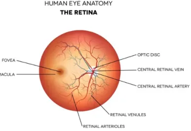
In addition, within the retina it is possible to distinguish three important physical elements, shown in Figure 2.
Figure 2 The three regions of the retina
The ora serrata is the line between the optical part and the ciliary part of the retina. It is located 6-7 mm behind the cornea and is the region in which the retina starts to change its structure thinning.
3
The optic disk (papilla ottica) is the point of convergence of the nerve fibers that will form the optic nerve and also the region from which retinal vessels emerge. It is a blind spot, being devoid of photoreceptors.
Finally, the macula is a region located in the posterior pole of the eye and crossed in the center by the visual axis of the eye. This central point of passage is called fovea, the area of best visual definition, in which the greatest number of light rays is concentrated, and which allows the most distinct and precise vision.
1.1.1.1 Retinal layers
The vertebrate retina, in the optical part, is divided into ten distinct layers in which the cellular elements are arranged and adapted to meet the functional requirements of the different regions of the retina [14].
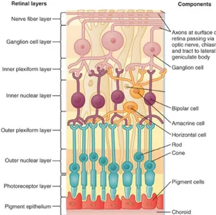
Figure 3 shows a schematic representation of the layers of the retina and the respective cells. The different layers are described below starting from the outermost, the closest to the choroid, towards the innermost, closest to the vitreous body.
4
The retinal pigment epithelium (RPE) is a single layer of cuboidal epithelial cells that adheres to the choroid and provides nourishment and supportive functions to the neurosensory retina. The pigmentation of these cells allows to absorb the light rays that are not converted by the photoreceptors to avoid the reflection of light. Moreover, it forms the blood-retina barrier which regulates the exchanges between blood and retinal tissues [6-11].
The photoreceptors layer is composed by the outer and inner segments of the photoreceptor cells. As mentioned before, there are two types of photoreceptors: the cones, responsible for color vision, and the rods, involved in monochromatic vision in low light conditions. In human retina we can find three different types of cones:
- S-cones with an absorption peak around 430 nm, sensitive to blue-violet color; - M-cones with an absorption peak around 530 nm, sensitive to green color; - L-cones with an absorption peak around 570 nm, sensitive to red range.
The photoreceptors are the sensors of the visual system that capture photons and convert them into a nerve signal in a process called phototransduction [16]. In particular, the human retina contains approximately 4-5 million cones and 77-107 million rods [12-14].
5
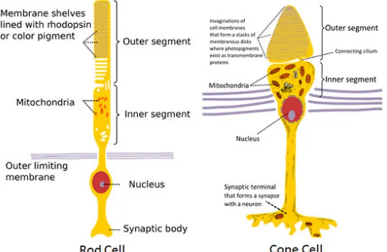
Each photoreceptor (Figure 4) consists of an outer segment (photopigment), inner segment (mitochondria, endoplasmic reticulum), a nucleus, an inner fiber (analogous to an axon) and a synaptic terminal [21]. The outer segments contain the photon-capturing photopigment [14]. So, in the outer segment, the light radiation causes a reversible chemical modification of the visual pigment and the creation of an electrical potential, which is transmitted to the bipolar cells and, subsequently, to the ganglionic one.
The external limiting membrane is a network-like structure which separates the inner segment portions of the photoreceptors from their cell nuclei.
The outer nuclear layer contains the cellular bodies of cones and rods.
The outer plexiform layer is the first synaptic zone. This layer is formed by projections of rods and cones ending in the rod spherule and cones pedicles, respectively. These establish synapses with dendrites of bipolar and horizontal cells [21].
The inner nuclear layer contains the nuclei and surrounding cell bodies of neurons such as amacrine cells, bipolar cells and horizontal cells.
The inner plexiform layer is the second retinal processing layer with networks between bipolar or amacrine cells and ganglion cells [14].
The ganglion cell layer contains nuclei of the ganglion neural cells, whose axons become the optic nerve fibers, and some displaced amacrine cells [21].
The nerve fiber layer contains the axons of the ganglion cell bodies.
Finally, the inner limiting membrane, is the basement membrane produced by Müller cells. Vitreous collagen fibrils insert into this membrane of the retina, so rendering the retina vulnerable to vitreoretinal traction forces [4].
6
1.1.1.2 Retinal vascularization
As said, the retina is stratified into different layers, each containing specific cell types or cellular compartments with different nutritional requirements [29].In order to satisfy these requirements, the ophthalmic artery bifurcates and supplies the retina through two distinct vascular networks: the retinal network and the choroidal network (choriocapillaris system).
Figure 5 Retinal main vessels
In the retinal network the central retinal artery, the red one in Figure 5, penetrates the eye through the papilla ottica and splits into four branches that diverge towards the periphery where they further divide. The blood containing waste products goes, through four veins branches, towards the papilla and flows out of the globe through the central vein of the retina. This network supplies nourishment to ganglion and bipolar cells and the layer of nerve fibers.
On the other hand, the retinal pigment epithelium layer and, through this, the photoreceptors are supplied by the choroidal network, which is composed by very large lumen and loose walls capillaries. For this reason, the filtration processes are abundant and poorly selective. The oxygenated blood flows through the posterior ciliary arteries, which form a kind of arterial ring around the head of the optic nerve, whereas the deoxygenated blood flows towards four or more vascular gaps (swirling veins).
7
1.1.2 Function
The retina is the structure of the eyeball used to capture the light stimuli that come from the outside and convert them into nerve signals that are sent, through the optic nerve, to the brain structures responsible for visual interpretation.
From a functional point of view the retinal layers can be reduced to three:
- Pigment epithelium and photoreceptors layer; - Bipolar, horizontal and amacrine cells layer; - Ganglion cells layer.
The starting point of the conversion process is performed by the photoreceptors: when the light radiation reaches the retina, photochemical reactions are activated. Indeed, when cones and rods are exposed to intense or weak light respectively, they are subject to conformational changes that cause the release of neurotransmitters which will excite, or inhibit, bipolar cells which, in turn, will send potentials to ganglion cells. The axonic extensions of the ganglion cells constitute the optic nerve which will have the task of conveying the signal out of the retina to the lateral geniculate body and the cortical areas of the brain, where visual information is processed.
Amacrine and horizontal cells modulate communication in the retinal nerve tissue.
1.1.3 Retinal detachment
The retina can be affected by various pathologies characterized, for example, by morphological and structural changes due to age or trauma. Among all retinal pathologies this research project intends to focus on retinal detachment, starting point of our considerations. The reason is to be found in the fact that retinal detachment is one of those pathological conditions in which the mechanics of the biological tissue is directly involved. Knowing the mechanical properties of the retina therefore means, in this case, having the
8
opportunity to implement pre-existing surgical techniques, create them ex novo or generate computational models that can simulate the pathology and its treatment.
This disease, mainly due to a trauma, concerns limited regions of retina, but generally tends to extend progressively and affect ever larger portions of the retina, thus causing the onset of a “dark area” that extends from the periphery towards the central portion of the visual field and leading to blindness [1]. As there is no drug therapy for retinal detachment, the gold standard procedure for treating retinal detachment is represented by urgent surgery.
1.1.3.1 Types, causes and diagnosis
Retinal detachment is a really serious disorder which occurs when the neural retina separates from the layer underneath, the RPE [11]. In this condition, retinal cells remain oxygen-free which can result in cell death and consequent total loss of vision. Symptoms include an increase in the number of floaters, flashes of light and worsening of the outer part of the visual field [10].
Retinal detachment can occur for various reasons among which the most common are:
- Posterior vitreous detachment: it represents the most common case and it is often related to the aging. Since the vitreous body is attached to the retina, its detachment can exert traction on the retina itself, causing it to detach from the RPE layer. - Severe myopia: people with sever myopia, greater than 5-6 diopters, present the
greatest risk of developing retinal detachment because they often have thinner retinas [13];
- Traumatic events: in some cases, the detachment of the retina is consequent to an injury to the face or eyeball associated, for example, with high-impact sport activities or at high speed;
- Cataract surgery: in some cases, retinal detachment is a serious complication of cataract surgery that can occur in the early or postoperative periods [13].
9
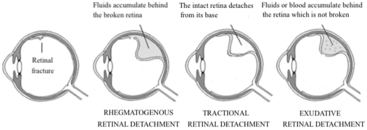
Depending on the pathogenesis, three types of retinal detachment can be distinguished. They are schematized in Figure 6 and described below.
Figure 6 Types of retinal detachment
In the rhegmatogenous retinal detachment the initial event consists in the contraction, due to different reasons, of the vitreous body, the transparent fluid that fills the space between the posterior surface of the crystallin lens and the walls of the retina, to which it adheres. This contraction could result in one or more retinal small fractures, due to the presence of pre-existing degenerative areas that make the retina fragile or thin, or lacerations, due to abnormal adhesions and tensile forces. In this way, the vitreous liquid is free to filter into the subretinal space causing the retina to lose adhesion with the pigmented epithelium.
A tractional retinal detachment occurs when fibrovascular tissue is formed as a result of trauma, inflammation or neovascularization. This fibrous matrix will pull the sensory retina from the retinal pigment epithelium.
Finally, an exudative retinal detachment occurs due to inflammation, injury or vascular abnormalities and results in fluid accumulating in the space below the retina without the presence of a hole or break.
Retinal detachment can be diagnosticated by ophthalmoscopy, a technique that uses an instrument that projects a beam of light through the pupil of the eye onto the retina. The
10
ophthalmoscope provides detailed information about the internal ocular structures and gives the doctor the possibility to see any retinal holes, lacerations or more serous detachments.
1.1.3.2 Treatments
Retinal detachment is treated like a medical emergency, as the risk of sight loss is high. If the intervention is immediate, the risk of permanently losing sight is greatly reduced. In most cases (85 %), only one surgery is needed to successfully reposition the retina and repair the lacerations present. Currently, about 95 % of cases of retinal detachment can be repaired successfully [28]. Unfortunately, after treatment, some patients do not fully recover their vision and may report permanent reduction of central or lateral vision, particularly if the macula was involved in the area of the detachment. Treatment failures usually involve either the failure to recognize all sites of detachment, the formation of new retinal breaks, or proliferative vitreoretinopathy [28].
There are several types of surgical approaches available to treat retinal detachment, including cryopexy and laser photocoagulation, scleral buckle surgery, vitrectomy and pneumatic retinopexy.
Cryopexy and laser photocoagulation are occasionally used alone to restore a small affected area so that the detachment does not spread. Cryosurgery is related to the use of extreme cold surgery in order to destroy abnormal or diseased tissues: its use for the treatment of retinal detachment generates a strong welding of the break margins. Laser photocoagulation works according to the same principle, the difference lies in the medium used which in this case in not a cold liquid or gas but a laser.
11
The scleral buckle surgery is a technique in which the surgeon places one or more silicone bands to the sclera, around the outside of the eye (Figure 7). This allows to the retina to settle again on the posterior wall of the eye: it provides a physical stimulus, pressure, to favor retinal reattachment. Typically, the buckle itself does not prevent a retinal break from opening again. Therefore, in addition to this procedure surgeon typically use laser photocoagulation. The risks for the surgery include infection, a raised pressure inside the eye, bleeding in the eye, detachment of the choroid layer and refractive error.
Figure 7 Eyeball before and after the placement of scleral buckle
Vitrectomy is the procedure used in the most complex cases. It consists in the removal of the vitreous gel thus ensuring the complete removal of the vitreous tractions that generated the retinal break. This is replaced by a gas bubble, air or silicone oil (Figure 8). The procedure ends with photocoagulation, to make sure that the retina permanently maintains the correct position.
12 The risks associated with vitrectomy are:
- High risk of proliferative vitreo-retinopathy (PVR) in case of failure. - Retinal detachment occurs again in 3-6% of cases.
When a study compared vitrectomy with scleral buckle surgery, it was found that although there may be less recurrence of detachment, vitrectomy may have little or no difference in success of operation and vision achivied [30]. Both vitrectomy and scleral buckle were associated with side effects: some adverse events appeared to be more common in the vitrectomy group, such as cataract progression and new iatrogenic breaks, whereas others were more commonly seen in the scleral buckling group such as choroidal detachment [30].
The pneumatic retinopexy is a technique that can be used if the detachment is mild and easy to repair. It consists in the injection into the eye of a small bubble of gas which will press against the retinal rupture and the surrounding area to seal it. The procedure is followed by photocoagulation to form a scar that helps the retina to fix to the inner wall of the eye. Pneumatic retinopexy has significantly lower success rates compared to scleral buckle surgery and vitrectomy. Initially successful cases have high probability of failing during the weeks and the months after surgery. A study compared outcomes from patients receiving reattachment from pneumatic retinopexy versus scleral buckle. It was found that eyes having received the pneumatic retinopexy procedure were more likely to have a recurrence of retinal detachment by follow-up, and were 11% less likely to achieve retinal reattachment, compared to scleral buckle [12].
The invasiveness of surgical operations and possible complications are the reasons why tissues mechanics is so interest in retina. In fact, this structure is very fragile and knowing its mechanical properties is essential to find a method that can increase the resistance of the retina to mechanical deformation during surgery.
13
1.2 Mechanical characterization of biological tissues
The study of the mechanical behavior of biological tissues is fundamental not only in the field of tissue and biomedical engineering but also as regards integration with information from sectors such as medicine and pharmaceutical research. Deepening understanding of Biomechanics is aimed at determining the constitutive link, i.e the model explaining the mechanical behavior of the tissue in vivo.
A mixed approach is often used to identify the constitutive link: it allows a partial knowledge of the physical laws that regulate the behavior of the tissue. This approach must follow some essential steps. First of all, an analysis of the composition and the structure of the tissue is required: this can be done with new observations or by referring to the information that can be found in literature. Depending on this first analysis, the context of the constitutive link is chosen, such as elasticity, viscoelasticity, poroelasticity, etc. The next step concerns the execution of experiments, motivated by the chosen field, on samples of biological tissue. Then the constitutive law is identified: it is a mathematical equation that describes the experimental behavior of the tissue. Finally, the last two steps concern the determination of the constitutive parameters, the coefficients of the constitutive law, and the validation of the model which takes place by comparing the results with the experimental data present in literature.
Dealing with biological soft tissues, it is necessary to take into consideration during the sample experiments some issues such as: non-homogeneity of the tissue and interindividual variability, alteration of the tissue structure during specimen collection, preparation and storage. Major problems also concern the imprecision in the relief of the dimensions of the samples, which are fundamental for the calculation of some parameters, and, finally, difficulties in preparing and grasping the samples. All these issues are true regarding retina tissue. In this work retinal mechanical properties during uniaxial tensile tests were analyzed.
14
1.2.1 Uniaxial tensile test
The uniaxial tensile test consists in applying a known axial tensile stress, force or elongation, to the test specimen, measuring its response in terms of axial elongation or stress. The test process involves placing the specimen between two grips, as shown in Figure 9, and slowly pulling it until fracture to establish how easily the sample deforms and breaks. In our case, a travel ramp has been applied to the upper grip with a speed equal to 0.1 mm/s which can be described by the relationship:
$ = !' ('
)' [++/-]
Where !' is the constant deformation imposed, )' is the time at which it is reached and (' is the initial length of the sample.
Figure 9 Scheme of a tensile test
Starting from the information obtained by the test, it is possible to calculate the main mechanical characteristics of the material thanks to De Saint Venant’s theory of solids. In particular, in this project, some parameters were of fundamental importance, and will be reported below.
15
The engineering strain ! can be calculate using the following relation:
! = ∆( − (' (' =
( − ('
(' [++/++]
Where ∆( is the change in the sample length, (' is the initial length and ( is the final length.
In the case of a time dependent tensile test the strain is calculated as:
!()) = (()3) − (()345)
(' [++/++]
Where (()3) is the length at the time i, (()345) is the length at the time i-1 and (' is the
initial length.
The force measurement is used to calculate the engineering stress 6:
6 = 7
8 [9:]
Where F is the tensile force and A is the nominal cross-section of the specimen. In the case of a time dependent tensile test the stress is calculated as:
6()) = 7()) − 78 '
' [9:]
Where 7' is the tensile force at time zero, 7()) is the tensile force at time t and 8' is the nominal cross-section of the specimen.
16
If stresses and strains are known for each moment of the test, it is possible to obtain a stress-strain curve which, in the case of viscoelastic materials, to which the retina belongs as found in literature, has the shape shown in Figure 10.
Figure 10 Example of stress-strain curve
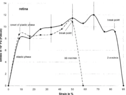
During every tensile test the viscoelastic sample passes through different phases which can be identified within the stress-strain diagram:
- The elastic field (0-Y) corresponds to the first phase of elastic linear deformation of the specimen. Deformations that occur in this phase are reversible and so, by removing the force there are no residual deformations of the sample but its initial length is restored.
- The end of the elastic field is determined by the yield point (6#): it determines a reduction in the strength of the material due to micro-cracks inside it. From this point the plastic field starts.
- In the plastic field (Y-B), the deformations are irreversible, which implies that, removing the load or the force, the sample shows residual deformations and therefore the deformations are no longer reversible.
- Once the maximum point of the graph has been reached, continuing the test leads to the breaking point (B). At this point corresponds the tensile failure stress (6;).
17
Knowing the stress and the strain it is also possible to calculate other characteristic properties of the material. In particular for our study a central role has been covered by the Young’s modulus (E) which can be calculated through Hook’s law as:
< = 6
! [9:]
E is a mechanical property that measures the stiffness of a solid material, the greater its value the greater the stiffness of the material. It defines the relationship between stress and strain in a material in the linear elasticity regime of a uniaxial deformation. In the stress-strain diagram corresponds to the angular coefficient of the linear section which represents the elastic field.
18
Chapter 2: State of the art
Only few studies have examined the mechanical properties of the retina [2]. In fact, since retina is so fragile as a biological material, its mechanical behavior has not received serious attention [26]. Although knowing mechanical properties is fundamental for many reasons, such as building reliable tissue engineered retina models.
This chapter aims at introducing the state of the art of the knowledge of retinal mechanical behavior through three previous studies, which will then be compared with the results deriving from this work.
In all the three works considered, as well as in the present, porcine retina was used in order to evaluate the mechanical properties of the retina. This is because, as it can be seen in Table 1, the pig eye is dimensionally and structurally similar to the human one compared to that of other species and is also easily available. The main difference between porcine and human retina is the absence of fovea and macula in the pig, however this is not relevant for mechanical properties. Figure 11 shows a schematic comparison between human and porcine retina.
The wording “tapetum”, in Table 1, refers to a reflective layer placed immediately behind the retina of some animals. Its task of reflecting light towards the retina increases the amount of light that can be captured by the retina itself and its absence is another common point between the human eye and the pig one.
Species Axial length [mm] Cornea thickness [mm] Macula Fovea Tapetum Retina thickness [mm] Human 23 0.5 Yes Yes No 0.1-0.4
Pig 24 1 No No No 0.3-0.4
19
Figure 11 Schematic representation of the human and the porcine retina. The sign "ONL" stays for Outer Nuclear Layer while the sign "OS" stays for Outer Segment
2.1 Biomechanical characteristics of retina
In 2004 Gregor Wollensak and Eberhard Spoerl, of the CGC University’s Department of Ophthalmology in Dresen, Germany, published a study whose aim was to examine the biomedical properties of porcine retina [25].
The samples were taken from enucleated porcine eyes within six hours postmortem and the average age of pigs was four months. The retina strips obtained had a length of 10 mm and a width of 7 mm and had been cutting paying attention to exclude the main vessels. The thickness was measured histologically and was found to be 0.252 ± 0.018 mm. After that, the specimens were transferred to a biomaterial test machine (MINIMAT, Rheometric Scientific GmbH) with a distance of 6 mm between the grips, as shown in Figure 12.
20
For stress-strain measurement 10 retina strips have been subjected to traction until failure with a velocity of 0.03 mm/s while 10 with a speed of 1.65 mm/s.
Figure 13 and Table 2 show the stress-strain curves corresponding to both test conditions and the main mechanical parameters measured respectively.
The study suggested that the biomechanical behavior of the retina is characterized by a short elastic phase and a remarkably broad plastic phase [25] which becomes shorter with a higher strain rate. However, the strain rate seemed not to affect the initial linear phase.
Figure 13 Stress-strain curves of retina with 0.03 mm/s and 1.65 mm/s (dashed lines) strain rate [25]. On x-axis the strain [%] while on y-x-axis the stress [103 Pa]
Parameters Retina 0.03 mm/s (n=10) Retina 1.65 mm/s (n=10) Young’s elastic modulus [kPa] 100 110
Stress at break point [kPa] 9.2 ± 1.4 11.3 ± 2.2 Yield stress [kPa] 8.0 ± 2.1 8.2 ± 1.4 Range of Plastic Phase Strain [mm/mm] 0.735 ± 0.022 0.422 ± 0.041
21
2.2 Dependence of the mechanical properties of the retina on
temperature
Chen and Weiland in 2012 studied the relationship between the mechanical properties of porcine retina samples and temperature during the tensile tests: equal amount of samples (n=5) were tested at body temperature (37.0 ± 0.3°C), room temperature (26.1 ± 0.1°C) and low temperature (7.8 ± 1.2°C) [3].
The 15 eyes they used were obtained within 3 hours postmortem and belonged to pigs aged between 3 and 7 months.
A retina flap of 1.5 mm in length and width and 0.3 ± 0.07 mm in thickness was taken from each eye: the sample was first immersed in a saline solution for 5 minutes and then remained in the saline when it was deformed by the tensile machine (Bose Electroforce 3100) with a displacement applied at 1mm/s [3]. The saline temperature was controlled through a heating system, part of the machine, and a chiller.
Figure 14 shows the stress-strain curves obtained in the three different test conditions while Table 3 lists the mechanical parameters of the tissue obtained by the study. In particular, they found out that the retina at 26.1 ± 0.1°C and 7.8 ± 1.2°C is significantly stiffer than the retina at 37.0 ± 0.3°C. Moreover, the retina at 7.8 ± 1.2°C is slightly stiffer than the retina at 26.1 ± 0.1°C, but the difference is not significant. As for the trends of the curves they seem to confirm the results obtained by Wollensak. In fact, also in this case, the curves are characterized by a linear elastic phase followed by a plastic region.
22
Figure 14 Stress-strain curves of the porcine retinal strips at (a) body temperature (37.0 ± 0.3°C), (b) room temperature (26.1 ± 0.1°C) and low temperature (7.8 ± 1.2°C) saline [3]. Stress is expressed in [kPa] while
![Fig. E Stress-strain curve of a sample with optic nerve. On x-axis the strains are reported in [mm/mm] while on y-axis stresses are reported in [kPa]](https://thumb-eu.123doks.com/thumbv2/123dokorg/7516160.105653/30.892.190.728.128.468/stress-strain-curve-sample-strains-reported-stresses-reported.webp)
![Fig. F Stress-strain curve of a sample without optic nerve. On x-axis the strains are reported in [mm/mm]](https://thumb-eu.123doks.com/thumbv2/123dokorg/7516160.105653/31.892.234.684.624.968/stress-strain-curve-sample-optic-nerve-strains-reported.webp)
![Figure 14 Stress-strain curves of the porcine retinal strips at (a) body temperature (37.0 ± 0.3°C), (b) room temperature (26.1 ± 0.1°C) and low temperature (7.8 ± 1.2°C) saline [3]](https://thumb-eu.123doks.com/thumbv2/123dokorg/7516160.105653/55.892.285.632.137.963/figure-stress-strain-porcine-retinal-temperature-temperature-temperature.webp)
![Figure 15 Stress-strain curves of strips containing superior-temporal vein (pink), superior-temporal artery (red) and no visible vessels (dark) [2]](https://thumb-eu.123doks.com/thumbv2/123dokorg/7516160.105653/57.892.317.600.138.362/figure-stress-containing-superior-temporal-superior-temporal-visible.webp)
